Optimizing Completion Time and Energy
Consumption in a Bidirectional Relay Network
(
Invited Paper
)
Huaping Liu
†,∗, Fan Sun
∗, Chan Dai Truyen Thai
∗, Elisabeth de Carvalho
∗and Petar Popovski
∗†
State Key Laboratory of Advanced Optical Communication Systems and Networks, Peking University, China
∗
Department of Electronic Systems, Aalborg University, Denmark
Email: [email protected],
{
fs,ttc,edc,petarp
}
@es.aau.dk
Abstract—Consider a wireless network with multiple sources and destinations, where the amount of data of each source node is finite. An interesting question is what is the shortest completion time, i. e. the time required that all data from the sources gets to the respective destinations. A similar question arises for the minimal required energy. While the requirement for minimal energy consumption is obvious, the shortest completion time is relevant when certain multi-node network needs to reserve the wireless medium in order to carry out the data exchange among its nodes. The completion time/energy consumption required for multiple flows depends on the current channel realizations, trans-mission methods used and, notably, the relation between the data sizes of different source nodes. In this paper we investigate the shortest completion time and minimal energy consumption in a two-way relay wireless network. The system applies optimal time multiplexing of several known transmission methods, including one-way relaying and wireless network coding (WNC). We show that when the relay applies Amplify-and-Forward (AF), both minimizations are linear optimization problems. On the other hand, when the relay uses Decode-and-Forward (DF), each of them is a quadratic optimization problem. The results show that, for given channel realizations, there is an optimal ratio of the data packets at the sources to obtain minimal completion time or energy consumption. This can be used as a guidance for the nodes to applytraffic shaping. In most cases, DF leads to shorter completion time and energy consumption compared to AF.
I. INTRODUCTION
In many wireless networks, notably WiFi, wireless medium is used through an exclusive reservation by a single node at a given time. The reservation time used depends on the current channel conditions and the amount of data that the node has to send. Nevertheless, the recent concepts of wireless network coding [1] or interference alignment [2] dictate that multiple communication flows should be served simultaneously over the shared wireless medium. Interference is not avoided, but it is contained and processed as a part of the transmission. Yet, although it is in theory optimal to allow all flows in the network to be served simultaneously, synchronization and coordination imply that it is practical to serve only a small, limited amount of flows at a given time. On the other hand, different groups of flows use the wireless medium in a time-division manner. Then the following question is of interest: given the channel conditions and the data size that each flow needs to transfer, what is the minimal completion time until all the data reaches their destinations? A related question is
what is theminimal energyneeded to transfer the data. An interesting parameter that has an impact is the relation between the data sizes of different source nodes. In the case where some users have deterministic application-wise packet lengths while the other users with a lower priority have adjustable packet lengths, the problem is solved by first satisfying the conditions according to the users with a higher priority. The lengths of the packets of the other users will be then optimized to have the shortest completion time and selected accordingly. We term this problemtraffic shaping.
Prior works have treated the completion time region and the weighted sum completion time for multiple access (MA) channel [3], broadcast (BC) channel and interference channel [4] [5]. In this paper, we investigate the minimal completion time and energy consumption in a scenario with bidirectional relaying. In the recent years, two-way relaying has been tightly associated with the technique of wireless network coding (WNC). On the other hand, other transmission modes can support two-way communication, such as time-division of the direct link between two end nodes. In order to calculate the minimal completion time, we consider several known trans-mission schemes as building blocks, used in a time-division manner. For example, consider the two-way communication between the nodes U1 and U2 aided by a relay station (RS) that operates by using Amplify-and-Forward (AF). Assume that there is much more data to send from U1 to U2 compared to the data size flowing in the opposite direction; then, in addition to the WNC based on AF, the completion time may include direct transmission from U1 to U2. We formulate two different optimization problems, when the relay works in an AF and Decode-and-Forward (DF) mode, respectively. Since for each assumed mode of the relay there are several possible blocks, we analyze how to eliminate some of the blocks from consideration under given channel conditions. The results show that, for given channel conditions, the minimal completion time and energy consumption significantly depend on the ratio between the data sizes at the two source nodes.
II. SYSTEMMODEL
not necessarily equal, but are assumed to be sufficiently large, in order to ensure that the communication rates be approx-imated by the information-theoretic rates. Our performance measures are the completion time and energy consumption normalized by the total data size b1+b2. This normalization
allows us to define the performance through the ratiob1/b2and
not the individual values b1, b2. The normalized completion
time and energy consumption serves as lower bounds for the case of finite packet sizes.
All the nodes are half-duplex, such that a node can either transmit or receive at a given time. The channels are denoted byh0(U1-U2),h1(U1-RS) andh2(U2-RS).h0is the channel
of the direct link, h1 and h2 are the channels from U1 and
U2 to the relay. Each channel hl, l∈ {0,1,2}, is reciprocal, known at all the nodes. We assume that the transmitted power is the same at all nodes, i.e. E{|xi|2} = P, where xi is the signal transmitted from node i∈ {U1,U2,RS}. Regarding the energy consumption, we only consider the contribution from the transmitted power, neglecting the power required to run the receivers. The noise zj at each node has a zero-mean complex circularly symmetric Gaussian distribution:
zj ∼ CN(0, σ2), j∈ {U1,U2,RS}. We defineγl= P|hl|2
σ2 , l∈
{0,1,2}, whereγl is the SNR of linkl. Then the capacity of a single link is C(γ) = log2(1 +γ).
U1 U2
RS
U1 U2
RS RS
U1 U2
RS
U1 U2
RS RS
U2 U1 U1 U2 U1 U2
(1) (2) (3) (4)
(5) (6) (7) (8)
Figure 1. Available transmission schemes used as basic blocks (BBs).
Each Ui has data traffic for the other user. These two traffic flows can be served using different transmission schemes, involving the combination of different flows in a variable number of transmission periods. We define 8 basic blocks (BB), represented by the transmission schemes on Fig. 1. The set of BBs is restricted to the ones where the terminals receive signals either from the other terminal or from the relay, but not simultaneously through the multiple access channel. On the other hand, the relay can receive signals from the terminals through a multiple access channel.
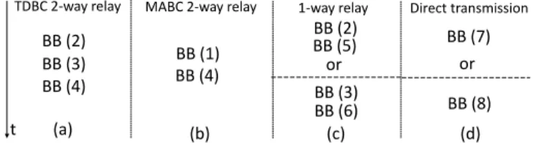
A given transmission scheme can be described as a con-catenation of BBs. The time sequence of BBs needs to satisfy certain constraints. For example, the BBs with uplink transmission should be selected before the BBs with downlink transmission. The task of appropriately ordering the BBs can be alleviated by defining a set of composite blocks (CBs) which groups the valid combinations of the BBs. The set of CBs is described in Fig. 2. The two-way relaying with Time Division Broadcast (TDBC) on Fig. 2(a) is a CB consisting of three BBs (and three transmission phases), while the two-way relaying with Multiple Access Broadcast (MABC) on Fig. 2(b) consists of two BBs. Both CBs, with TDBC and MABC,
involve WNC at the relay. The other two CBs, depicted on Fig. 2(c) and Fig. 2(d), involve unidirectional forwarding by the relay and two-way direct communication, respectively.
The objective is to find the combination and durations of CBs that optimize the completion time or energy consumption. The optimization procedure is different, depending on whether AF or DF is used at the relay. For DF, because the signals are decoded at the relay, the dependency between BBs inside a CB is removed and the optimization can be conducted for each BB independently. As AF relays the signal untouched, the BBs remain interdependent and the optimization has to be conducted jointly over all the CBs.
TDBC 2-way relay MABC 2-way relay 1-way relay Direct transmission
or
(a) (b) (c) (d)
BB (2) BB (3) BB (4)
BB (1)
t
BB (4)
BB (2) BB (5)
BB (3) BB (6)
or BB (7)
BB (8)
Figure 2. Composite blocks (CBs)
III. OPTIMIZATION FORAFRELAYING
In this section, we formulate the two optimization problems for AF relaying under the packet size constraint sent from both users.
A. Maximal achievable rates
In AF, all phase durations are equal, since relaying is performed on a symbol by symbol basis. Therefore, each phase in TDBC requires one third of the total duration of the CB. Each phase in MABC and one-way relay CB requires one half of the duration of the corresponding CB. From [6], the achievable rates for the TDBC are
RaUi =
1 3C
γ0+
γiγj γi+ 3γj+ 2
, (i, j)∈ {(1,2),(2,1)}.
(1) From [6], the achievable rates for MABC are
RbUi= 1 2C
γ
iγj γi+ 2γj+ 1
, (i, j)∈ {(1,2),(2,1)}. (2) From [7], the achievable rates for the unidirectional one-way relay areRc
U1=R
c
U2= 1 2C
γ0+γ1γ+1γγ22+1
. At last, the achievable rates of the unidirectional direct transmission are
Rd
U1 = R
d
U2 = C(γ0). The optimization formulation can be
simplified by keeping only one of the two unidirectional CBs for a given transmission direction:
R∗U1=R∗U2= max
1
2C
γ0+
γ1γ2 γ1+γ2+ 1
, C(γ0)
.
(3)
B. Formulation of the optimization problem for AF
1) Completion time: The transmission scheme is now made
out of 4 CBs: (1) TDBC which has a duration denoted asta, (2) MABC which has a duration denoted as tb, (3) unidirec-tional CB with transmission from U1 with durationt1
∗and (4)
unidirectional CB with transmission from U2 with durationt2 ∗.
2) Energy consumption: For MABC, the total transmission power is equal to 2P during the multiple access (MA) phase and equal to P during the broadcast (BC) phase. When the relay applies AF, the durations of the MA phase and BC phase are equal, so the MABC has an average power of 1.5P. The other CBs have an average power ofP. Then the whole energy consumption is E= 1.5P tb+P ta+t1∗+t2∗
.
3) Constraint: The transmission scheme made from the
combination of the 4 CBs has to transmit bi bits from Ui, which is expressed as the following constraint:
bi=taRUia +tbRbUi+t
i
∗R∗Ui, i= 1,2. (4)
4) Optimization criterion: For a given SNR setup and
values of b1 and b2, we can formulate the completion time
and energy consumption optimization problem as a linear optimization problem as follows:
min
ta,tb,t1∗,t2∗≥0
T or E
s.t. b1=taRU1a +tbRbU1+t 1 ∗R∗U1 b2=taRaU2+tbRU2b +t
2 ∗R∗U2.
(5)
IV. THE CASE OFDFRELAYING
In the AF case, there are only 4 variables to optimize, i.e.
ta, tb, t1∗, t2∗. The number of variables is small because each
phase of AF relaying has the same duration. In DF relaying, the duration of each phase can be different in a specific CB which means that the BBs have a different duration which should be optimized. The 4 CBs in Fig. 2 have 11 BBs which correspond to 11 variables. And for MABC, the MA rates of two links need also to be optimized leading 2 additional variables. Therefore, the optimization problem for DF contains 13 independent variables.
We simplify the optimization problem for DF in 2 steps. The first step is to decrease the number of optional CBs in Fig. 2. In the second step, we exploit the fact that the BBs within a same CB can be optimized separately: this leads to an optimization based on BBs and not CBs. Furthermore, the BBs that are common to multiple CBs have the same performance and hence can be described using a single optimization variable. This indicates that, the optimization for DF based on BBs relies on less variables than the optimization based on CBs.
In order to reduce the number of considered CBs, we rely on the following proposition:
Proposition 1: There are two different regions depending
on the relations between the SNRs:
• Case 1: If γ0 ≥min{γ1, γ2}, then it is optimal to use
only direct transmission.
• Case 2: If γ0 < min{γ1, γ2}, then it is optimal not to
use the direct transmission, but only the other three CBs. The proof is provided in Appendix A.
Proposition 2: If DF relaying is used, then if two or more
CBs use the same BB, then it is sufficient to have only one optimization variable corresponding to that BB.
The proof is deferred to Appendix B. This proposition implies that the optimization problem can be reformulated into a new
optimization problem that uses only six BBs (1)-(6) from Fig. 1.
To summarize, distinguishing between 2 SNR cases allows a decrease in the CB options available, eliminating the use of at least two variables. Removing common BBs between CBs eliminates the use of at least three variables. We can cut down at least five variables, then there are at most eight variables to optimize.
V. OPTIMIZATION PROBLEM FORDFRELAYING
Based on section IV, the optimization problem formu-lation will be discussed under 2 conditions, one is γ0 ≥
min{γ1, γ2}, another isγ0<min{γ1, γ2}.
A. Direct link stronger than at least one of the relay links
Whenγ0 ≥min{γ1, γ2}, only the direct transmission CB
is chosen. Then T =b1+b2
C(γ0) andE=
P(b1+b2)
C(γ0) .
B. Direct link weaker than the relay links
1) Objective functions: When γ0 <min{γ1, γ2}, TDBC,
MABC and one-way relay CBs are the available options and the optimal transmission scheme is built from the BBs (1), (2), (3), (4), (5) and (6) in Fig. 1, each having a durationt(1),t(2), t(3),t(4),t(5) andt(6) respectively. Then the total completion
time and energy consumption are
T =t(1)+t(2)+t(3)+t(4)+t(5)+t(6) (6a) E= 2P t(1)+P t(2)+t(3)+t(4)+t(5)+t(6)
. (6b)
2) Constraints: The time completion and energy
consump-tion are optimized under 2 sets of constraints that are derived below. The first set of constraints reflects the fact that, for an optimal operation, the number of bits transmitted to the relay should be equal to the number of bits that the relay transmits. The second set states that the number of bits transmitted by U1 and U2 should be equal to b1 andb2 respectively.
a) First set of constraints: We distinguish between 2
types of data: the data that is carried though the relay and the data that is sent through a direct link. The first type includes BBs (1),(4),(5),(6) and only the link to the relay in BBs (2),(3). The second type includes the direct link in BBs (2),(3).
Furthermore, in the first type of traffic, we distinguish between the BBs involving uplink transmissions, i.e. BBs (1)-(3), and the BBs involving downlink transmissions, i.e. BBs (4)-(6). We compute the number of bits sent in the uplink.
• BB (1). We denoteRmaci as the maximal achievable rate for the transmission from Ui to Uj (j6=i) (MA channel). Note thatRmac
i should satisfy the MA channel constraints in (9). The number of bits received at the RS intended to U1 is equal tot(1)Rmac2 . Likewise, the number of bits
received at the RS intended to U2 to equal to t(1)R1mac. • BB (2),(3). The number of bits received from U2 is t(3)C(γ2). However, the relay only forwards a part of the
Likewise, the number of bits that is forwarded by the relay to U2 is t(2)(C(γ1)−C(γ0)).
Denoting Qu1 and Qu2 as the total number of bits to be
forwarded at the RS to U1 and U2 resp., we have:
Qu1 =t(1)Rmac2 +t(3)[C(γ2)−C(γ0)] (7a) Qu2 =t(1)Rmac1 +t(2)[C(γ1)−C(γ0)]. (7b)
The number of bits sent in the downlink from the relay is
• BB (4). From [8], the maximal achievable rate for each
link isC(γ1)andC(γ2), i.e. the maximal achievable rate
for each individual link. Hence, the number of bits sent to U1 is t(4)C(γ1)while the number of bits sent to U2
is t(4)C(γ2).
• BB (5)-(6). The number of bits sent to U1 is t(6)C(γ1),
while the number of bits sent to U2 is t(5)C(γ2).
Denoting Qd
1 and Qd2 as the total number of bits to be sent
from the RS to U1 and U2 resp., we have:
Qd1= t(4)+t(6)
C(γ1), Qd2= t(4)+t(5)
C(γ2). (8)
Because the amount of uplink data should be equal to the amount of downlink data for each user, we get the first set of constraints: Qd
1 =Qu1 =Q1 andQd2=Qu2 =Q2.
b) Second set of constraints: This set of constraints state
that the total number of bits transmitted to Ui should be equal to bi. Considering Qd1 = Qu1 = Q1, b1 = Q2+t(2)C(γ0)
wheret(2)C(γ0)is the number of bits transmitted through the
direct link in BB (2). Likewise, b2 =Q1+t(3)C(γ0), where t(2)C(γ0)is the number of bits transmitted through the direct
link in BB (3). Using equation (7), we get the following set of constraints: b1=t(1)Rmac1 +t(2)C(γ1), b2 =t(1)Rmac2 + t(3)C(γ2).
3) Optimization Criterion:
min
t(i)≥0
T or E
s.t. Rmac1 +Rmac2 ≤C(γ1+γ2)
Rmac1 ≤C(γ1), Rmac2 ≤C(γ2) (9)
b1=t(1)Rmac1 +t(2)C(γ1), b2=t(1)R2mac+t(3)C(γ2) t(4)+t(6)
C(γ1) =t(1)Rmac2 +t(3)[C(γ2)−C(γ0)] t(4)+t(5)
C(γ2) =t(1)Rmac1 +t(2)[C(γ1)−C(γ0)].
This is a quadratic optimization problem [9]. VI. NUMERICAL RESULTS
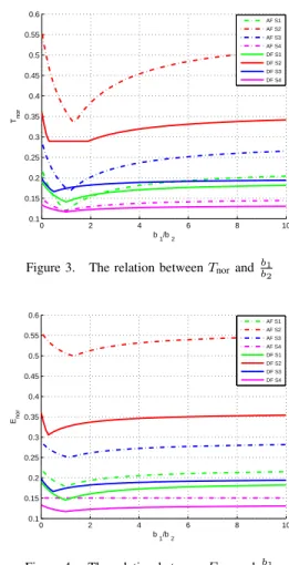
We define the normalized completion time and energy con-sumption as: Tnor = T/(b1+b2)andEnor=E/P(b1+b2). Tnor and Enor depend on the ratio between packet sizes b1/b2, and not the individual packet sizes. We present the
relation between Tnor, Enor and bb12 in Fig. 3 and Fig. 4.
S1 stands for γ0 = 0dB, γ1 = 30dB, γ2 = 30dB. S2
is with γ0 = 0dB, γ1 = 30dB, γ2 = 10dB. S3 stands
for γ0 = 10dB, γ1 = 30dB, γ2 = 20dB. S4 represents γ0 = 20dB, γ1 = 30dB, γ2 = 30dB. Here, we only draw
the case when γ0 < min{γ1, γ2}. If γ0 ≥ min{γ1, γ2},
the AF and DF both degrade to direct transmission (when
γ0≥min{γ1, γ2,0dB}, the direct transmission CB is the best
choice for AF), the corresponding comparison is not included. In most cases the completion time of DF is shorter than AF, but AF can achieve a shorter completion time than DF for some values ofb1/b2. Then if we adaptively communicate
between AF and DF, the completion time is the lowest envelop of the completion time curves of AF and DF. These results can help the users do spectrum reservation and traffic shaping as mentioned in the introduction part. However, the DF always has smaller energy consumption than AF as Fig. 4 shows.
0 2 4 6 8 10
0.1 0.15 0.2 0.25 0.3 0.35 0.4 0.45 0.5 0.55 0.6
b 1/b 2
Tnor
AF S1 AF S2 AF S3 AF S4 DF S1 DF S2 DF S3 DF S4
Figure 3. The relation betweenTnorand bb1
2
0 2 4 6 8 10
0.1 0.15 0.2 0.25 0.3 0.35 0.4 0.45 0.5 0.55 0.6
b
1/b 2 Enor
AF S1 AF S2 AF S3 AF S4 DF S1 DF S2 DF S3 DF S4
Figure 4. The relation betweenEnorand bb1
2
VII. CONCLUSION
ACKNOWLEDGMENT
This work is supported by the Danish Research Council for Technology and Production, grant nr. 065035 and 09-065920. And it is also supported by China Scholarship Council and Chinese 863 HighTech Project 2011AA01A106.
APPENDIXA PROOF OFPROPOSITION1
We conduct the proof by comparing the direct transmission CB with the one-way relay, the MABC two-way relay and the TDBC two-way relay CBs, respectively.
We first look at the relation between one-way relaying and direct transmission. Let U1 be the source node. If the first phase of one-way relay requires time τ1, the source node
will transmitτ1max{C(γ0), C(γ1)} bits. τ1C(γ0)bits will
be decoded by the destination node at the end of phase 1. When γ0 ≥ γ1, obviously the total information should be
sent through the direct link. When γ1 > γ0, the optimal
transmission strategy is as follows: Because the relay node knows the SNR of the direct link, the relay node knows that τ1C(γ0) bits have been successfully decoded by the
destination node. Then the relay node only forwards the re-maining informationτ1[C(γ1)−C(γ0)]in the second phase.
Assume the second phase duration of one-way relay isτ2, then τ1[C(γ1)−C(γ0)] = τ2C(γ2). The achievable rate of U1
can be obtained
ˆ
RcU1=τ1C(γ1)
τ1+τ2
= C(γ1)C(γ2)
C(γ1) +C(γ2)−C(γ0)
(10)
which is the lower bound in [10]. From (10), when γ1 > γ0> γ2, we haveRˆcU1< C(γ0), and one-way relay will not
be chosen. When γ0<min{γ1, γ2}, we have RˆcU1> C(γ0)
and direct transmission will not be chosen.
In order to see the relation between MABC and a direct transmission, define Ri as the rate of Ui, tu and td as the uplink duration and downlink duration, respectively. The following inequalities hold:
R1≤min{tu/(tu+td)C(γ1), td/(tu+td)C(γ2)} (11a) R2≤min{tu/(tu+td)C(γ2), td/(tu+td)C(γ1)}. (11b)
ThenR1+R2≤min{C(γ1), C(γ2)}is satisfied. Therefore, if γ0>min{γ1, γ2}, we haveR1+R2< C(γ0). There exists a
time sharing variableτ∈[0,1]to ensureR1< τ C(γ0), R2<
(1−τ)C(γ0). Then a direct transmission from U1 with time
sharingτ followed by a direct transmission from U2 with time sharing 1−τ outperforms MABC.
Using an similar analysis, it can be shown that if γ0 ≥
min{γ1, γ2}, TDBC is worse compared to direct transmission.
In summary, if γ0 ≥min{γ1, γ2}, the direct transmission
CB is the optimal choice. If γ0 <min{γ1, γ2}, direct
trans-mission is worse than one-way relay, then direct transtrans-mission will not be selected.
APPENDIXB PROOF OFPROPOSITION2
We observe that the CBs have BBs in common (see Fig. 2). We prove that the common BBs have the same performance when using DF relaying whatever the CB they are incorporated in. This means that we can convert the CB optimization problem to an optimization problem based on BBs. Whenγ0≥
min{γ1, γ2}, only the direct transmission CB is selected and
there is no common building blocks. Whenγ0<min{γ1, γ2},
there are 3 available relay CBs: TDBC, MABC and one-way relay. The common BBs are (2), (3) and (4).
The destination node of DF decodes the information from the direct link and the relay links separately. Part of the information is sent through the direct link while the rest of the information is sent from the relay. This means that the signals sent through the links i.e. RS→U2 and U1→U2 are independent. Then BBs (2) and (3) are independent from BBs (4), (5) and (6) (this condition cannot be met in AF). Based on the above result, the common BBs (2) and (3) in TDBC and one-way relay have the same performance. Therefore, a single optimization variable can be used to account for the same BB. BB (4) is another common block. It has the same function in both TDBC and MABC to transmit the information from the relay node to U1 and U2. TDBC and MABC both satisfy the condition of side information. Therefore, the rate of each link in BB (4) can achieve the capacity from [8] and BB (4) has the same performance in TDBC and MABC.
REFERENCES
[1] P. Popovski and H. Yomo, “Physical network coding in two-way wireless relay channels,” inCommunications, 2007. ICC ’07. IEEE International Conference on, june 2007, pp. 707 –712.
[2] V. Cadambe and S. Jafar, “Interference alignment and degrees of freedom of the -user interference channel,”Information Theory, IEEE Transactions on, vol. 54, no. 8, pp. 3425 –3441, aug. 2008.
[3] Y. Liu and E. Erkip, “Completion time in multi-access channel: An information theoretic perspective,” in Information Theory Workshop (ITW), 2011 IEEE, oct. 2011, pp. 708 –712.
[4] ——, “Completion time in broadcast channel and interference channel,” inCommunication, Control, and Computing (Allerton), 2011 49th An-nual Allerton Conference on, sept. 2011, pp. 1694 –1701.
[5] C. Ng, M. Medard, and A. Ozdaglar, “Completion time minimization and robust power control in wireless packet networks,” inCommunications, 2009. ICC ’09. IEEE International Conference on, june 2009, pp. 1 –6. [6] S. J. Kim, N. Devroye, P. Mitran, and V. Tarokh, “Achievable rate regions and performance comparison of half duplex bi-directional relaying protocols,”Information Theory, IEEE Transactions on, vol. 57, no. 10, pp. 6405 –6418, oct. 2011.
[7] J. Laneman, D. Tse, and G. Wornell, “Cooperative diversity in wireless networks: Efficient protocols and outage behavior,”Information Theory, IEEE Transactions on, vol. 50, no. 12, pp. 3062 – 3080, dec. 2004. [8] T. Oechtering, C. Schnurr, I. Bjelakovic, and H. Boche, “Broadcast
capacity region of two-phase bidirectional relaying,”Information Theory, IEEE Transactions on, vol. 54, no. 1, pp. 454 –458, jan. 2008. [9] S. Boyd and L. Vandenberghe, Convex Optimization. Cambridge
University Press, Mar. 2004.