Model Block Press Design
Final Design Review
December 5, 2019
for CVBT Thailand
The Blockheads –
[email protected]
Alexander Giannousis -
[email protected]
Ben van Hamersveld -
[email protected]
Chester Wong –
[email protected]
College of Engineering
California Polytechnic State University, San Luis Obispo
Table of Contents
Abstract 1
1.0 Introduction 1
2.0 Background 1
2.1 Interviews 1
2.2 Existing Designs 1
3.0 Objectives 4
3.1 Problem Statement 4
3.2 Boundary Sketch 5
3.3 Customer Wants and Needs 5
3.4 Quality Function Deployment (QFD) 5
3.5 Engineering Specifications 6
4.0 Concept Design 7
4.1 Considered Designs 7
4.2 Design Selection 13
5.0 Final Design 14
5.1 Functionality 15
6.0 Manufacturing Plan 16
6.1 Procurement 16
6.2 Manufacturing 16
6.3 Assembly 18
6.4 Safety 24
6.5 Maintenance 24
6.6 Repair 24
7.0 Design Verification 24
7.1 Test Results 24
7.2 Design Changes 25
8.0 Project Management 25
8.1 Timeline 26
9.0 Conclusion 26
9.1 Next Steps 26
Works Cited 27
Appendix 1. QFD House of Quality Table 28
Appendix 3. Preliminary Force Calculations 30
Appendix 4. Operation Manual 31
Appendix 5. Design Hazard Checklist 35
Appendix 6. Indented Bill of Materials with Cost Analysis 37
Appendix 7. FMEA 38
Appendix 8. DVP&R 39
Appendix 9. Test Plan 40
List of Figures
Figure 1. CINVA RAM Block Press 2
Figure 2. CETA Ram Block Press 2
Figure 3. Astram Soil Block Machine 3
Figure 4. CVBT BP9 3
Figure 5. CVBT BP6 3
Figure 6. CVBT BP10 4
Figure 7. Boundary Sketch 5
Figure 8. Traditional Press and Lever and Pivot Extraction Methods (CVBT BP10) 7 Figure 9. Hand Press and Removable Base Design 8
Figure 10. Astram Block Press Design 9
Figure 11. Floor Pump Crank Press (FPCP) 10
Figure 12. FPCP Internal Components 11
Figure 13. Eccentric Crank Shaft Press and Big Eccentric Extraction Methods 12
Figure 14. Cam Crank Press 13
Figure 15. Cam Crank External Components 15 Figure 16. Cam Crank Internal Components 15 Figure 17. Side and End Walls Placed Against Wood Block 18 Figure 18. Dimetric Cam Subassembly Setup for Welding 19 Figure 19. Dimetric Assembly of Cam Shaft and Body 20 Figure 20. Dimetric Assembly of Baseplate and Body 21 Figure 21. Dimetric Assembly of Latch Hooks and Body 22 Figure 22. Front View Assembly of Baseplate Guides and Body 22 Figure 23. Dimetric Assembly of Lid and Body 23 Figure 24. Dimetric Full Assembly with Baseplate Extrusion Guides (Highlighted) 23
List of Tables
Table 1. Engineering Specifications Table 6 Table 2. Pugh Matrix for Compression Technique 14 Table 3. Pugh Matrix for Extraction Technique 14
Abstract
This project’s goal is to redesign the Center for Vocational Building Technology (CVBT) BP9 earth block press, which makes 1/3 scale compressed earth blocks to build demonstration model homes in Thailand. The full-scale block press, the BP6, provides a sustainable and affordable technique for constructing habitable homes in Thailand. The BP9 serves as a tool to inform the public of the advantages of human-powered earth block presses through demonstration. The BP9 press design has multiple problems: it is too expensive to manufacture, there is too much friction when used, it has several weak points due to users unintentionally applying excessive force, and it cannot make channel or half blocks. Some experienced block press users were interviewed to gather opinions on what improvements and/or changes should be implemented in the new block press design. The main takeaway was that the press’s structural supports should be reinforced or redesigned. This document also includes some other existing full-scale press designs. The main objectives for this project are to eliminate the weak points and to reduce the cost. A full redesign with an entirely different mechanism was decided upon, and this process is detailed in the document, as well as the details of the design itself. The manufacturing and design verification plan, as well as the timeline of this project, are also detailed in the document.
1.0 Introduction
CVBT is an organization in Thailand that promotes local production of construction materials. One of these materials is a compressed earth block, which is produced using a block press. In addition to full scale presses, they also have a 1/3 scale model, called the BP9. This press currently has issues that CVBT would like to improve upon. The Blockheads, which consist of three mechanical engineering students from Cal Poly San Luis Obispo, have been asked to mitigate or eliminate these issues. This Final Design Review will include everything from the Critical Design Review (provide relevant research, define the problem, describe the background of the problem in more detail, describe the design process used to select the current design, and explain how the design will resolve the issues of the BP9). In addition it will include a manufacturing, assembly, and test plan and final engineering drawings.
2.0 Background
2.1 Interviews
Three people who have used the block press extensively were interviewed. Dan Waldorf, an Industrial Manufacturing Engineering professor at Cal Poly, suggested improvements to the press box and the strengthening of the supports. Daniel Jansen, a Civil Engineering professor at Cal Poly, wanted a block press that could make a wider variety of blocks. Vaughn Thomas, who has used the block press to build full-scale houses in Vietnam and Indonesia, wanted a method of block compression that applied pressure from the top and bottom to create a denser block. He also wanted sturdier blades, which are used for forming half blocks.
2.2 Existing Designs
Figure 1. CINVA RAM Block Press [3]
The CETA Ram [Figure 2] was developed by Robert Lou Ma, a civil engineer, in 1976. The CETA Ram is an improvement of the CINVA Ram, due to its ability to make hollow-soil cement blocks. The process of making blocks consists of three steps: 1. Cover the box with the lid. 2. Pull the lever over the lid, allowing the piston to compress the block. 3. Pull the lever in the opposite direction to extract the block. The blocks created are 32.3 x 15.7 x 11.5 cm. In addition, there are two 6 cm diameter holes that run through the entire block. They are meant to hold steel rods, making the blocks more earthquake resistant when assembled. The CETA Ram costs approximately $500 [4].
The Astram Soil Block Machine [Figure 3] was designed in 1980 by Professor K.S. Jagadish of the Centre for Application of Science and Technology for Rural Areas (ASTRA). It consists of a mold, a frame, and a toggle-lever mechanism. A lid is attached to the mold and can be locked in place when in the closed position. When the lever is in the vertical position, the base plate is at its lowest position, allowing for the mold to be filled. When the mix inside the mold is ready to be compressed, the lever is pulled down until it reaches a stop, indicating that the base plate has moved up 6 cm. The lid is then removed, and the lever can be pulled down further to eject the block. The Astram Soil Block Machine costs approximately $540[1].
Figure 3. Astram Soil Block Machine [1]
The BP9 [Figure 4], created and used by CVBT in Thailand, is a 1/3 scale model of the BP6, a full sized block press. It is used to make blocks for model houses and souvenir paper weights [5]. More information about the BP9 can be found on the CVBT website.
Figure 4. CVBT BP9 [5]
In 2014, a Cal Poly senior project group designed the BP10 [Figure 6], a block press that makes blocks 1/4 the size of blocks made by the BP6 [Figure 5]. Like this senior project, the goals of the BP10 were to reduce the cost of making a smaller scale block press, reduce friction in the assembly, and eliminate weak points. Its design is very similar to the BP9, with a few adjustments, such as lowering the pivot point of the lever, use of cheaper materials, and less machining time [6]. During the current team’s testing of the BP10, some flaws were discovered. Tolerances were not adhered to, as the assembly is loose, causing shakiness and instability. The lid pivot is also located poorly; during the compression phase, when the compression roller (eccentric) is moved over the lid, it is easy to over-rotate the roller, causing the lid to open and prevent full base plate compression. In addition, the soil mixture can easily get trapped inside holes and crevices in the press, which inhibits the compression and extraction phases. Finally, the lever pivot point is too low; the top of the base plate is not even or parallel with the top of the box when fully raised, causing the block to sit partially inside the box during the extraction step. This inhibits the ability to lift the block smoothly from the base plate without contacting any of the other sides of the press carriage. This inaccuracy in base plate height and parallelism means that the user has to grab and pull the block out of the box; the block is in contact with the press carriage on all four side walls. This is not ideal, because it is easy to break the wet and brittle block, as it has not yet been cured. These flaws will be relevant with regards to the final design, as it should eliminate the flaws in the BP9 as well as the BP10.
Figure 6. CVBT BP10 [6]
3.0 Objectives
3.1 Problem Statement
3.2 Boundary Sketch
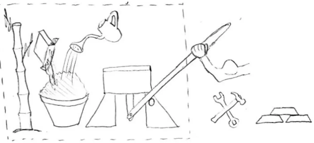
Figure 7 is the boundary sketch, a visual representation of which materials, objects, and systems are either available and under the team’s control and which are out of the team’s control. The objects within the box represent those that can be manipulated, and those outside represent the opposite. As can be seen, soil moisture level and mixture, previous CVBT block press designs, and generic bamboo are available and can be easily manipulated and utilized. The strength of the user, the tools used for manufacturing, and the specific materials of the press, however, are objects outside of the team’s control. In other words, the team is constrained to specific materials and tools that are used in the CVBT workshop.
Figure 7. Boundary Sketch
3.3 Customer Wants and Needs
The newly designed block press is expected to be safe, easy, and inexpensive to manufacture (total cost to manufacture: 2000 Baht or ~$62) given the tools available in the CVBT workshop in Thailand, intuitive to use, have a lifespan of at least 60,000 blocks (5000 blocks per house, 12 houses), and have detailed models and drawings for ease of manufacture. It is necessary that the weak points on the existing BP9 design are either reinforced or redesigned. These weak points include binding in the press carriage, bending of the handle-eccentric interface, and high friction in the press carriage. The new design must be able to create 1/4 scale full, half, and channel blocks that will be used to build model homes or as souvenir bricks. This also necessitates a list of appropriate soil mixes depending on what type of block is being pressed. The main characteristics of the soil to be focused on are color, texture, mixability, compressibility, ease of ejection from the press, and ease of lifting from the press without breakage. It is desired that bamboo is included in the new press design because it is beneficial to the environment.
3.4 Quality Function Deployment (QFD)
3.5 Engineering Specifications
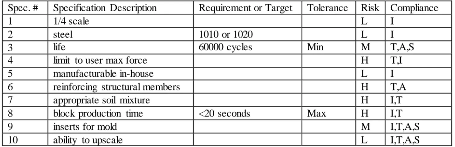
The engineering specifications are shown in Table 1 below where “Risk” represents how difficult it will be to achieve each specification (L=low, M=medium, L=Large) and “Compliance” represents how each specification will be achieved (I=inspection, T=testing, A=analysis, S=similarity). Here are short descriptions of each specification and their difficulty of implementation:
• 1/4 scale: The desired scale compared to the full scale BP 6
• Steel: Main material used to build press that is easily acquired
• Life: Amount of press cycles until a component fails
• Limit to max force: A way to prevent the user from overexerting force and damaging the press. This will be much more of a design challenge because the preexisting BP9 does not include this feature.
• Manufacturable in-house: Part manufacture and assembly must be done using the tools available in CVBT’s machine shop
• Method of reinforcing structural members: Strengthening or redesigning weak points on previous BP9 press design. This will be a challenge, as it could entail a complete redesign of the BP9, and numerous tests.
• Appropriate soil mixture: Creating and experimenting with different soil/clay/cement mixtures that satisfy color, texture, mixability, compressibility, ease of ejection, ease of lifting without breakage. This will be a difficult challenge because of the many factors that can be adjusted to create a functional mixture. Many tests will be needed.
• Block production time: The time required to pack the soil, compress, and extract the block formed
• Inserts for mold: inserts or “frogs” that can be quickly added and removed from the press in order to create full, half, and channel blocks. Ideas for these inserts already exist for the BP9 and the full scale BP6.
• Ability to upscale: The processes to manufacture the 1/4 scale model should be repeatable on full size parts
Table 1. Engineering Specifications Table
Spec. # Specification Description Requirement or Target Tolerance Risk Compliance
1 1/4 scale L I
2 steel 1010 or 1020 L I
3 life 60000 cycles Min M T,A,S
4 limit to user max force H T,I
5 manufacturable in-house L I
6 reinforcing structural members H T,A
7 appropriate soil mixture H I,T
8 block production time <20 seconds Max H I,T
9 inserts for mold M I,T,A,S
4.0 Concept Design
4.1 Considered Designs
The design process began with two brainstorming sessions. The objective was to brainstorm possible concepts that could compress a block of soil (with defined length and width dimensions) in the vertical direction. After the brainstorming sessions, concepts that were too time consuming, complex, or unrealistic to implement were discarded. This left five pressure concepts and three extraction techniques that could be converted to actual designs. Figures 8 through 13 provide visuals and descriptions of the top five concepts.
Figure 8. Traditional Press and Lever and Pivot Extraction (CVBT BP10) [6]
The BP10 applies the traditional press method and the lever and pivot extraction method shown in Figure 8. This is by far the most common design for pressing and extraction of compressed earth blocks, as the research indicates. CVBT’s BP6, BP9, and BP10 all incorporate the basic principles of what is shown above. The basic process is as follows: The soil mixture is loaded into the block carriage and the lid is closed. The lever is rotated to the left over the top of the block carriage to vertical (lever is perpendicular to the press lid). The eccentric contacts the curved tracks located on the top of the lid. The lever directly connected to the eccentric should then continue to be rotated over the top of the block carriage until reaching the lever stopper (lever is parallel with the lid of the press). This second rotation should cause the press linkage to rise upwards and compress the block. To extract the block, the lever is rotated back over the top of the press and placed back in its starting position. The lid can then be lifted, exposing the top of the block to the air. The lever is rotated downward, pivoting about the extraction pivot. This causes the press linkage to rise once again. This time, the press linkage rises until the block is fully exposed to the air on five sides (excluding the bottom).
Lever
Block Carriage
Eccentric
Press Linkage
Lever Stopper
Because this design is so historically reliable, the team considered keeping its basic features and improving them through structural reinforcement and improved manufacturing and assembly procedures. During the narrowing process, it was decided that designing a new and unique style press was more desirable than improving upon the “old, tried and true” design; an original press design brings a new perspective on how to most efficiently press a brick with only human power, hopefully inspiring future innovation.
Figure 9 shows a simple design which would be compressed directly by hand and extracted via a removable base. This design was intended to be especially simple and inexpensive to manufacture. The process is as follows: The soil mixture is loaded into the block carriage. Then the lid is pressed down onto the soil by hand, using the handle attached to the lid. The lid is removed, and the sides of the block carriage, which are all one piece, are lifted off. The block is then lifted off the base. This design, while being very inexpensive, would be ineffective. CVBT indicated that a similar design had been attempted and did not work out well. This is because without mechanical advantage, it is difficult to press the block by hand. In addition, it is difficult to control the amount of force and the distance the block is pressed.
A third design that was considered is the Astram Block Press design [Figure 10], which incorporates a similar concept to that of the traditional block press, with a few differences. The process is as follows: First, the lid is latched closed externally using a locking mechanism instead of rotating the lever over the lid (latch not shown in figure). The lever is pulled down, rotating about the pivot. This causes the base plate to rise, compressing the mixture against the closed lid. When the mixture is fully compressed, the lid is opened, and the lever is pulled down further, raising the base plate until it is flush with the top of the box, allowing the block to be easily removed. A foot pedal in place of a hand lever was also considered as a design innovation for ease of use. There are several flaws to this design, however. The first is that it is very easy to damage the lever. Without a mechanism to warn users from over rotating the lever, it would be very easy to bend the lever during compression. Another issue that arises is that there is nothing stopping the lever from sliding back down to its starting position when the user is unlatching the lid between the pressing and extracting steps of the process. The point of this press was to make the press/extraction process into one fluid, single step, so if the lever returns to its starting position between the two main steps, then the purpose has been defeated.
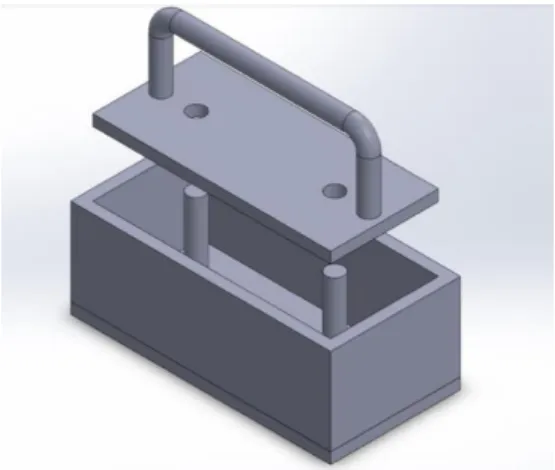
Figure 11 was named the “floor pump crank” design because of its similarities to a bicycle floor pump. This press uses an eccentric attached to a rotating crank to compress the soil. The crank is able to be lifted in a slot in order to extract the block. The procedure is as follows: The soil mixture is loaded into the block carriage and the lid is latched shut (latch not shown in figure). The eccentric’s lowest point should be in contact with the base plate/eccentric interface initially. The crank is then rotated 360 degrees in either direction which causes the base plate to rise, guided by the base plate guides, pressing the soil mixture into the underside of the lid. The block is now compressed. The lid is unlatched and opened at this point. To extract the block, the crank extensions are lifted, and the crank slides up the slot, lifting the base plate and block to the top of the block carriage. The block is now exposed and can be carefully removed.
Figure 11. Floor Pump Crank Press (FPCP)
Eccentric
Block Carriage
Base Plate
Guides
Base Plate/Eccentric
Interface
Hand Crank
Figure 12 shows the internal components of the design. The Floor Pump Crank Press (FPCP) should be mounted to the corner of a table for ease of use. This is a limiting factor of this design, as it cannot be used on a floor or the middle of a table. This is because the lever arm is longer than the legs of the press, and the crank must be turned a full rotation. This could be solved by making the legs longer, but this would also necessitate larger feet in order to reduce the possibility of tipping. This design was at one point considered to be the final design, but the largest flaw with this design is that it will be a very poor design if up-scaled to full size because of the extraction method. Anything larger than a ¼ scale block press necessitates mechanical advantage to extract the block. The floor pump crank press does not implement a lever for block extraction, making it an unrealistic design to up-scale. Therefore, another design was developed.
A similar concept to the floor pump crank press is the eccentric crank shaft press and big eccentric extraction method shown in Figure 13. This unconventional press and extraction technique involves a crank (rather than a lever) to apply enough force to both press and extract the block in one crank rotation. The process is as follows: The soil mixture is loaded into the block carriage and the lid is latched shut (latch not shown in figure). The hand crank is rotated clockwise, causing the press eccentric to contact the base plate/eccentric interface, thus lifting the base plate and pressing the soil between the lid and the base plate (base plate is located inside the block carriage and is the surface that the block sits on). At this point, the crank has been rotated 180 degrees, and the block has been fully compressed. The lid is unlatched and lifted. The crank continues its rotation clockwise, causing the big extraction eccentric to contact the base plate/eccentric interface. The small press eccentrics lose contact with the base plate/eccentric interface, and the extraction eccentric presses the base plate upward until it is flush with the top of the block carriage. The earth block should now be exposed to the air on five of its sides (excluding the bottom) and can be easily removed.
Figure 13. Eccentric Crank Shaft Press and Big Eccentric Extraction
This design was initially eliminated because calculations determined that the extraction eccentric would have to be too large to be feasible, but it was determined that these calculations were incorrect. After meeting with the sponsor and other discussions, it was determined that it would be preferable that the compression and extraction are done in separate motions. In addition, the interfaces and the eccentrics would have a lot of friction between them. Finally, it was decided that it was preferable to have the compression and extraction occur along one single cam profile rather than two separate eccentrics. Solutions to these problems resulted in the final design, which is detailed below.
Extraction Eccentric
Press Eccentric
Base Plate/
Eccentric Interface
Block Carriage
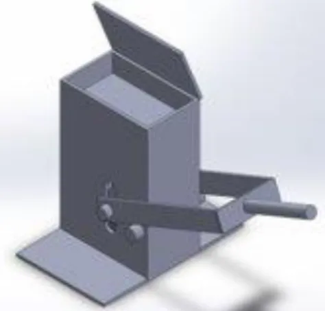
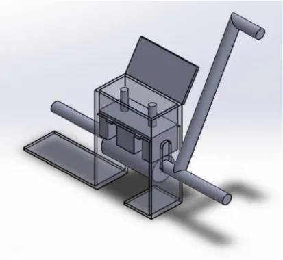
Figure 14 shows a concept known as the cam crank. This method of compression and extraction implements ideas from the eccentric crank shaft press and big eccentric extraction of Figure 13 and from the FPCP of Figure 11. The procedure is as follows: While the base plate is located at its lowest point, the soil is added in the block carriage. The lid is closed and latched. The crank is then rotated 110 degrees counterclockwise until the lever tip contacts the working surface. This action compresses the soil as the wheels on the base plate are lifted by the cam profile. The lever is brought back to the center to relieve the lid of excess pressure. The lid can then be unlatched. The block surface is now exposed to the air, and the lever can be rotated 110 degrees clockwise. The larger end of the cam profile presses upward on the base plate wheels, and the block is lifted out of the block carriage. This design also incorporates a hinge and a latch, which had not been designed for any of the previous designs.
Figure 14. Cam Crank Press
4.2 Design Selection
Table 2. Pugh Matrix for Compression Technique
Table 3. Pugh Matrix for Extraction Technique
5.0 Final Design
Through extensive research, redesign, and discussion with the sponsor, the cam crank block press design was chosen as the final design as it best satisfies the customer requirements. Figures 15 and 16 detail the external and internal components of this design. By reducing the amount of moving parts and fasteners, this redesign achieves simplicity and durability. In addition to reducing part costs due to having fewer parts, design simplification also makes manufacturing, assembly, and disassembly easier, which reduces labor costs. Thus, the total product cost is reduced in both categories. All parts can be manufactured and assembled in-house (besides fasteners) which is a necessary design consideration as these presses will be produced in Thailand where access to specialized stock parts is limited. Also, unlike many of the other considered press designs, the cam crank press design has the potential to be up-scaled to a full-scale press. One reason is that the lever arm does not need to rotate 360 degrees, meaning that the lever does not need to hang off the edge of a table. Because a full-scale press would necessitate a lever length of at least 4 ft, it is important that the lever pivot point is located low enough so that the operator can always reach the end of the lever. This means that a lever that must rotate 360 degrees to complete a press cycle must also hang off the edge of a table to function thus raising the lever pivot point and making it very difficult to operate. The cam crank press design solves this problem by rotating a total of 220 degrees. Another unique aspect of this press design is the mechanism of attachment between the cam subassemblies and the crankshaft; cotter pins slide though the cam collar and crankshaft holes to fasten them together. This feature not only allows for simple assembly and disassembly for part replacement and repair but also acts as a fail-safe in the case of force overload. In other words, the cotter pins will shear off long before any of the other components will even bend. See Appendix 4 for a detailed description of how to use the cam crank block press design.
Baseline (BP10) Weight
Requirements Big Eccentric Sliding Crank Cam Crank Shaft Lever and Pivot
Durable 0 5 1 0 1 0
Easy to Manufacture 0 3 0 1 -1 0
Easy to use 0 4 -1 1 1 0
Safe 0 3 0 1 1 0
2000 Baht 0 2 0 1 1 0
Productivity 0 3 1 0 1 0
Up-Scale Potential 0 3 0 -1 0 0
Bamboo 0 1 0 0 0 0
Totals 4 9 14 0
Extraction Technique
Baseline (BP10) Weight
Requirements Eccentric Crank Shaft Traditional Press Hand Press Foot Pedal Cam Crank Shaft One Directional Rotation
Durable 0 5 1 0 1 -1 1 0
Easy to Manufacture 0 3 1 0 1 -1 -1 0
Easy to use 0 4 0 0 1 1 1 1
Safe 0 3 1 0 -1 -1 1 1
2000 Baht 0 2 1 0 1 0 1 0
Productivity 0 3 0 0 -1 1 1 0
Up-Scale Potential 0 3 0 0 -1 0 1 1
Bamboo 0 1 0 0 0 0 0 0
Totals 13 0 5 -4 17 10
Figure 15. Cam Crank External Components
Figure 16. Cam Crank Internal Components
Latch Hooks
Latch Rod
Block carriage
Lid
Baseplate guides
Crank
Cams
Wheels
Baseplate
Cam Collars
Cotter Pins
6.0 Manufacturing Plan
Because the CVBT Thailand workshop does not have easy access to purchasing stock parts (besides fasteners), all parts must be manufactured and assembled in-house. The Blockheads’ techniques for manufacture and assembly may differ from those of CVBT Thailand; however, the press is designed and toleranced in such a way that allows for a wide range of tools to be used to complete the design. The Blockheads’ manufacturing and assembly plans are outlined below. See Appendix 6 for parts reference.
6.1 Procurement
Most of the steel plate and steel rod will be purchased from Online Metals due to its cheaper cost compared to other steel-supplying companies. It should be noted that for ease of manufacturing in Thailand, the rods will be kept at their standard diameter; no turning is necessary. As a result, one rod will be purchased from McMaster-Carr. This is because even though rods bought from McMaster-Carr are more expensive than Online Metals, McMaster-Carr sells the desired diameter rod where Online Metals does not. In addition, all fasteners will be bought from McMaster-Carr because of its diverse assortment of fasteners. The total cost will be around $63. For a full breakdown of the costs, see Appendix 6.
6.2 Manufacturing
1. Side Walls*
a. Cut from 6.35mm plate to a tolerance of at most 2mm using bandsaw Equipment: vertical bandsaw
2. End Walls*
a. Cut from 6.35mm plate to a tolerance of at most 2mm using bandsaw b. Drill holes for lid hinge and cam shaft using drill press
c. Drill countersink hole for dowel bolt Equipment: vertical bandsaw, drill press
3. Baseplate Guide Connection Pieces*
a. Cut from 3.175mm plate to a tolerance of at most 2mm using bandsaw b. Drill hole for baseplate guide using drill press
Equipment: vertical bandsaw, drill press
4. Base Plate Extrusions*
a. Cut from 6.35mm plate to a tolerance of at most 2mm using bandsaw b. Drill hole for dowel using drill press
Equipment: vertical bandsaw, drill press
5. Baseplate Guides
a. Machine out 5.5mm hole from 12.7mm rod using lathe
b. Turn rod diameter down to 8.5mm with a tolerance of at most 1mm using lathe c. Part a length of 30mm with a tolerance of at most 2mm using lathe
Equipment: lathe
6. Lid*
Equipment: vertical bandsaw
7. Hinge
a. Machine out 5.5mm hole from 22mm rod using lathe
b. Turn rod diameter down to 19mm with a tolerance of at most 1mm using lathe c. Part a length of 75mm with a tolerance of at most 2mm using lathe
Equipment: lathe
8. Base Plate*
a. Cut plate from 3.175mm plate to a tolerance of at most 2mm using bandsaw b. Drill holes for baseplate guides using drill press
Equipment: bandsaw, drill press
9. Cam*
a. Tape full scale picture to 6.35mm plate
b. Cut as close as possible to nominal dimensions using vertical bandsaw
c. Clamp the two cams together using vise grips
d. File or grind the excess metal to achieve the desired profile (it is important that both cams have the same exact profile)
e. Drill hole for cam shaft using drill press
f. More filing of cam profile may be necessary after full assembly and testing Equipment: vertical bandsaw, file, drill press, grinding wheel
10. Camshaft
a. Bend 12.7mm rod by placing it in a vice, heating a small section with oxyacetylene torch, and bending the rod by pushing the end of the rod until the bend is 90 degrees
b. Cut off remaining length using chop saw
c. Drill cottar pin holes perpendicular to the bend using drill press Equipment: oxyacetylene torch, chop saw, drill press
11. Wheels
a. Machine out a 5.5mm hole from 12.7mm rod using lathe
b. Part a length of 27.9mm with a tolerance of at most 2mm using lathe Equipment: lathe
12. Collars
a. File surface where small hole will be drilled until flat b. Drill cottar pin holes using drill press
c. Machine out a 12.7mm hole from 22mm rod using a lathe
d. Part a length of 17mm with a tolerance of at most 2mm using a lathe Equipment: file, drill press, lathe
13. Latch Hooks*
a. Drill bottom hole for latch bolt and top hole for lid-latch connection rod with drill press (the distance between these holes is the most important dimension)
c. Cut as close as possible to nominal dimensions using vertical bandsaw d. File or grind the excess metal to achieve the desired profile
e. More filing may be necessary after full assembly is complete Equipment: vertical bandsaw, drill press, file, grinding wheel
14. Foot
a. Cut from 3.175mm plate using a chop saw Equipment: Chop Saw
*A second option is to get a close cut using an angle grinder with a cutting wheel and then grind off the excess material on the grinding wheel for precision
6.3 Assembly
I. Subassemblies
1. Body Subassembly
a. Place side walls and end walls up against the wood block fixture
b. Insert wood wedge until both side walls are firmly pressed against the wood block c. Use a single clamp to firmly press end walls into the end faces of the wood block d. Use MIG welder to tack all walls in place
e. Place baseplate guide connection pieces in wood block grooves and MIG weld tack them in place
f. Remove the tacked body from the wooden fixture
g. Complete the body by MIG welding all tacked exterior t-joints and butt joints (no welds inside of the block carriage)
h. MIG weld the foot to the base of the end walls
2. Baseplate Subassembly
a. Clamp base plate extrusions to the baseplate b. MIG weld all t-joints
3. Lid Subassembly
a. Clamp hinge to lid so that the faced side of the cylinder is coincident with the lid surface b. Clamp lid-latch connection rod to the top of the lid
c. MIG weld hinge and lid-latch connection rod to lid
4. Cam Subassembly
a. To orient cams, slide the two cams and collars onto the cam shaft and insert cottar pins through pin holes in collars and pin holes in shaft
b. Rotate cams to the correct orientation making sure that they are matched with each other c. Using vise grips, clamp collars to cams
d. Remove cottar pins and MIG weld collars to cams
II. Full Assembly 1. Cam Shaft to Body
a. Insert bushings into the shaft holes in the end walls of the body
b. Insert cam shaft into cam shaft hole in end wall and the two cams (welded to the collars) in line with the cam shaft holes so that the cams can be slid onto the cam shaft
c. The cam shaft should exit out the opposite end wall cam shaft hole
d. Align the cottar pin holes in the collars with the pin holes in the cam shaft as pictured in Figure 18. Insert cottar pins.
e. It is crucial that this assembly is done first
2. Baseplate to Body
a. Slide baseplate into block carriage of the body
b. Align dowel holes in base plate extrusions with dowel holes in the end walls
c. Hold wheel in line with dowel holes and insert dowel through dowel holes and both wheels in their respective locations
d. When the dowel is fully inserted, the baseplate should be free to drop in the block carriage
e. It is crucial that this assembly is done second
Figure 20. Dimetric Assembly of Baseplate and Body
3. Latch Hooks to Body
a. Align latch hook holes and M5 washers with dowel holes in end walls
b. Insert M5 x 0.8 x 20mm flat hex bolts from inside end walls to outside with heads in countersunk holes
f. Add M5 washers and M5 x 0.8mm opposing nuts making sure to leave bolts loose enough to be able to rotate the latch hooks
Figure 21. Dimetric Assembly of Latch Hooks and Body
4. Baseplate Guides to Body
a. Slide baseplate guides onto M5 x 0.80 x 50mm hex bolt and insert bolts through holes in baseplate guide connection pieces
b. Slide M5 washers onto the end of the bolts and tighten on M5 x 0.8mm opposing nuts c. Nuts should not be tightened all the way to allow baseplate guides to have a bit of play
Figure 22. Front View Assembly of Baseplate Guides and Body
5. Lid Hinge to Body
a. Place lid subassembly flat on top of the body covering the block carriage so that the hinge connected to the lid aligns with the hinge holes on the end walls
Figure 23. Dimetric Assembly of Lid and Body
6. Baseplate Extrusion Guides to Body
a. Because of accumulated tolerance error the baseplate may have a slide issue with binding in the block carriage. The baseplate subassembly should not wiggle from front to back in the carriage. For this reason, baseplate extrusion guides are added.
b. Clamp on guides using vise grips and slide baseplate up and down to ensure that the guides (in their current locations) have fixed the binding issue (baseplate assembly should not wiggle from front to back when pressing and pulling on baseplate extrusion from the front of the press). Adjust guide positions until the issue is fixed.
c. MIG weld guides to body in current positions
d. If press still does not press or extract correctly, make sure that the this is not due to rough cams edges or incorrect cam profiles. If this is the problem, file or grind cams until the press functions correctly.
6.4 Safety
The block press has inherent safety hazards such as pinch points and unsafe use. Corrective actions have been taken to eliminate or mitigate the chance for injury. Refer to Appendix 5 for a list of potential hazards and the precautions taken to limit them.
6.5 Maintenance
The block press has three moving components: the baseplate, the camshaft, and the lid hinge. As a result, these three components have the highest chance of failure. To reduce the likelihood of failure occurring due to friction, lubrication will be applied to the inside walls of the block carriage and the lid hinge every 10 cycles. For the camshaft, because it rotates within the bushings located on both end walls, the bushings will be regularly greased with bearing grease. This will reduce possible damage done to either the bushings or the camshaft. Washers have been placed on all bolts to prevent damage to the bolt heads and press’s body. The washers will eventually wear out due to friction, but the washers can easily be replaced as the subassemblies in which the washers are located can be disassembled.
6.6 Repair
The entire assembly can be easily disassembled, and each subassembly can be independently repaired or replaced. This can be performed as follows:
1. Lid
• Remove nuts and bolt
• Repair or replace fasteners or lid subassembly 2. Baseplate
• Remove baseplate guides
• Remove latch hooks
• Lift baseplate until wheel axle aligns with the latch hook holes
• Extract dowel by tapping a drift punch through latch hook hole thus pushing wheel dowel out the opposite side
• Lift baseplate out of carriage
• Replace or repair baseplate, wheels, or dowel as needed 3. Crankshaft/ Cams
• Remove both cotter pins
• Slide cam subassemblies off crankshaft while pulling crankshaft from bushings
• Replace or repair crankshaft, cam subassemblies, or cotter pins
7.0 Design Verification
*See Test Plan in Appendix 9 for descriptions of component testing.
7.1 Test Results
To assess the functionality and durability of the block press, four tests were done:
weakest components in the block press, so it was decided that the cotter pins and cotter pin holes diameters should be slightly increased. A positive of the weak cotter pins is that they will always break before any of the other components do. This will save time and money as the cotter pins are very cheap and easy to replace.
The third test evaluated the durability of the components and welds of the press. For this test, the block press was dropped from four feet above the work surface, then inspected for damages. This test was repeated three times. The only damages were on the corners of the press, which were slightly dented. No welds or other components were damaged during the drops, so it was determined that the press’s integrity would not be at risk if it was dropped.
The last test determined the number of cycles that could be done before the press needed to be re -lubed. To perform this test, the carriage walls were lubricated with WD40 and the press was used to press and extract multiple bricks until either the compression or extraction process became too difficult to perform. This process was repeated three times, and the average number of cycles before re -lubrication was 10 cycles.
7.2 Design Changes
Based on the results of the Test Plan, the following changes have been proposed to improve the functionality and reliability of the block press:
1. The diameters of the cotter pin and cotter pin holes in the collars and crankshaft should be increased from 3/32” to 1/8”. This is to decrease the chance of the cotter pins shearing off in the event of overloading the carriage.
2. Rubber end caps should be placed on both ends of the lid-latch connection rod. This is because when extracting the block, the user’s hand can scrape against the end of the rod, which can cause injury.
8.0 Project Management
Listed below is a chronological map of how the Blockheads will go about designing and producing their product. As can be seen, the process involves repetitive testing and continuous iteration of design.
• Define Problem
• Background Research
o Interview users
o Use BP6 and BP10 on Cal Poly campus
o Research preexisting designs
• Present Probable Solutions
o Brainstorm
o Pugh Diagram
o Project Direction Selection
o Concept Model
o Structural Prototype
• Test Structural Prototype
o If design fails to solve the problem:
▪ Background research and present more solutions
o If design succeeds:
▪ Test again to see if new problems arise
• If design causes more problems:
o More research and solutions
o Implement solutions
• Go into Production
o Test final product
▪ Research and provide solutions to issues that arise
• Final Tests
• Present Final Product
8.1 Timeline
Table 4. Important Checkpoints and Dates Key Deliverables
Deliverable Due Date
Preliminary Design Review March 8 Interim Design Review April 11 Critical Design Review May 3
All Parts Ordered May 16
Manufacturing and Test Review Poster May 31 Confirmation Prototype October 22 Final Design Review (Expo) November 22
9.0 Conclusion
The CVBT BP9 compressed earth block press is due for a redesign; there is too much friction when used, it has several weak points due to users unintentionally applying excessive force, and it is too expensive to manufacture. The Blockheads were able to successfully complete said redesign converting the old lever-piston design into a cam-crank design. This design has less moving parts resulting in less friction and more intuitive operation. In addition, the use of thicker materials ensures that critical components are not weak points. Finally, because the design changes resulted in using simpler components, the desired press cost of $62 was nearly met. However, with a cheaper materials provider and purchasing in bulk, the Blockhead’s final press cost of $63 can be further reduced. It should be noted that this final cost does not include labor costs. The Blockhead’s were unfortunately unable to achieve all of the customer specifications due to a completely new design direction. The new press design does not yet have the capability of creating half or channel bricks. In addition, the one obvious weak point is the cotter pins. These can shear off if the user applies too much force due to excess material in the block carriage. However, it is preferable that these components should break as they are much cheaper and easier to replace than other critical components.
9.1 Next Steps
Because this design is unique, it provides CVBT Thailand with a new design direction to explore. One important improvement that should be made is that the cotter pin and cotter pin hole diameters should be increased as to improve its resistance to shearing. However, the diameter will remain small enough that these components will still act as fail-safes. Also, all threaded fasteners can be replaced with cotter pin bolts. Finally, the press was not designed to create half and channel bricks; these brick options can be easily implemented. Once these improvements are added, the design can be scaled up and tested to determine the viability of the design at full scale.
Works Cited
[1] “Soil Block Presses”. Humanity Development Library 2.0. 1988. The New Zealand Digital
Library. http://www.nzdl.org/gsdlmod?e=d-00000-00---off-0hdl--00-0----0-10-0---0---0direct-10---4---
-0-0l--11-en-50---20-about---00-0-1-00-0--4----0-0-11-10-0utfZz-8-10&cl=CL1.16&d=HASH4edbf917bee4e6ae86aa2c.23&gc=0.
[2] “Small-Scale Manufacture of Stabilized Soil Blocks”. Community Development Library. 1987, chap IV, sec VII. The New Zealand Digital
Library. http://collections.infocollections.org/ukedu/uk/d/Jh2380e/6.7.1.html. [3] Miles, John. Making Building Blocks with the CINVA-Ram Block
Press. 1966. https://arc456.files.wordpress.com/2015/02/making-building-blocks-with-earth.pdf
[4] Centro de Experimentación en Tecnología Apropiada. The CETA-RAM Block
Press. http://www.ecohabitar.org/wp-content/uploads/2015/10/The-CETA-RAM-Block-Press.pdf
[5] “BP9 Block Press”. The Center for Vocational Building Technology, 2018. https://www.cvbt-web.org/BP9-BLOCK-PRESS.
[6] Brown, Jordan; Evans, Michael; Morrow, Connor. Model Block
Press. 2014. https://digitalcommons.calpoly.edu/cgi/viewcontent.cgi?referer=&httpsredir=1&article=126 0&context=mesp.
Appendix 4. Operation Manual
1) Unlatch and open the lid.
a. Rotate latch hooks off the latch rod so that they hang below their pivot points.
2) Ensure the lever is in the vertical starting position. a. The wheels should sit in the notch in the cam profile.
b. This is important for maintaining a consistent compression distance to yield consistent blocks.
3) Load the correct soil mixture into the block carriage.
a. Make sure that the top faces of the baseplate guides and the tops of the block carriage walls are not covered in dirt.
4) Close and latch the lid.
5) Press a brick.
a. Rotate the lever counter clockwise until the tip of the lever reaches the working surface (~110deg). i. The wheels function as the cam-followers as they run along the profile of the cam. As the lever
rotates counter-clockwise, the wheels are forced upward thus lifting the baseplate and pressing the soil mixture.
6) Return the lever to the vertical starting position.
a. The wheels will, again, sit in the notches on the cam profiles. b. This relieves pressure on the lid so that the lid can be unlatched.
7) Unlatch and open the lid.
8) Extract the block.
a. Rotate the lever clockwise until the tip of the lever reaches the working surface (~110deg)
i. The base plate will again be lifted. This time the base plate will rise until its surface is flush with the tops of the block carriage walls thus exposing the compressed block to the air on all sides.
9) Reset the block press to the starting position.
a. Rotate the lever back to the vertical starting position.
Appendix 5. Design Hazard Checklist
Y N
1. Will the system include hazardous revolving, running, rolling, or mixing actions?
2. Will the system include hazardous reciprocating, shearing, punching, pressing, squeezing, drawing,
or cutting actions?
3. Will any part of the design undergo high accelerations/decelerations?
4. Will the system have any large (>5 kg) moving masses or large (>250 N) forces? 5. Could the system produce a projectile?
6. Could the system fall (due to gravity), creating injury?
7. Will a user be exposed to overhanging weights as part of the design? 8. Will the system have any burrs, sharp edges, shear points, or pinch points? 9. Will any part of the electrical systems not be grounded?
10. Will there be any large batteries (over 30 V)?
11. Will there be any exposed electrical connections in the system (over 40 V)?
12. Will there be any stored energy in the system such as flywheels, hanging weights or pressurized
fluids/gases?
13. Will there be any explosive or flammable liquids, gases, or small particle fuel as part of the
system?
14. Will the user be required to exert any abnormal effort or experience any abnormal physical posture
during the use of the design?
15. Will there be any materials known to be hazardous to humans involved in either the design
or its manufacturing?
16. Could the system generate high levels (>90 dBA) of noise?
17. Will the device/system be exposed to extreme environmental conditions such as fog, humidity, or
cold/high temperatures, during normal use?
18. Is it possible for the system to be used in an unsafe manner? 19. For powered systems, is there an emergency stop button?
20. Will there be any other potential hazards not listed above? If yes, please explain on reverse.
Description of Hazard
Planned Corrective Action
Planned
Date
Actual
Date
Revolving Crank
Safety guard so that no one can put their fingers
under the cam during rotation
May 31
Falling off table
Attach wide feet to reduce risk of toppling. Fasten to
table.
May 31
Pinched by the lid
Tight tolerance on the hinge so the lid is not affected
much by gravity.
May 31
Press and extraction
physical exertion
Locate press on edge of table at waist height for
most ergonomic positioning.
May 31
Unsafe use
Create a clear list of directions to use the press.
May 31
Appendix 8. DVP&R
Team: Blockheads
Quantity Type Start date Finish date Test Result Quantity Pass Quantity Fail 1
Crank/ lift base plate
Press and extract at least 20 bricks
completes tasks with smoothly with constant resistance
Chester Wong FP 30 Sub 11/7/2019 11/7/2019 Success 30 0 Press is difficult to operate after 10 cycles
2 Crank/ Ergonomic to use
Press and extract at least 20 bricks
user does not feel discomfort in any part
of the body (besides tiredness)
Ben van Hamersveld
FP 30 Sub 11/7/2019 11/7/2019 Success 30 0
3
Crank/ Provide mechanical advantage
Press and extract brick by simply pressing up on baseplate with fingers, then using the crank
using the crank requires much less
effiort
Alex Giannousis
FP 30 Sub 11/7/2019 11/7/2019 Success 30 0
4 Carriage/ Hold soil without leaking
Press and extract at least 20 bricks
soil must stay in carraige and not leak
Chester Wong FP 30 Sub 11/7/2019 11/7/2019 Success 30 0
5 Carriage/ Slide smoothly
Press and extract at least 20 bricks
completes tasks with smoothly with constant resistance
(minimal binding)
Ben van Hamersveld
FP 30 Sub 11/7/2019 11/7/2019 Success 30 0
6 Lid/ rotates smoothly
Press and extract at least 20 bricks
lid must open and close smoothly everytime without being hindered by soil
Alex Giannousis
FP 30 Sub 11/7/2019 11/7/2019 Success 30 0
7 Lid/ latches tightly Press and extract at least 20 bricks
lid remains tightly shut every repetition
Chester Wong FP 30 Sub 11/7/2019 11/7/2019 Success 30 0
8
Support legs/ support press during process
Press and extract at least 20 bricks
legs should never visually bend
Ben van Hamersveld
FP 30 Sub 11/7/2019 11/7/2019 Success 30 0 DVP&R Engineer: Description of System: Model Block Press
Senior Project DVP&R
TEST PLAN TEST REPORT
Date: 10/25/2019 Sponsor: CVBT Thailand
Item
No Specification # Test Description Acceptance Criteria
Test
Responsibility Test Stage
SAMPLES TIMING TEST RESULTS
16
7
5
2
8
6
10
3
11
4
13
14
12
Scale:1:4
Part: BODY SUBASSEM. Dwg. #: 100000
Drwn. By: The Blockheads Date: 11/14/2019
ME 430 - Fall 2019
X.XX ± 0.5Material: CRS
Chkd. By: ME STAFF TOLERANCES
IN MM: X ± 3.0 X.X ± 1.0
1
101001
LID SUBASSEMBLY
1
2
101002
BODY SUBASSEMBLY
1
3
101003
BASEPLATE SUBASSEMBLY
1
4
101004
CAM SUBASSEMBLY
2
5
101005
M5x 0.80x100mm HEX BOLT
1
6
101006
M5x 0.80x50mm HEX BOLT
2
7
101007
M5x 0.80x30mm FLAT HEX BOLT
2
8
101008
Oil-Embedded Bushing 1/2"
2
9
101009
M5 Washer
8
10
101010
M5x 0.80 Nut
10
11
101011
3/32" HAMMERLOCK COTTER PIN
2
12
101012
REBAM ROD/GUIDE
2
13
101013
LATCH HOOKS
2
14
101014
CAM SHAFT
1
15
101016
WHEELS
2
ME 430 - Fall 2019
Material: CRS Date: 11/14/2019 Chkd. By: ME STAFF Drwn. By: The Blockheads Dwg. #: 100000Part: BODY SUBASSEM. Scale:1:4
1
3
.25
6.4
[Inches]
Millimeters
ITEM NO.
PART NUMBER
DESCRIPTION
QTY.
1
102000
LID HINGE
1
2
102001
LID
1
3
102002
LID-LATCH CONNECTION
1
Cal Poly Mechanical Engineering
ME 430 - Fall 2019
Scale:1:1Part: LID SUBASSEMBLY Dwg. #: 101001
Drwn. By: The Blockheads
Date: 11/14/19 Chkd. By: ME STAFF
Material: CRS TOLERANCES
IN MM: X ± 3.0 X.X ± 1.0 X.XX ± 0.5
2.95
75.0
.75
19.0
[Inches]
Millimeters
Part: LID HINGEScale:1:1
TOLERANCES IN MM:
X ± 3.0 X.X ± 1.0 X.XX ± 0.5
Cal Poly Mechanical Engineering
ME 430 - Fall 2019
Dwg. #: 102000Drwn. By: The Blockheads
Date: 11/14/2019 Chkd. By: ME STAFF
Material: 19.05mm (0.75") DIA. CRS
1.18
30.0
2.91
73.9
.25
6.4
[Inches]
Millimeters
Material: 3.175mm (0.125") THK CRSChkd. By: ME STAFF Date: 11/14/2019
Drwn. By: The Blockheads Dwg. #: 102001
ME 430 - Fall 2019
Cal Poly Mechanical Engineering TOLERANCES
IN MM: X ± 3.0 X.X ± 1.0 X.XX ± 0.5
Scale:1:1 Part: LID
[Inches]
Millimeters
Cal Poly Mechanical EngineeringME 430 - Fall 2019
Scale:1:1Part: LID-LATCH CONNECTION Dwg. #: 102002
Drwn. By: The Blockheads
Date: 11/14/19 Chkd. By: ME STAFF
Material: 3.175mm (0.125") DIA. CRS TOLERANCES
IN MM: X ± 3.0 X.X ± 1.0 X.XX ± 0.5
5
4
3
1
1.476
37.50
.250
6.35
98
8
[Inches]
Millimeters
ITEM
NO.
NUMBER
PART
DESCRIPTION QTY.
1 102006
FOOT
1
2 102003
SIDE WALL
2
3 102007
BASEPLATE GUIDE
CONNECT
2
4 102004
END WALL LEFT
1
5 102005
END WALL RIGHT 1
Cal Poly Mechanical Engineering
ME 430 - Fall 2019
Scale:3:8Part: BODY SUBASSEM. Dwg. #: 101002
Drwn. By: The Blockheads
Date: 11/14/2019 Chkd. By: ME STAFF
Material: CRS TOLERANCES
IN MM: X ± 3.0 X.X ± 1.0 X.XX ± 0.5
2.95
75.0
[Inches]
Millimeters
Cal Poly Mechanical EngineeringME 430 - Fall 2019
Scale:1:2Part: SIDE WALL Dwg. #: 102003
Drwn. By: The Blockheads
Date: 11/14/19 Chkd. By: ME STAFF
Material: 6.35mm (0.25") THK CRS TOLERANCES
IN MM: X ± 3.0 X.X ± 1.0 X.XX ± 0.5
3.16
80.2
6.76
171.8
2.37
60.2
4.37
111.0
6.39
162.3
1.24
31.5
1.24
31.5
2.80
71.2
5.5 .22 THRU
10.4 0.41 X 90°
[Inches]
Millimeters
Part: END WALL LEFTScale:1:2
TOLERANCES IN MM:
X ± 3.0 X.X ± 1.0 X.XX ± 0.5
Cal Poly Mechanical Engineering
ME 430 - Fall 2019
Dwg. #: 102004Drwn. By: The Blockheads
Date: 11/14/2019 Chkd. By: ME STAFF
Material: 3.175mm (0.125") THK CRS
3.16
80.2
6.76
171.8
2.37
60.2
4.37
111.0
6.39
162.3
1.24
31.5
1.24
31.5
2.80
71.2
5.5 .22 THRU
15.9 58 " THRU
[Inches]
Millimeters
Part: END WALL RIGHT Scale:1:2
TOLERANCES IN MM:
X ± 3.0 X.X ± 1.0 X.XX ± 0.5
Cal Poly Mechanical Engineering
ME 430 - Fall 2019
Dwg. #: 102005Drwn. By: The Blockheads
Date: 11/14/2019 Chkd. By: ME STAFF
Material: 3.175mm (0.125") THK CRS
3.5
88
[Inches]
Millimeters
TOLERANCESIN MM: X ± 3.0 X.X ± 1.0 X.XX ± 0.5
Material: 3.175mm (0.125") THK CRS
Chkd. By: ME STAFF Date: 11/14/2019
Drwn. By: The Blockheads Dwg. #: 102006
Part: FOOT Scale:1:2
ME 430 - Fall 2019
Cal Poly Mechanical Engineering
1.976
50.20
.988
25.10
.276
7.00
.551
14.00
[Inches]
Millimeters
Cal Poly Mechanical Engineering
ME 430 - Fall 2019
Scale:1:1Part: BASEPLATE GUIDE CONNECT. Dwg. #: 102007
Drwn. By: The Blockheads
Date: 11/14/19 Chkd. By: ME STAFF
Material: 3.175mm (0.125") THK CRS TOLERANCES
IN MM: X ± 3.0 X.X ± 1.0 X.XX ± 0.5
1.10
28.0
1.10
28.0
8
8
[Inches]
Millimeters
ITEM NO.
PART NUMBER
DESCRIPTION
QTY.
1
102008
BASEPLATE
1
2
102009
BASEPLATE EXTRUSION
3
Cal Poly Mechanical Engineering
ME 430 - Fall 2019
Scale:1:1Part: BASEPLATE SUBASSEMBLY Dwg. #: 101003
Drwn. By: The Blockheads
Date: 11/14/2019 Chkd. By: ME STAFF
Material: CRS
TOLERANCES IN MM:
X ± 3.0 X.X ± 1.0 X.XX ± 0.5
1.48
37.50
.33
8.50
1.57
40.00
.74
18.75
A
B
[Inches]
Millimeters
0.5
MA B
Material: 3.175mm (0.125") THK CRS
Chkd. By: ME STAFF Date: 11/14/2019
Drwn. By: The Blockheads Dwg. #: 102008
ME 430 - Fall 2019
Cal Poly Mechanical Engineering TOLERANCESIN MM: X ± 3.0 X.X ± 1.0 X.XX ± 0.5
Scale:1:1 Part: BASEPLATE
2.44
62.00
.22
5.50
[Inches]
Millimeters
Cal Poly Mechanical EngineeringME 430 - Fall 2019
Scale:1:1Part: BASEPLATE EXTRUSION Dwg. #: 102009
Drwn. By: The Blockheads
Date: 11/14/2019 Chkd. By: ME STAFF
Material: 6.35mm (0.25") THK CRS TOLERANCES
IN MM: X ± 3.0 X.X ± 1.0 X.XX ± 0.5
2.441 62.00
[Inches]
Millimeters
Cal Poly Mechanical EngineeringME 430 - Fall 2019
Scale:1:1Part: BASEPLATE EXT. GUIDE Dwg. #: 102010
Drwn. By: The Blockheads
Date: 11/14/2019 Chkd. By: ME STAFF
Material: 3.175 mm (0.125") THK CRS TOLERANCES
IN MM: X ± 3.0 X.X ± 1.0 X.XX ± 0.5
1.656
42.05
.740
18.79
12.70 .500 THRU
[Inches]
Millimeters
Material: 6.35mm (0.25") THK CRSChkd. By: ME STAFF Date: 11/14/2019
Drwn. By: The Blockheads Dwg. #: 102011
ME 430 - Fall 2019
Cal Poly Mechanical Engineering TOLERANCESIN MM: X ± 3.0 X.X ± 1.0 X.XX ± 0.5
Scale:1:1 Part: CAM
.68
17.3
3
32 "
2.38
7
8 "
22.2
12.7
[Inches]
Millimeters
TOLERANCES IN MM:
X ± 3.0 X.X ± 1.0 X.XX ± 0.5
Material: 22.2 mm (7/8") DIA. CRS
Chkd. By: ME STAFF Date: 11/14/19
Drwn. By: The Blockheads Dwg. #: 102012
Part: COLLAR Scale:2:1
ME 430 - Fall 2019
Cal Poly Mechanical Engineering
1.18
30.0
.22
5.5
[Inches]
Millimeters
Cal Poly Mechanical EngineeringME 430 - Fall 2019
Scale:2:1Part: BASEPLATE GUIDE Dwg. #: 101012
Drwn. By: The Blockheads
Date: 11/14/19 Chkd. By: ME STAFF
Material: CRS TOLERANCES
IN MM: X ± 3.0 X.X ± 1.0 X.XX ± 0.5
.08
R2.0
.39
10.0
5.0 .20 THRU
2.71
68.9
30°
[Inches]
Millimeters
Part: LATCH HOOKScale:1:1
TOLERANCES IN MM:
X ± 3.0 X.X ± 1.0 X.XX ± 0.5
Cal Poly Mechanical Engineering
ME 430 - Fall 2019
Dwg. #: 101013Drwn. By: The Blockheads
Date: 11/14/2019 Chkd. By: ME STAFF
Material: 3.175mm (0.125") THK CRS
6.69
170
3
32 "
2.38
2.27
57.73
28.62
1.13
TOLERANCES IN MM:
X ± 3.0 X.X ± 1.0
X.XX ± 0.5
[Inches]
Millimeters
Material: 12.7mm (0.5") DIA. CRSChkd. By: ME STAFF Drwn. By: The Blockheads Dwg. #: 101014
Part: CAMSHAFT
ME 430 - Fall 2019
Cal Poly Mechanical Engineering
Date: 11/14/2019 Scale: 1:2
[Inches]
Millimeters
Cal Poly Mechanical Engineering
ME 430 - Fall 2019
Scale:2:1Part: WHEEL DOWEL Dwg. #: 101015
Drwn. By: The Blockheads
Date: 11/14/19 Chkd. By: ME STAFF
Material: 5.0mm (0.197") DIA. CRS
TOLERANCES IN MM:
X ± 3.0 X.X ± 1.0 X.XX ± 0.5
1.10
27.9
.22
5.5
[Inches]
Millimeters
Cal Poly Mechanical Engineering
ME 430 - Fall 2019
Scale:2:1Part: WHEEL Dwg. #: 101016
Drwn. By: The Blockheads
Date: 11/14/19 Chkd. By: ME STAFF
Material: CRS
TOLERANCES IN MM:
X ± 3.0 X.X ± 1.0 X.XX ± 0.5
1.562
39.68
2.953
75.00
1.024
26.00
14.00
.551
1
8 "
3.18
1.476
37.50
[Inches]
Millimeters
TOLERANCES IN MM:
X ± 3.0 X.X ± 1.0 X.XX ± 0.5
Material: MAPLE
Chkd. By: ME STAFF Date: 11/14/19
Drwn. By: The Blockheads Part: WOOD BLOCK FIXTURE
Scale:1:1
ME 430 - Fall 2019
Cal Poly Mechanical Engineering
![Figure 1. CINVA RAM Block Press [3]](https://thumb-us.123doks.com/thumbv2/123dok_us/8223747.2180250/6.918.335.600.115.395/figure-cinva-ram-block-press.webp)
![Figure 5. CVBT BP6 [7]](https://thumb-us.123doks.com/thumbv2/123dok_us/8223747.2180250/7.918.349.572.597.1020/figure-cvbt-bp.webp)
![Figure 6. CVBT BP10 [6]](https://thumb-us.123doks.com/thumbv2/123dok_us/8223747.2180250/8.918.301.628.468.667/figure-cvbt-bp.webp)
![Figure 8. Traditional Press and Lever and Pivot Extraction (CVBT BP10) [6]](https://thumb-us.123doks.com/thumbv2/123dok_us/8223747.2180250/11.918.159.749.279.711/figure-traditional-press-lever-pivot-extraction-cvbt-bp.webp)