EURASIP Book Series on Signal Pr
ocessing and Communications
UWB
Communication Systems
A C o m p r e h e n s i v e O v e r v i e w
UWB Communication Systems
A Comprehensive Overview
Edited by: Maria-Gabriella Di Benedetto, Thomas Kaiser, Andreas F. Molisch, Ian Oppermann, Christian Politano, and Domenico Porcino
Editorial Board: Zhi Ding, Moncef Gabbouj, Peter Grant, Ferran Marqu´es, Marc Moonen, Hideaki Sakai, Giovanni Sicuranza, Bob Stewart, and Sergios Theodoridis
Hindawi Publishing Corporation
410 Park Avenue, 15th Floor, #287 pmb, New York, NY 10022, USA Nasr City Free Zone, Cairo 11816, Egypt
Fax: +1-866-HINDAWI (USA Toll-Free)
© 2006 Hindawi Publishing Corporation
All rights reserved. No part of the material protected by this copyright notice may be reproduced or utilized in any form or by any means, electronic or mechanical, including photocopying, recording, or any information storage and retrieval system, without written permission from the publisher.
Preface vii
1. Introduction 1
1.1. Introduction 1
1.2. UWB basics 2
1.3. Regulatory bodies 4
1.4. Applications of UWB 9
1.5. Impulse radio schemes 10
1.6. Multicarrier schemes 14
1.7. Conclusions 17
2. UWB propagation channels 21
2.1. Introduction 21
2.2. Measurement techniques 26
2.3. Propagation effects 40
2.4. Path loss and shadowing 57
2.5. Delay dispersion and small-scale fading 67
2.6. Standardized channel models 87
2.7. Body-area networks 94
2.8. Channel estimation techniques 118
3. Signal processing 143
3.1. Introduction 143
3.2. Impulse radio schemes 144
3.3. Multicarrier schemes 147
3.4. Pulse shapes 150
3.5. Data modulation 157
3.6. Spectrum randomisation and multiple access 167
3.7. Synchronisation 175
3.8. Impulse radio demonstrator for 4-PPM 181
3.9. Conclusion 200
4. Higher-layer issues: ad hoc and sensor networks 205
4.1. Introduction 205
4.2. Power-efficient UWB networks 206
4.3. Location-aware UWB networks 209
4.4. Power-efficient and location-aware medium access control design 219
5. Spatial aspects of UWB 253
5.1. Introduction 253
5.2. A model for the ultra-wideband space-variant indoor
multipath radio channel 254
5.3. UWB antenna arrays 269
5.4. UWB polarization diversity 281
5.5. Spatial diversity 302
5.6. UWB beamforming and DOA estimation 330
5.7. Performance analysis of multiantenna UWB
wireless communications 353
5.8. Channel capacity of MIMO UWB indoor wireless systems 376
6. UWB ranging 411
6.1. Introduction 411
6.2. UWB location system techniques, architectures, and analysis 412 6.3. Comparison of UWB and alternative radio-based systems 418
6.4. A typical RF link budget for UWB positioning systems 421
6.5. Characteristics of a fine-grained UWB positioning system 423
6.6. Positioning techniques in harsh environments 426
6.7. UWB precise ranging with an experimental antenna-array system 429
6.8. Systems integration and UWB positioning technology 440
7. Regulation and standardization 447
7.1. Introduction 447
7.2. Regulation 448
7.3. Standardization 459
7.4. Coexistence with radio systems 471
Ultra-wideband (UWB) communication systems offer an unprecedented oppor-tunity to impact the future communication world. The enormous available band-width, the wide scope of the data rate/range trade-off, and the potential for very-low-cost operation, which will lead to pervasive usage, all present a unique oppor-tunity for UWB systems to impact the way people and intelligent machines com-municate and interact with their environment. In particular, UWB is a promising area offering enormous advantages for short-range communications. Neverthe-less, the technology still requires much work from the research community as well as solid proof of its viability in the commercial world before it can claim to be successful.
The world of UWB is changing rapidly, and it may be argued that the infor-mation contained in any general text on the subject is obsolete before the ink has dried. Even between the writing of the manuscript (Winter 2004) and the actual production, we have seen a number of interesting developments in the field. Our book attempts to provide an understanding of the (longer-term) fundamentals of UWB, the major research and development challenges, as well as a snapshot of the work in progress addressing these challenges. Due to the rapid progress of multidisciplinary UWB research, such a comprehensive overview can generally be achieved by combining the areas of expertise of several scientists in the field.
More than 30 leading UWB researchers and engineers have contributed to this book, which covers the major topics relevant to UWB. These topics include UWB signal processing, UWB channel measurements and modelling, higher-layer protocol issues, spatial aspects of UWB signalling, UWB regulation and standardi-sation, implementation issues, UWB applications, and positioning with UWB sys-tems.
The book is targeted at advanced academic researchers, wireless designers, and graduate students wishing to greatly enhance their knowledge of all aspects of UWB systems. The reader should be left with a high-level understanding of the potential advantages of UWB in terms of high-data-rate communications, and location and tracking capabilities.
Due to the sheer number of authors who have contributed to this book and many others involved, it is difficult to equally thank them all, so we generally apol-ogize for the absence of personal acknowledgements.
Introduction
appreciation for the difficult “birth” UWB has experienced in the crowded world of communication standards. The enormous bandwidth and very low power spec-tral density of UWB make it difficult to detect; therefore it is potentially difficult to operate in such as way as to realise these benefits. The nature of UWB also leads to very significant technical difficulties, which are then compounded by regulatory and commercial resistance to UWB as a technology. The introduction covers some of the basic UWB signal generation techniques, working definitions of UWB, the on-going regulatory situation broad application areas and current research focus areas.
UWB propagation channels
Signal processing
This chapter addresses signal processing issues in UWB. The first three sections by I. Oppermann, M. H¨am¨al¨ainen, J. Iinatti, and A. Rabbachin, present both impulse radio techniques and multiband techniques. UWB systems may be primarily di-vided into impulse radio (IR) systems and multiband systems. Multiband systems offer the advantage of potentially efficient utilisation of spectrum, while IR sys-tems have the advantage of simplicity, and thus have potentially lower cost. The IR UWB concepts investigated support many modulation schemes including or-thogonal and antipodal schemes. However, the basic modulation must also include some form of spectrum randomisation techniques to limit the interference caused by the transmitted pulse train. Both time-hopping (TH) and direct-sequence (DS) randomisation techniques were examined. Deciding which modulation scheme to use depends on the expected operating conditions and the desired system com-plexity. Section 3.4 by B. Allen, S. A. Ghorashi, and M. Ghavami introduces the application of impulses to UWB wireless transmissions. A number of candidate pulse waveforms are characterised in the time and frequency domains. The appli-cation of orthogonal pulse waveforms is introduced. These waveforms enable ad-vanced modulation and multiple-access schemes to be implemented. The success of these schemes, however, is determined by the extent of pulse distortion caused by the transmitter and receiver circuitry and the propagation channel. Thus, dis-tortion mitigation techniques are required. The issue of coexistence of impulse radio with other spectrum users is also discussed. Section 3.7 by I. Oppermann, M. H¨am¨al¨ainen and J. Iinatti discusses synchronisation in IR systems. After a brief introduction of optimal synchronisation schemes, a more realistic approach is in-vestigated in closer detail. Finally, the last Section by O. Albert and C. F. Meck-lenbr¨auker presents a UWB radio testbed based on pulse position modulation (PPM) for investigating the properties of short-range data communication. The testbed is designed to realise data transmission at 6 Msymb/s over a distance of a few meters in indoor office environments. The focus of this effort is on the im-plementation of commercial-grade microwave circuitry and algorithms for ultra-wideband data transmission, especially concerning mobile battery-driven devices. The testbed hardware is described in detail as well as the two-stage approach used for receiver synchronisation.
Higher-layer issues: ad hoc and sensor networks
routing solution based on the position information provided by UWB by means of a distributed positioning protocol.
Ad hoc networks are considered as a viable solution for scenarios in which fixed infrastructure and, consequently, unlimited power sources are not available. In such scenarios, an efficient management of the limited power supply available in each terminal is a key element for achieving acceptable network lifetimes. This is particularly true for sensor networks, for which long battery duration is one of the basic requirements, given the typical size of such networks (up to thousands of terminals), as will be analysed in Section 4.1 by L. De Nardis and M.-G. Di Benedetto.
Location information is another valuable way of achieving energy awareness in ad-hoc networks. In Section 4.2, by L. De Nardis, we will first review location-aware routing protocols with a focus on power efficiency. We then address the problem of information exchange through the network by means of specifically designed protocols.
Next, we introduce in Section 4.3, by L. De Nardis, a MAC protocol that fore-sees a dedicated procedure for the acquisition of distance information and is tai-lored on UWB features.
Section 4.4, by L. De Nardis and S. Falco, analyses the effect of mobility on the behaviour of the proposed MAC and routing strategies.
Spatial aspects of UWB
of electromagnetic coupling between sensors and the impact of channel proper-ties (like fading and angular variance) on spatial diversity. Besides the two main pillars of MIMO signal processing, namely, spatial multiplexing and space-time coding, the third and most classical one isbeamforming, which is revisited in Sec-tion 5.6 by S. Ries, C. Senger, and T. Kaiser. Since the pulse duraSec-tion is shorter than the travel time between two colocated antennas, beamforming for UWB sig-nals has some special properties that are different from the narrowband case. For instance, because of the absence of grating lobes in the beam pattern, the spac-ing of the array elements is not limited by half of the wavelength, so that high resolution can be achieved with only a few array elements. At the end of this chap-ter the principal feasibility of direction-of-arrival (DoA) estimation is shown by an illustrative example. In Section 5.7 by W. P. Siriwongpairat, M. Olfat, W. Su, and K. J. Ray Liu, the performance of UWB-MIMO systems using different mod-els for the wireless channmod-els and different modulation schemes is presented. In particular, the performance merits of UWB-ST-coded-systems employing various modulation and multiple-access techniques, including time-hopping (TH)M-ary pulse-position modulation (MPPM), TH binary phase-shift keying (BPSK), and direct-sequence (DS) BPSK, are mentioned. At the end, the application of multi-ple transmit and/or receive antennas in a UWB-OFDM system is discussed. The last section by F. Zheng and T. Kaiser presents an evaluation of ergodic capacity and outage probability for UWB indoor wireless systems with multiple transmit and receive antennas (multiple-input multiple-output, MIMO). For some special cases, analytic closed-form expressions for the capacity of UWB wireless commu-nication systems are given, while for other cases the capacity is obtained by Monte Carlo simulation approach. The contribution reveals that the UWB MIMO com-munication rate supportable by the channel increases linearly with the number of transmit or receive antennas for a given outage probability, which is reminiscent of the significant data rate increase of MIMO narrowband fading channels.
UWB ranging
distortion is very significant and makes ranging calculations very difficult. These issues are part of Section 6.6 by D. Porcino. An experimental antenna-array system is then introduced in Section 6.7 by J. Sachs and R. Zetik, with test results show-ing the limits of what has been achieved today in terms of maximum positionshow-ing accuracy in controlled situations. In the last section by A. Ward, the important aspects of system integration of UWB positioning technology in the real world of complex buildings, hospitals, and houses are presented with attention given to the requirements that this technology will put onto system integrators and designers. This chapter guides the reader with a language suitable to comprehend the basic principles of the promising UWB ranging features, which are about to be widely explored in the commercial world.
Regulation and standardization
with UWB devices. The results of such compatibility studies have been used for the elaboration of mitigation techniques (proposed for standardization) in order to specify coexistence mechanisms to reduce UWB interferences with incumbent radio services.
1
Introduction
Ian Oppermann
1.1. Introduction
Ultra-wideband (UWB) communication systems have an unprecedented oppor-tunity to impact communication systems. The enormous bandwidths available, the wide scope of the data rate/range tradeoff, and the potential for very-low-cost operation leading to pervasive usage, all present a unique opportunity for UWB to impact the way people interact with communications systems.
The spark-gap transmission experiments of Marconi in 1901 represent some of the first experiments in a crude form of impulse radio. Pioneering contributions to modern UWB radio were made by Ross and Bennett [1] and Harmuth [2]. The earliest radio communications patent was published by Ross (1973). In the past 20 years, UWB has been used for radar, sensing, military communications, and niche applications.
A substantial change occurred in February 2002 when the US Federal Com-munications Commission (FCC) [3,4] issued a ruling that UWB could be used for data communications as well as radar and safety applications. This book will focus almost exclusively on the radio communications aspects of UWB.
The band the FCC allocated to communications is 7.5 GHz between 3.1 and 10.6 GHz; by far the largest allocation of bandwidth to any commercial terrestrial system. It was little wonder that efforts to bring UWB into the mainstream were greeted with great hostility. First, the enormous bandwidth of the system meant that UWB could potentially offer data rates of the order of Gbps. Second, the bandwidth was overlaid on many existing allocations, causing concern from those groups with the primary allocations. When the FCC proposed the UWB rulings, they received almost 1000 submissions opposing the proposed rulings.
available to users of the 2.4 GHz and 5.8 GHz ISM (industrial, scientific, and med-ical) bands used by wireless LAN (WLAN) standards such as IEEE 802.11 a/b/g. The power limitation effectively relegates UWB to indoor, short-range commu-nications for high data rates, or very low data rates for longer link distances. Ap-plications such as wireless USB and personal area networks have been proposed offering hundreds of Mbps to several Gbps with distances of 1 to 4 metres. For ranges of 20 metres or more, the achievable data rates are very low compared to existing wireless local area network (WLAN) systems.
Part of the enormous potential of UWB is the ability to move between the very high data rate, short-link distance applications and the very low data rate, longer-link-distance applications. The tradeoffis facilitated by the physical layer signal structure. The very low transmit power available means that multiple, low-energy UWB pulses typically must be combined to carry one bit of information. In principle, trading data rate for link distance can be as simple as increasing the number of pulses used to carry one bit. The more pulses per bit, the lower the data rate, and the greater the achievable transmission distance.
1.1.1. Goals and scope of this book
This book explores the fundamentals of UWB technology with particular empha-sis on the physical layer (PHY) and medium access (MAC) layer. Regulatory as-pects and the state of the art will also be presented. The topics addressed include UWB signal processing, UWB channel measurement and modeling, higher layer issues, UWB spatial aspects, UWB standardization and regulation, implementa-tion issues, and UWB applicaimplementa-tions including posiimplementa-tioning.
The goals of the early parts of the book are to provide the essential aspects of knowledge of UWB technology, especially in communications and in control applications. A literature survey examining books, articles, and conference papers presents the basic features of UWB technology and current systems.
1.2. UWB basics
Other terms associated with “UWB” include “impulse,” “short-pulse,” “nonsinu-soidal,” “carrier-less,” “time domain,” “super wideband,” “fast frequency chirp,” and “monopulse” [5].
Time-modulated (TM) impulse radio signal is seen as a carrier-less baseband transmission. The absence of carrier frequency is the fundamental characteristic that differentiates impulse radio and impulse radar transmissions from narrow-band applications and from direct-sequence (DS) spread-spectrum (SS) multicar-rier (MC) transmissions, which can also be characterized as an (ultra-) wideband technique. Fast slewing chirps and exponentially damped sine waves are also pos-sible methods to generate UWB signals.
1.2.1. Characteristics of UWB
UWB has a number of features which make it attractive for consumer communi-cations applicommuni-cations. In particular, UWB systems
(i) have potentially low complexity and low cost; (ii) have a noise-like signal spectrum;
(iii) are resistant to severe multipath and jamming;
(iv) have very good time-domain resolution allowing for location and track-ing applications.
The low complexity and low cost of UWB systems arise from the baseband na-ture of the signal transmission. Unlike conventional systems, the UWB transmitter produces a very short time-domain pulse which is able to propagate without the need for an additional RF (radio frequency) mixing stage. The RF mixing stage takes a baseband signal and “injects” a carrier frequency or translates the signal to a frequency which has desirable propagation characteristics. The very wideband nature of the UWB signal means that it spans frequencies commonly used as car-rier frequencies. The signal will propagate well without the need for additional up-conversion. The reverse process of down-conversion is also not required in the UWB receiver. Again, this means the omission of a local oscillator in the receiver, and the removal of associated complex delay and phase tracking loops.
Consequently, UWB systems can be implemented in low-cost, low-power in-tegrated circuit processes [6]. UWB technique also offers grating lobe mitigation in sparse antenna array systems without weakening of the angular resolution of the array. Grating lobes are a significant problem in conventional narrowband an-tenna arrays.
Due to the low energy density and the pseudo-random (PR) characteristics of the transmitted signal, the UWB signal is noise-like which makes unintended detection difficult. Whilst there is some debate, it appears that the low-power, noise-like UWB transmissions do not cause significant interference to existing ra-dio systems. The interference phenomenon between impulse rara-dio and existing radio systems is one of the most important topics in current UWB research.
Because of the large bandwidth of the transmitted signal, very high multipath resolution is achieved. The large bandwidth offers (and also requires) huge fre-quency diversity, which together with the discontinuous transmission makes the UWB signal resistant to severe multipath propagation and jamming/interference. UWB systems offer good LPI and LPD (low probability of interception/detection) properties which make it efficient for secure and military applications. These prop-erties, in turn, make commercial systems more challenging to develop.
The very narrow time-domain pulses mean that UWB radios are potentially able to offer timing precision much better than GPS (global positioning system) [6] and other radio systems. Together with good material penetration properties, UWB signals offer opportunities for short-range radar applications such as rescue and anti-crime operations, as well as in surveying, and in the mining industry. One should however understand that UWB does not provide precise targeting and ex-treme penetration at the same time, but UWB waveforms present a better tradeoff than many conventional radio systems.
1.3. Regulatory bodies
One of the important issues in UWB communication is the frequency of opera-tion. Due to the use of very wide spectrum range, UWB systems are not intended to operate under any specific allocation. There are many systems operating under allocated bands in the UWB signal band. Some companies in the USA are work-ing towards removwork-ing the restrictions from the FCC’s regulations for applications utilizing UWB technology. These companies have established an UWB working group (UWBWG) to negotiate with the FCC. Some other companies and organi-zations in the USA are examining solutions to allow existing narrowband allocated services to be protected from possible interference generated in UWB systems. Discussions on frequency allocation and protection of other radio services from interference are also taking place in Europe. Currently, there are no dedicated fre-quency bands for UWB applications identified by ETSI (European Telecommuni-cations Standards Institute), in the ECC (European Communication Committee) decisions or in ITU (International Telecommunications Union) Radio Regulation treaty.
1.3.1. UWB regulation in the USA
Intentional radiators are not permitted to operate in sensitive or safety-related fre-quency bands, which are designated as restricted bands (47 CFR 15.205). UWB devices are intentional radiators under FCC Part 15 rules.
In 1998, the FCC issued a Notice of Inquiry (NOI) [7]. Despite the very low transmission power levels anticipated, proponents of existing systems raised many claims against the use of UWB for civilian communications. Most of the claims related to the anticipated increase of interference level in the restricted frequency bands (e.g., TV broadcast bands and frequency bands reserved for radio astron-omy and GPS). The Federal Aviation Administration (FAA) expressed concern about the interference to aeronautical safety systems. The FAA also raised con-cerns about the direction finding of UWB transmitters.
When UWB technology was proposed for civilian applications, there were no definitions for the signal. The Defence Advanced Research Projects Agency (DARPA) provided the first definition for UWB signal based on the fractional bandwidthBf of the signal. The first definition provided that a signal can be
clas-sified as an UWB signal ifBf is greater than 0.25. The fractional bandwidth can be
determined using the formula [5]
Bf =2 fH−fL
fH+fL, (1.1)
where fLis the lower and fH is the higher−3 dB point in the spectrum,
respec-tively.
In February 2002, the FCC issued the FCC UWB rulings that provided the first radiation limitations for UWB, and also permitted technology commercialization. The final report of the FCC First Report and Order [3,4] was publicly available during April 2002. The document introduced four different categories for allowed UWB applications, and set the radiation masks for them.
The prevailing definition has decreased the limit ofBf to a minimum of 0.20
defined using the equation above. Also, according to the FCC UWB rulings, the signal is characterized as UWB if the signal bandwidth is 500 MHz or more. In the formula above, fHand fLare now the higher and lower−10 dB bandwidths,
re-spectively. The radiation limits set by the FCC are presented inTable 1.1for indoor and outdoor data communication applications.
1.3.2. UWB regulation in Europe
Table1.1. FCC radiation limits for indoor and outdoor communication applications.
Frequency (MHz)
Indoor Outdoor
EIRP (dBm/MHz) EIRP (dBm/MHz)
960–1610 −75.3 −75.3
1610–1990 −53.3 −63.3
1990–3100 −51.3 −61.3
3100–10600 −41.3 −41.3
Above 10600 −51.3 −61.3
consumers of achieving globally compatible conditions of radio spectrum use for UWB.
Currently in Europe, the recommendations for short-range devices belong to the CEPT (the European Conference of Postal and Telecommunications) working group CEPT/ERC/SRD MG/REC 70–03 [8].
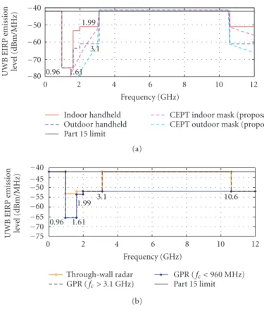
In March 2003, the European Commission gave a mandate [9] to the Eu-ropean standardization organizations, with the purpose of establishing a set of harmonized standards covering UWB applications. ETSI in turn established Task Group ERM TG31A to develop a set of harmonized standards for short-range devices using UWB technology by December 2004, following the completion of spectrum compatibility studies by CEPT. The output of this group has been de-layed. The standardization working groups for UWB include ERM/TG31A cov-ering generic UWB, and ERM/TG31B which covers UWB for automotive appli-cations at higher bands. These groups have developed two technical reports on communication and on radio location UWB applications, respectively. In the re-lated report [10] a preliminary slope mask is presented that allows UWB commu-nication systems to operate. This mask referred to inFigure 1.1as the provisional CEPT/ETSI mask is supported by the UWB industry within ETSI as the starting point for studies by CEPT. ETSI should further develop two standards on commu-nication and on radio location UWB applications.
0 2 4 6 8 10 12 Frequency (GHz)
0.96 1.61
1.99
3.1
−80
−70
−60
−50
−40
UWB
EIRP
emission
le
ve
l
(dBm/MHz)
Indoor handheld Outdoor handheld Part 15 limit
CEPT indoor mask (proposal) CEPT outdoor mask (proposal)
(a)
0 2 4 6 8 10 12
Frequency (GHz)
0.96 1.61
1.99 3.1 10.6
−75
−70
−65
−60
−55
−50
−45
−40
UWB
EIRP
emission
le
ve
l
(dBm/MHz)
Through-wall radar
GPR (fc>3.1 GHz)
GPR (fc<960 MHz)
Part 15 limit (b)
Figure1.1. UWB radiation mask defined by FCC and one early CEPT proposal.
The CEPT has already undertaken a number of compatibility studies which indicate that limits for emissions from UWB devices for communication appli-cations would need to be lower than the FCC limits in order to avoid harmful interference to some of the radio communication applications in CEPT countries. It is generally expected that ETSI/CEPT will follow some of the FCC’s recommen-dations but will not necessarily directly adopt the FCC’s regulations, now out of date!
Figure 1.1shows an early proposal for CEPT/ETSI mask limits as well as the agreed FCC masks. Figure 1.1(a) represents the masks for data communication applications for indoor and outdoor uses.Figure 1.1(b) gives the FCC radiation mask for radar and sensing applications. In all cases, the maximum average power spectral density follows the limit of FCC Part15 regulations [12]. Therefore, the limit will depend on compatibility studies results made by CEPT/TG3.
1.3.3. UWB regulation within ITU
implications of compatibility with radio communication services. The mandate of TG 1/8 is focused on the study of
(i) compatibility between UWB devices and radio communication services (Question ITU-R 227/1);
(ii) spectrum management framework related to the introduction of UWB devices (Question ITU-R 226/1);
(iii) appropriate measurement techniques for UWB devices.
TG1-8 is to complete its work in 2005 and will present to SG1 four new recommendations on UWB characteristics, UWB compatibility with other radio services, UWB spectrum management framework, and UWB measurement tech-niques, respectively.
1.3.4. UWB standardization in the IEEE
1.3.4.1. IEEE 802.15.3a
The IEEE established the 802.15.3a Study Group to define a new physical layer con-cept for short-range, high-data-rate applications. This alternative physical (ALT PHY) layer is intended to serve the needs of groups wishing to deploy high-data-rate applications. With a minimum data high-data-rate of 110 Mbps at 10 m, this study group intends to develop a standard to address such applications as video or multimedia links, or cable replacement. Whilst not specifically intended to be an UWB stan-dards group, the technical requirements lend themselves very much to the use of UWB technology. The study group has been the focus of significant attention re-cently as the debate over competing UWB physical layer technologies has raged. The work of the study group also includes analyzing the radio channel model pro-posal to be used in the UWB system evaluation.
The purpose of the study group is to provide a higher-speed physical layer (PHY) candidate for the existing, approved 802.15.3 medium access standard. The targeted applications are those which involve imaging and multimedia [14]. The main desired characteristics of the alternative PHY are
(i) coexistence with all existing IEEE 802 physical layer standards; (ii) target data rate in excess of 100 Mbps for consumer applications; (iii) robust multipath performance;
(iv) location awareness;
(v) use of additional unlicensed spectrum for high-rate WPANs (wireless personal area network).
1.3.4.2. IEEE 802.15.4
One option examined by the working group is utilizing UWB technology at the air interface. The study group addresses new applications which require not only moderate data throughput, but also require long battery life such as low-rate wireless personal area networks, sensors, and small networks.
1.3.5. The multiband OFDM alliance (MBOA)
The MBOA is an alliance of industry and academic partners which aims to develop physical layer and medium access layer technologies for UWB based on OFDM techniques [15]. The stated mission of the MBOA is to develop the best overall solution for UWB-based products in compliance with worldwide regulatory re-quirements as well as to ensure coexistence with current and future spectrum users [15].
In practice, the MBOA is formed in response to the impasse which existed in the IEEE 802.15.3a standardization attempt. The MBOA is still heavily involved in promoting its particular standard within the IEEE, but is moving to develop product for the market irrespective of the position of the IEEE standardization process.
1.4. Applications of UWB
Even with the significant power restrictions, UWB holds enormous potential for wireless ad-hoc and peer-to-peer networks. One of the major potential advantages in impulse-radio-based systems is the ability to trade data rate for link distance by simply using more or less concatenated pulses to define a bit. Without dramatically changing the air interface, the data rate can be changed by orders of magnitude depending on the system requirements. This means however that high-data-rate (HDR) and low-data-rate (LDR) devices will need to coexist. The narrow time-domain pulse also means that UWB offers the possibility for very high positioning accuracy. However, each device in the network must be “heard” by a number of other devices in order to generate a position from a delay or signal angle-of-arrival estimate. These potential benefits, coupled with the fact that an individual low-power UWB pulse is difficult to detect, offer some significant challenges for the medium access (MAC) design.
Figure 1.2shows the area of application for UWB with respect to existing and future networks. The low-power restricts UWB to very short-range high-data ap-plications, or very low data rates for moderate-range applications. The power re-strictions on transmission effectively prohibit UWB from most outdoor applica-tions. The increasing trend of users to combine both cellular and ad hoc technolo-gies (e.g., 802.11b WLAN and 2G cellular) is a strong indicator for the inclusion of high-speed short-range wireless in a comprehensive picture of future wireless networks.
Mo
b
il
it
y Out
d
oor
In
d
o
o
r
Stationary desktop
Walk Stationary
Walk Vehicle
2G
ce
llular 3G cellular
Wide-area network (WAN) -Large coverage
-High cost Personal area network (PAN)
-Connectivity -Cable replacement -Low cost
Local area network access -Hot speed
-High speed -Moderate cost
4G
HiperLAN/2
0.1 1 10 100
Mbps User bit rates
Figure1.2. Role of UWB in future systems.
have very low complexity and very low cost. The expected proliferation of low-cost UWB devices means that solutions must be devised for devices to coexist or preferably interoperate with many different types of UWB devices with different capabilities. The complexity limitations of LDR devices may mean that very simple solutions are required. HDR devices, which are expected to have higher complex-ity, may have much more sophisticated solutions.
Figure 1.3shows applications for UWB as perceived by members of the Eu-ropean Union project PULSERS [16]. These scenarios cover wireless local area networks (WLANs), wireless personal area networks (WPANs), sensor networks, and short-range peer-to-peer networks.
1.5. Impulse radio schemes
1.5.1. Impulse radio UWB
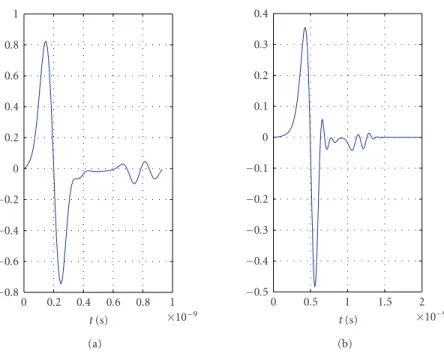
Time-modulated ultra-wideband (TM-UWB) communication is based on discon-tinuous emission of very short pulses or pulsed waveforms (monocycles), for ex-ample, one of those presented inFigure 1.4. Impulse-radio-based UWB has much in common with spread-spectrum systems. A major difference however is that the spread-spectrum “chip” is replaced by a discontinuous UWB “pulse” or monocy-cle transmission. The UWB pulse employed determines the bandwidth occupied by the signal.
Each pulse has the ultra-wide spectrum in the frequency domain (as presented inFigure 1.5). This type of transmission does not require the use of additional carrier modulation as the pulse will propagate well in the radio channel. The tech-nique is therefore a baseband signaling techtech-nique. This radio concept is referred as impulse radio (IR).
Deskt o p co m p u te r Lapt o p co m p u te r Dig ital camer a A u dio TV DV D Camc or der M o nit or PD A Gat ewa y
−1 −0.5 0 0.5 1 Time (ns)
−1
−0.8
−0.6
−0.4
−0.2 0
0.2
0.4
0.6
0.8
1
N
o
rm
aliz
ed
amplitude
Tp=0.25 ns
Tp=0.5 ns
Tp=0.75 ns
Tp=1 ns
Tp=2 ns
Figure1.4. Gaussian monocycle in time domain.
The UWB pulse waveform can be any function which satisfies the spectral mask regulatory requirements. Common pulse shapes used in theoretical studies include Gaussian, Laplacian, Rayleigh, or Hermitean pulses. In practical systems, exact pulse shapes are extremely difficult to generate due to antenna and radio fre-quency matching problems. Only coarse approximations of the theoretical wave-forms are available in practice.
Data modulation is typically based on simple modulation schemes such as pulse position modulation (PPM) and/or pulse amplitude modulation (PAM) [17]. A commonly proposed UWB receiver is a homodyne cross-correlator, that is, based on the architecture that utilizes a direct RF-to-baseband conversion. In-termediate frequency conversion is not needed, which makes the implementation simpler than in conventional (super-)heterodyne systems.
Unlike spread-spectrum systems, the pulse (chip) does not necessarily occupy the entire chip period. This means that the duty cycle can be extremely low. The receiver is only required to “listen” to the channel for a small fraction of the period between pulses. The impact of any continuous source of interference is therefore reduced so that it is only relevant when the receiver is attempting to detect a pulse. This leads to processing gain in the sense of a spread-spectrum system’s ability to reduce the impact of interference.
The nominal centre frequency and the bandwidth of the monocycle (see
Figure 1.5) depends on the monocycle’s width. The−3 dB bandwidth is approxi-mately 116% of the monocycles nominal centre frequency f0=1/τp[6].
Consid-ering an example monocycle duration of 0.75 nanosecond (as shown inFigure 1.4), the nominal centre frequency is 1.33 GHz and the half-power bandwidth is 1.55 GHz. The spectrum of a Gaussian monocycle is asymmetrical, as seen in
0 0.5 1 1.5 2 2.5 3 3.5 4 Frequency (GHZ)
0
0.2
0.4
0.6
0.8
1
PSD
Tp=0.25 ns
Tp=0.5 ns
Tp=0.75 ns
Tp=1 ns
Tp=2 ns
Figure1.5.Gaussian monocycle in frequency domain and spectra of the Gaussian monocycle.
Modulation
Time base Code generator
Variable delay Pulse generator Impulse radio transmitter
Time base Code generator
Variable delay Cross-generator
LPF
DSP
BPF
Modulation output Impulse radio receiver
Figure1.6.Block diagram of the TH-PPM UWB impulse radio concept by Time Domain Corpora-tion.
Figure 1.6presents a block diagram of a time-hopping UWB impulse radio concept that utilizes pulse position modulation (concept by Time Domain Corpo-ration, USA).
1.5.2. Fast stepped frequency chirps
f1f2 fn f
· · ·
C(n)
C(2)
C(1)
. .
. cos(2π fnt)
cos(2π f2t)
cos(2π f1t)
Σ
cos(2π fnt)
cos(2π f2t)
cos(2π f1t) g1
g2
gn ... LPF LPF LPF
Σ
Figure1.7. Block diagram and spectrum for multicarrier CDMA system.
radar applications. It is possible to generate a wideband transmission by sweep-ing the transmitter’s oscillator in the frequency domain. A bandwidth of several hundred MHz can be achieved with∼10 nanosecond sweep time [18]. Wider bandwidths can be achieved using this technique, for example, ground penetrat-ing radar (GPR) systems with 50–1200 MHz bandwidth have been documented in [19].
GPR systems based on UWB technology are suitable for object detection in, for example, landmine sweeping and avalanche rescue operations, because of the good signal penetration ability and fine spatial resolution.
1.6. Multicarrier schemes
Another approach to producing an UWB signal is to extend the techniques utilized for direct-sequence spread-spectrum or code-division multiple-access (CDMA) schemes that are used for third generation mobile systems. Wideband CDMA sys-tems with optional multicarrier (MC) techniques can be used to fill the available spectral mask.
There are three main techniques to generate an SS-MC transmission; multi-carrier CDMA, multimulti-carrier DS-CDMA, and multitone (MT) CDMA [20]. Each of these techniques relies on, and benefits from, the properties of conventional spread-spectrum signals. However, multicarrier systems are reasonably complex to implement. In particular, multicarrier systems require several mixers or digital fast Fourier transform (FFT) techniques to place the different signal components in the required bands.
Figure 1.7shows a block diagram for an MC-CDMA system. The original data stream is spread over the different subcarriersfiwith each chip of pseudo-random
(PR) codeCi. The spectrum spreading is done in the frequency domain [20]. The
signal is despread at the receiver using corresponding chipsgiof the spreading
codeC. In UWB applications, the individual modulated carrier needs to fulfil the 500 MHz bandwidth requirements.
Figure 1.8shows a block diagram for a multicarrier DS-CDMA system. This method involves spreading the original data in the time domain after serial-to-parallel conversion of the data stream [20]. The system needs to obtain the 500
Serial-to-parallel converter
f1f2 f fn
· · ·
C(t)...
C(t)
C(t)
cos(2π fnt)
cos(2π f2t)
cos(2π f1t)
Σ
cos(2π fnt)
cos(2π f2t)
cos(2π f1t) C(t)
C(t)
C(t)...
LPF LPF LPF
Parallel-to-serial converter
Figure1.8.Block diagram and spectrum for multicarrier DS-CDMA system.
Serial-to-parallel converter
f1f2fn
f Cn ...
C2
C1
cos(2π fnt)
cos(2π f2t)
cos(2π f1t)
Σ cos(2π f
nt)
cos(2π f2t)
cos(2π f1t)
. .
. RAKE
combinern
RAKE combiner 2
RAKE combiner 1
Parallel-to-serial converter
Figure1.9. Block diagram and spectrum for multitone CDMA system.
Figure 1.9shows the block diagram of a multitone-CDMA system. The band-width of an MT-CDMA system is smaller than in the previous multicarrier sys-tems because of the small subcarrier spacing. This kind of multicarrier approach is the closest to the original UWB concept. However, it causes the highest self-interference due to the overlapping spectra.
Multicarrier technology is currently used in high-data-rate applications, for example, in WLAN systems such as Hiperlan2, digital audio or video broadcasting (DAB and DVB, resp.) and in asymmetric digital subscriber line (ADSL).
The advantage of multicarrier technologies over single carrier systems is that the data rate in each subcarrier is lower than for single carrier systems. This eases synchronization with the spreading sequence at the receiver, and helps to avoid in-tersymbol interference (ISI). The disadvantage is the increased complexity of the receiver requiring either multiple mixing stages or fast Fourier transform process-ing. MC-CDMA schemes spread the signal in the frequency domain. The signal consists of overlapping, relatively narrow carriers which fill the available UWB signal spectrum. MC-DS-CDMA and MT-CDMA schemes apply spreading in the time domain. MT-CDMA has a similar bandwidth to a basic DS-CDMA scheme [20] with relatively small separation of the tones used (f1tofninFigure 1.9).
Con-sequently, the spreading factor employed for MT-CDMA schemes are much higher than for the MC schemes. The increased spreading factor increases the processing speed required at the receiver.
3 4 5 6 7 8 9 10 11
×109
Frequency
−10
−9
−8
−7
−6
−5
−4
−3
−2
−1 0 1
P
o
w
er
spect
ru
m
m
ag
nitude
(dB)
Figure1.10.Multiband frequency plan and spectral plan—Group A.
for extremely fast digital signal processing which may be impractical. Issues such as synchronization will also be a significant challenge.
1.6.1. Multiband UWB
A recent proposal within the IEEE 802.15.3 Working Group for UWB signals [14] utilizes overlapping groups of UWB signals which each has a bandwidth of approx-imately 500 MHz. Whilst not currently the leading proposal, this technique offers an interesting insight into the potential use of the very large spectrum available. This so-called multiband UWB ensures adherence to the FCC minimum band-width requirements and allows efficient utilization of the available spectrum.
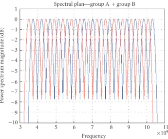
Figure 1.10 shows the spectrum plan for the first group of UWB signals (Group “A”). The subbands are spaced 470 MHz apart, and any number of 500 MHz signals may be utilized. This allows for flexible coexistence with existing communications systems (such as WLAN systems). Each subband is generated by a pulse with 10 dB bandwidth of∼520 MHz.Figure 1.11shows the second group of UWB signals (Group “B”) which overlaps the first group of UWB signals by 235 MHz. This potentially enhances the system’s flexibility with respect to coexis-tence, interference mitigation, and multiple access.
Each group of UWB signals is divided into lower sets (subbands 1–8) and upper sets (subbands 9–15). Only 7 subbands are used in the lower set, which means that one subband can be avoided for coexistence. The upper set is used in conjunction with the lower set to increase the bit rate.
1.6.2. Multiband OFDM
3 4 5 6 7 8 9 10 11
×109
Frequency
Spectral plan—group A + group B
−10
−9
−8
−7
−6
−5
−4
−3
−2
−1 0 1
P
o
w
er
spect
ru
m
m
ag
nitude
(dB)
Figure1.11.Multiband frequency plan and spectral plan of two overlapping frequency groups— Group A and Group B.
3168 MHz
3696 MHz
4224 MHz
4452. . . MHz Frequency Channel 1 Channel 2 Channel 3
Figure1.12. MBOA channel allocation scheme.
utilize OFDM techniques to produce a signal (channel) which is approximately 528 MHz wide. The signal structure is shown inFigure 1.12. The OFDM signal can be produced using standard FFT techniques [21].
1.7. Conclusions
signal also support location and tracking capabilities of UWB much more readily than in existing narrowerband technologies.
The severe restrictions on transmit power, allowing less than 0.5 mW maxi-mum power over the 7.5 GHz band in the FCC emission mask, have substantially limited the range of applications of UWB to short-distance high-data-rate, or low-data-rate, longer-distance applications. The great potential of UWB is to allow flexible transition between these two extremes without the need for substantial modifications to the transceiver. On the other hand, UWB technology emission masks outside the USA are still under discussion pending the outcome of compat-ibility studies with other radio services.
Whilst UWB is still the subject of significant debate, there is no doubt that the technology is capable of achieving very high data rates and is a viable alternative to existing technology for WPAN; short-range, high-data-rate communications; multimedia applications, and cable replacement. Much of the current debate cen-ters around which PHY layer(s) to adopt, development of a standard, and issues of coexistence and interference with other radio services.
At the time of writing, no standard exists for a MAC which has been specifi-cally developed for UWB which will support all of the unique advantages of UWB. The potential of UWB systems to offer flexible data rates, support coexistence, en-able large numbers of users and positioning services are critically dependent on the capabilities of the MAC.
Research is ongoing in industry and academic consortia including the IEEE, MBOA, and in European Union Projects such as PULSERS [22]. There is work ongoing in standardization bodies to adapt, optimize, and enhance existing MACs for use over UWB. Part of the reason for the slow progress in developing a flexible, comprehensive MAC specifically for UWB is due to the inherent complications of using a physical layer signal which is difficult to detect and difficult to synchronize for intended users. Efforts have been made to develop MACs which allow efficient operation for large numbers of devices. However, this work is still at an early stage.
Acknowledgments
The author would like to thank colleagues from CWC for input to this chapter. In particular, thanks to Matti H¨am¨al¨ainen and Jari Iinatti. The author would also like to thank colleagues from the Wireless World Research Forum (WWRF) Work-ing Group (Short Range Communications) for their input related to the regula-tory status section. In particular,thanks to Fr´ed´eric Lallemand and Guy Salingue. Thanks also to Therese Oppermann for careful proofreading.
Bibliography
[1] C. L. Bennett and G. F. Ross, “Time-domain electromagnetics and its applications,”Proceedings
of IEEE, vol. 66, no. 3, pp. 299–318, 1978.
[2] H. F. Harmuth,Nonsinusoidal Waves for Radar and Radio Communication, Academic Press, New
[3] FCC press release, Febrauary 2002,http://www.fcc.gov/Bureaus/Engineering Technology/News Releases/2002/nret0203.html.
[4] Federal Communications Commission (FCC), “First Report and Order in The Matter of Re-vision of Part 15 of the Commission’s Rules Regarding Ultrawideband Transmission Systems,” ET-Docket 98-153, FCC 02-48, released April 2002.
[5] J. D. Taylor, Ed.,Introduction to UWB Radar Systems, CRC Press, Boca Raton, Fla, USA, 1995.
[6] Time Domain Corporation, “Comments of Time Domain Corporation, Docket 98-154. In the Matter of Revision of Part 15 of the FCC’s Rules Regarding Ultra wide-band Transmission Sys-tems,” 1998.
[7] Federal Communications Commission (FCC), “FCC NOI: Rules Regarding UWB Transmission Systems,” ET Docket No. 98-153, September 1998.
[8] CEPT/ERC Recommendation 70-03, “Relating to the use of Short Range Devices (SRD)”. [9] EC Mandate M/329 to the European Standardisation Organisations, referenced in document
RSCOM03-07.
[10] ETSI TR 101 994-1 for communication and positioning applications.
[11] EC Mandate to CEPT, “Mandate to CEPT to harmonise radio spectrum use for Ultra-wideband Systems in the European Union,” referenced in document RSCOM03-40 rev. 3.
[12] Federal Communications Commission (FCC),http://www.fcc.gov, (Many standards documents
may be found on this site).
[13] I. Oppermann, F. Lallemand, and G. Salingue, “WWRF White Paper,” chapter 5, “UWB Spectrum Landing Zones,” 2004.
[14] http://www.ieee802.org/15/pub/.
[15] http://www.multibandofdm.org/about.html.
[16] “PULSERS White Paper,”WWRF Meeting, Eindhoven, The Netherlands, December 2002.
[17] J. T. Conroy, J. L. LoCicero, and D. R. Ucci, “Communication techniques using monopulse
wave-forms,” inProceedings of IEEE Military Communications Conference (MILCOM ’99), vol. 2, pp.
1181–1185, Atlantic City, NJ, USA, October–November 1999.
[18] G. F. Stickley, D. A. Noon, M. Chernlakov, and I. D. Longstaff, “Preliminary field results of an
ultra-wideband (10–620 MHz) stepped-frequency ground penetrating radar,” inProceedings of
IEEE International Geoscience and Remote Sensing (IGARSS ’97), vol. 3, pp. 1282–1284, Singapore, August 1997.
[19] L. Carin and L. B. Felsen, Eds.,Ultra-Wideband, Short-Pulse Electromagnetics 2, Conference
Pro-ceedings, Kluwer Academic/Plenum Press, New York, NY, USA, 1995, 605 pages.
[20] R. Prasad and S. Hara, “An overview of multi-carrier CDMA,” inProceedings of IEEE 4th
Inter-national Symposium on Spread Spectrum Techniques and Applications (ISSSTA ’96), vol. 1, pp. 107–114, Mainz, Germany, September 1996.
[21] MBOA White paper,http://www.multibandofdm.org/, September 2004.
[22] http://www.pulsers.net/main.shtml.
Ian Oppermann: Department of Electrical and Information Engineering, University of Oulu, FIN-90014, Finland
2
UWB propagation channels
Andreas F. Molisch, J¨urgen Kunisch, Robert Qiu,
Dajana Cassioli, Michael Buehrer,
Marcus Pendergrass, Istv´an Z. Kov´acs,
Gert F. Pedersen, Patrick C. F. Eggers,
Sumit Roy, and Iyappan Ramachandran
2.1. Introduction
2.1.1. General aspects of channel modeling
As with any other communications system, it is thechannelthat determines the ul-timate (information-theoretic) performance limits, as well as the practical perfor-mance limits of various transmission schemes and receiver algorithms. For UWB systems, this channel is the ultra-wideband propagation channel. Understanding this channel is thus a vital prerequisite for designing, testing, and comparing UWB systems. Just like UWB communications itself, channel modeling for UWB is a rel-atively new area. And just as the interest for UWB systems has intensified in the last years, so has the importance of modeling the UWB propagation channels. In this chapter, we will give a comprehensive overview of the state of the art in this exciting area.
Quite generally, wireless channel modeling is done for two different purposes. (i) Deterministic channel modeling tries to predict the behavior of a wire-less channel in a specific environment. If a complete description of the geometry, as well as of the electromagnetic properties of the materials, of the surrounding of transmitter and receiver is given,1then Maxwell’s equations can be solved exactly, and the channel impulse response (or an equivalent quantity) can be predicted. This approach, which had long been deemed too complicated, has become popular in the last 15 years. Ray tracing and other high-frequency approximations, as well as the ad-vent of more powerful computers, have made it possible to perform the required computations within reasonable time.
(ii) Stochastic channel models try to model the “typical” or “canonical” properties of a wireless channel, without relating those properties to a specific location. As the most simple example, the probability density
1The size of the “surroundings” depends on the environment, as well as on the desired dynamic
function of the (narrowband) amplitude of the received signal is mod-eled as Rayleigh-distributed within a small area (part of a room). In con-trast, a deterministic model would try to predict the exact amplitude values at each location in that part of a room.
There is an enormous amount of literature fornarrowbandwireless channels; for textbooks and overview articles, see [1–10]. However, those models cannot be easily generalized to UWB channels, due to some important basic differences in the propagation processes and the resulting models. Some of these differences are the following.
(i) Each multipath component (MPC) can lead to delay dispersion by itself, due to the frequency-selective nature of reflection and diffraction coef-ficients. This effect is especially important for systems with largerelative bandwidth.
(ii) The signals are received with excellent delay resolution. Therefore, it of-ten happens that only a few multipath components make up one resolv-ableMPC, and the amplitude statistics of such a resolvable MPC is not complex Gaussian anymore. Similarly, there is an appreciable probabil-ity that areas of “no energy” can exist, that is, (resolvable) delay intervals during which no significant amount of energy is arriving at the receiver. These issues are mostly important for systems with largeabsolute band-width.
By definition, a UWB channel is a more general description of nature than a narrowband channel: it is always possible to obtain a narrowband channel from a UWB channel by just filtering the UWB channel. Extrapolation from narrowband to UWB is tempting, as it allows the reuse of existing measurements. However, it is extremely dangerous, and has to be backed up by measurement data. Every aspect of narrowband channel modeling has to be questioned before it can be accepted for UWB modeling!
2.1.2. Regulatory and application-specific aspects
The frequency range of UWB systems is limited by transceiver design issues (tran-sit frequency of semiconductor components, antenna bandwidth, etc.), as well as rulings of the frequency regulators. Channel models should be mindful of those limitations: after all, the main purpose of channel models is the design and testing of UWB systems, and as the systems face practical and legal limitations, there is no need to be overly general in the models either.
Up to now, only the regulator in the USA has issued rulings that allow the use of UWB.2The report and order of the FCC from 2002 [11] allows unlicensed operation of UWB communications devices in indoor environments, mainly in the frequency range between 3.1 and 10.6 GHz. The admissible power spectral density is−41.3 dBm/MHz, and considerably lower outside that band (the exact
2Singapore has recently established a “UWB-friendly zone,” and other countries are expected to
101
100
Frequency (GHz)
−75
−70
−65
−60
−55
−50
−45
−40
UWB
EIRP
emission
le
ve
l
(dBm)
Indoor limit Part 15 limit
Figure2.1. FCC mask for indoor communications.
mask is shown inFigure 2.1). Communications is also allowed at frequencies be-low 960 MHz. There are certain restrictions in the applications, as well as in peak-to-average ratios; however, those have no impact on the channel modeling. It is important that outdoor devices must not be fixed, or have a connection to power mains-only peer-to-peer communications of portable devices is allowed. These re-strictions limit the frequency range in which the channel model needs to be valid, as well as the possible distance between transmitter and receiver.
The envisioned applications give us guidelines about what propagation envi-ronments are of greatest interest for UWB applications. A main point of emphasis is high-data-rate personal area networks (PANs). A typical application there is the transmission of digital TV signals via a wireless link. It follows that such high data rates, in conjunction with the limits on the power spectral density, can be per-formed only over short distances (on the order of 10 m), and are of interest mostly for residential and office environments. Another application of interest is sensor networks. As the data rates are much lower in this context, longer ranges are possi-ble. Furthermore, sensor networks can be of great interest in factory environments, where “indoor” distances can be larger, and the abundance of metallic reflectors can lead to quite different propagation conditions.
2.1.3. Synopsis of the chapter
A first step in understanding UWB propagation has to be measurements of UWB channels. For this task, we have two different types of measurement techniques at our disposal: frequency-domain measurements, employing a vector network an-alyzer, give the transfer function of the channel; alternatively, the channel can be excited with a short pulse, and a time-domain measurement of the received signal returns the convolution of the pulse with the channel impulse response. In either of those cases, the impact of the antenna on the measurement results is crucial. In fact, it is much more important than in the narrowband case, because the an-tenna characteristics vary significantly with the frequency, and exhibit a different response in different directions.Section 2.2byKunischgives a detailed mathemat-ical model for these effects, and suggests a procedure for the deconvolution of the antenna effects.
As mentioned above, a crucial property of UWB channels is the fact that each multipath component can show delay dispersion by itself. That means that a short pulse that, for example, undergoes only a single diffraction will arrive at the receiver with a larger support (extent in the delay domain) compared to the originally transmitted pulse. The reason for this is that the diffraction coef-ficient is frequency-dependent.Qiudescribes inSection 2.3the mathematics of these processes. Exact and approximate formulations, based on the uniform the-ory of diffraction, allow a modification of the classical Turin model, so that the impulse response in a multipath environment is now the sum ofdistorted, scaled, and delayed pulses. This has important implications for the design of correlation receivers, which are also addressed in this section. From a more experimental point of view,Molisch and Buehrer discuss the impact of frequency-selective reflection coefficients inSection 2.5.5. The results from these sections can be combined with classical ray tracing approaches, resulting in a deterministic channel prediction and modeling method.
short-range communications in indoor office environments. More general chan-nel models are currently under development within the IEEE 802.15.4a group, but not yet finalized at the time of this writing, and therefore not further treated here.
All of the above considerations are for a channel without human presence— measurement campaigns (as well as the models based on them) usually try to avoid the influence of human bodies on the measurement results as much as possible. This assumption might be realistic, for example, for an antenna mounted on a DVD-player, which establishes a video link. However, it becomes untenable for “body-area network,” where the antenna is placed directly on a body of a user— antenna and body become inseparable. This case requires new measurement tech-niques, and also new channel models.Kovacs, Pedersen, and Eggersdescribe mea-surement setups that are especially suitable for this situation (seeSection 2.7). A main difficulty is the impact of cables between antenna and network analyzer (or oscilloscope); this problem is solved by using RF-over-fiber.
Finally,Section 2.8byRoydeals with the topic of channel estimation. While it is clearly similar to the problem of measuring channels, there are also important conceptual differences. Channel estimation always must be viewed in light of the system it is being performed for, while channel measurement and modeling tries to remain as system-independent as possible. Also, channel estimation has to use a signaling structure that is similar to the signaling (modulation) of the payload data—cost considerations do not allow the building of an additional transceiver with a different structure, just to obtain channel estimates. Due to these reasons, the estimation techniques for OFDM-based UWB systems on one hand and for impulse-radio and direct-sequence CDMA systems on the other hand are quite different. Both are treated inSection 2.8.
2.2. Measurement techniques
2.2.1. Introduction
In this section, we will give a review of the measurement techniques that can be used to characterize UWB radio channels and discuss some of their properties. We give analytical expressions for the transfer functions of some elementary UWB radio channels. A particular problem for UWB measurements is the removal of an-tenna influences from radio channel measurements (de-embedding), which needs to account for specific UWB properties of antennas. For that purpose, charac-teristic functions are defined that describe the UWB transmission and reception properties of an antenna. A general relationship that exists for these functions is derived, to finally arrive at a formulation of the de-embedding problem suited for ultra-wide bandwidths.
What is a radio channel, in the first place? In this section, we will consider any arrangement of two or more antennas, of which at least two are coupled by far field radiation, a radio channel. If the total number of connectors of all antennas is N, the corresponding radio channel can be viewed simply as anN-port. This def-inition covers the cases of SISO, SIMO, and MIMO channels. This defdef-inition also includes the antennas into the channel, and consequently changing the antenna characteristic may change the properties of the channel as well. Therefore, a radio channel can be viewed as the result of combining “antennas and propagation.”
The inclusion of antennas into the radio channel definition follows practical considerations regarding system design to some extent: all radio systems (includ-ing those for measur(includ-ing radio channels) need to use some form of antenna, and in many cases the intended application imposes constraints on the antennas that can be used for a particular system—for example, handset antenna designers have to cope with strong restrictions related to the form factor of the handset.
This poses the problem that results obtained for a particular radio channel using a certain measurement setup in the strict sense only apply to channels in-corporating the antennas used during that measurement. To use such results for systems with different antennas, some further steps are required. Consequently, it is frequently required to consider a channel concept that is independent of the em-ployed antennas. We will refer to this type of channel as a “propagation channel”; its ports are not related to feed lines of antennas, rather they are directly related to the propagating fields.
Another approach employs antennas that are “neutral” in the sense that radio channel measurements with these antennas do not disturb the characteristics of the underlying propagation channel significantly—so these may be recovered eas-ily. Isotropic antennas would make a good choice for this type of measurement; however, isotropic antennas exist only as a theoretical device. A frequent com-promise is the use of omnidirectional antennas. Using this type of antenna at the transmitter, for example, allows to determine “unbiased” azimuth-power spectra at the receiver in the horizontal plane.
All of the above considerations are not specific to UWB radio channel mea-surements. However, what is specific to UWB conditions is the particular signif-icance of frequency dependence. While it is often feasible to assume the radia-tion pattern to be constant over the band for (non-ultra-) wideband systems (e.g., WCDMA with a fractional bandwidth of approximately 1/400), the frequency de-pendence of antennas must not be neglected in UWB applications. Furthermore, the UWB radio channel may exhibit certain frequency dependencies even for “fre-quency-independent” antennas, which is due to the fact that an antenna cannot be frequency-independent in both transmission and reception; which in turn is caused by constraints imposed by reciprocity. Before we look into this and the im-plications of these frequency dependencies for the formulation of the de-embed-ding problem, we first give a short review of some basic measurement approaches that can be used for UWB radio channel measurements.
2.2.2. Basic measurement approaches
An important assumption for the characterization of mobile radio channels is lin-earity. An exhaustive treatment of time-variant linear systems has been given by Bello [12,13] in terms of various system and correlation functions that are related by Fourier transforms. The basic measurement approaches can be directly related to several of these system functions. For example, following [12], the responsew(t) of a time-variant linear system to a stimulusz(t) can be written as
w(t)=
z(t−ξ)g(t,ξ)dξ=
z(t−ξ)h(t−ξ,ξ)dξ, (2.1)
performed inside the DSO, as this may affect the amplitude statistics of the signal finally delivered by the DSO.
In a similar fashion, for an input signalZ(f) that is localized in frequency domain, for example,Z(f)=δ(f −f0),3the input-output relationships
W(f)=
Z(f −ν)H(f,ν)dν=
Z(f −ν)G(f −ν,ν)dν (2.2)
allow to determineW(f)=H(f,f −f0)=G(f0,f −f0), whereHandGare the input Doppler-spread function and output Doppler-spread function. These equa-tions are useful for channels that are discrete in Doppler domain, that is, channels with quasiperiodic time variance, with only a few fundamental Doppler frequen-cies. For example, consider a single ray that passes through a fluorescent tube: the oscillating plasma inside the tube introduces a Doppler shift of multiples of twice the local power line frequency. Using a tunable CW source as transmitter and a DSO as receiver, the Doppler behavior of this type of channel can be accurately characterized over ultra-widebands.
The time-variant transfer function
T(f,t)=
g(t,ξ) exp(−j2π f ξ)dξ (2.3)
and the associated input-output relationship
w(t)=
Z(f)T(f,t) exp(j2π f t)df (2.4)
are useful for “frequency-domain” measurements. ForZ(f)=δ(f −f0), we have
w(t)=Tf0,texpj2π f0t, (2.5)
and for slowly time-varying channels, that is,
T(f,t)≈Tf,t0 fort−t0< 1
f0, (2.6)
we get
w(t)≈Tf0,t0expj2π f0t, (2.7)
3Note that to obtain a real signalz(t)∈R,Z(f) has to exhibit complex conjugate symmetry with


![Figure 2.9. Mean and variance of the Nakagami m-factor as a function of the excess delay for a base- base-band (< 0.5 GHz) measurement (according to [79]).](https://thumb-us.123doks.com/thumbv2/123dok_us/8185890.2170110/89.702.203.503.102.417/figure-variance-nakagami-factor-function-excess-measurement-according.webp)