Determinism in GPU Programs
Real Time Applications on the NVIDIA Jetson TK1
Vance Miller
Senior Honors Thesis
Department
of
Computer Science
The University
of
North Carolina
at
Chapel Hill
April 27, 2016
Approved:
Thesis Advisor Date
Contents
1 Motivation 4
1.1 Computer Systems in Automobiles . . . 4
1.2 Advanced Driver Assistance Systems . . . 4
1.3 Costs . . . 5
1.4 Processing Sensory Input . . . 5
2 Definitions 6 2.1 Image Processing Scenario . . . 6
2.2 Real-Time System . . . 7
2.3 Automotive Real-Time System . . . 7
2.4 CUDA Programming Model . . . 8
2.5 NVIDIA Jetson TK1 . . . 8
2.6 GPU Limitations . . . 9
2.7 Zero Copy Memory . . . 10
3 Experiments 10 3.1 Experiment Design . . . 10
4 Results 12 4.1 Worst-Case Execution Time . . . 12
4.2 Matrix Multiplication Average and Worst Case . . . 13
4.3 Matrix Multiplication Copy Engine . . . 14
4.4 Matrix Multiplication Execution Engine . . . 15
4.5 Matrix Multiplication with Zero Copy . . . 16
5 Conclusions 17 Appendix A CUDA Locking and Synchronization Library 18 A.1 Evaluation of Locking Library . . . 18
Appendix B Source Code 20
Appendix C Acknowledgments 20
1
Motivation
The leading cause of automotive accidents is driver error [1]. Self-driving cars remove the driver from the equation and, if designed properly, make the roadways safer for everyone. Unfortunately, self-driving cars are still far from being commonplace. As more people become receptive to the idea of owning and being transported by autonomous vehicles, the pressures will increase for auto-motive manufacturers to innovate and build cars that are affordable and safe to drive. The challenge is building a system that is reliable and predictable enough to pass the stringent certification requirements that will regulate autonomous vehicle manufacturing in the future [11].
1.1
Computer Systems in Automobiles
In modern cars, there are tens to hundreds of computers in use at any given time [10]. Many of these computers perform simple tasks like controlling emis-sions or monitoring battery levels. The higher-level operations of a car have traditionally been handled by human drivers. The ultimate goal is to design and ensure that a computer system can drive a car as well as—or better than— a human driver.
Such a computer system is not readily available for our research purposes, so instead we focus our research on advanced driver assistance systems (ADAS). ADAS are the natural precursors to autonomous driving as the functions they perform make up important parts of a fully autonomous system.
1.2
Advanced Driver Assistance Systems
We see the beginnings of autonomous vehicle technology already available and on the road today in ADAS. These systems, illustrated in Figure 1, have applications in areas like forward collision detection, automatic braking, lane departure warning, and intelligent cruise control to name a few [3].
The high cost of ADAS is primarily driven by the cost of the sensor and com-puter hardware required to power them and has been prohibitive for widespread adoption; however, in some cases the safety benefits outweigh the costs and as of 2015 several U.S. automobile manufacturers have agreed to install automatic braking systems as standard equipment in all new vehicles [14].
Figure 1: Advanced driver assistance systems and sensors [13].
1.3
Costs
As driver assistance technologies become standard, economies of scale dictate that the systems will become more affordable. In order to further reduce the cost of ADAS, we turn to the hardware supporting the computation.
Processing data on graphics processing units (GPUs) rather than CPUs offers a large speedup for parallelizable operations [12]. In ADAS, raw camera input must be interpreted by a computer vision algorithm before the system can react to it. Processing a continuous stream of images from a camera at a high speed is a common use case for GPUs.
In comparison with Google’s self-driving car and other systems today that use LIDAR and specially designed hardware, off-the-shelf cameras and GPUs are significantly cheaper [15]. We are evaluating the NVIDIA Jetson TK1 as a potential GPU platform for use in an automotive setting. The Jetson is designed for embedded applications and sells for less than $200, making it an attractive candidate for use in a non-luxury car. We would like to determine how well a system built with commodity hardware such as the Jetson can handle the high workload necessary in an automotive setting.
1.4
Processing Sensory Input
Figure 2: Image from dashboard-mounted camera with results of the vehicle tracking algorithm superimposed [4].
algorithm running on the images captured by a dashboard-mounted camera. In this work, we focus specifically on processing input from car-mounted cameras.
2
Definitions
In the following sections we formalize the problem we are solving and define terms. Our goal is to quantify the image processing workloads the Jetson is capable of handling and determine if it is suitable for use in an automotive setting.
2.1
Image Processing Scenario
We evaluated a variety of computer vision algorithms that are applicable to automotive systems. In each use case a program takes input images from car-mounted cameras, runs the algorithm, returns a result, and repeats with a new frame. For each input frame the program’s output is used to help the car make a driving decision.
2.2
Real-Time System
The timing constraints we described in the image processing scenario above describe a real-time system. A real-time system has logical and temporal con-straints. A program in a real-time system must 1) produce a logically correct result and 2) complete computation by a designated time [9]. If either of these requirements is not met, the program fails.
In the conventional real-time system model, an executing program is called a task. A task becomes available for execution at its release time and can begin execution at any time after. The task must complete execution before itsdeadline. Tasks usually must run repeatedly so the amount of time between consecutive releases is the program’speriod. The amount of time a task requires to execute is its execution time. The execution time can vary across different releases of a task but all tasks require no more than theirworst-case execution time to complete. We define task utilization as the worst case execution time divided by the task period. If the worst-case execution time is larger than the period, the system isover utilized. We should not design a system that is over utilized as it could fail whenever a task executes beyond its deadline [9].
A real-time system has various scheduling algorithms for ensuring that tasks are released periodically and deadlines are met in an environment where many programs can be running at once. In Linux we have first-in first-out, round robin, and earliest-deadline-first scheduling algorithms available. In our exper-iments we only ran one task at a time, which led to no significant difference between scheduling classes. We do not consider the effect of real-time schedul-ing algorithms in this work.
In this research we focus on the the timing requirements of a real-time system by measuring how long computer vision algorithms take to complete computa-tion on the NVIDIA Jetson TK1. We would like to determine the worst-case execution time of various computer vision algorithms in order specify realistic periods between releases.
2.3
Automotive Real-Time System
An autonomous vehicle must be as good as or better than a human driver. The average reaction time of an alert human driver is 700ms [8]. Hence, each task in our system must have a runtime that is bounded above by 700ms. Often, the bound should be much lower, especially in safety-critical tasks that could prevent the loss of life, like pedestrian detection.
video frame rate available in typical video cameras.
It is difficult to predict how much time is required to execute a specific GPU task. We must assume that every task will take as long as its worst-case execution time. In this work, the worst-case execution time of a program is determined experimentally by measuring the program’s runtime on a variety of inputs and configurations. The largest runtime measured can be used as the worst-case execution time. If the worst-case execution time of the pedestrian detector is 100ms then the pedestrian detector can be run with a period no smaller than 100ms. In practice, real-time systems add an additional “buffer” to the worst-case execution time for additional assurance that the system has enough time to complete the task in the worst case.
If the average runtime of a task is significantly lower than its worst-case execution time then the system’s processing capacity can go unused. Hence, our objective is to reduce the worst-case execution time of programs as near to the average runtime as possible so that the system spends less time under-utilized.
2.4
CUDA Programming Model
CUDA is a GPU programming language designed by NVIDIA that has been used to implement many computer vision algorithms. CUDA programs all have the following general structure.
1. The CPU makes data available to the GPU.
2. The GPU performs the computation on the data.
3. The GPU makes the result available to the CPU.
The simplicity of the CUDA programming model provides an easy-to-use interface that allows programmers to use GPUs; however, we will later see that programmer design decisions about how data is handled can cause detrimental worst-case performance. The performance trade off is not apparent when the programmer is writing the CUDA code because the program is functionally correct either way. The effects of these choices on timing correctness are not apparent until after experimentation.
2.5
NVIDIA Jetson TK1
GPUs are capable of executing computer vision algorithms much faster than CPU-based equivalents [7]. We chose the NVIDIA Jetson TK1 as our target platform because it has a GPU and a CPU in one package, is affordable, designed for embedded applications like automotive systems, and has an active developer community.
memory, many more processing cores, and consume more power than integrated GPUs. The Jetson is unique in this area because it integrates the CPU and GPU on the same physical chip and shares memory between the two.
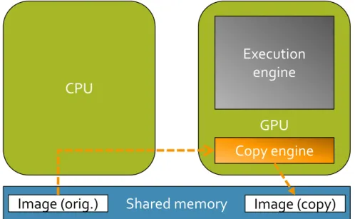
Figure 3 shows the architecture of the Jetson. The GPU consists of two major components: a copy engine and an execution engine. The copy engine is responsible for moving data to and from GPU-managed memory. The execution engine handles executing the GPU program, called akernel. In the Jetson, and other integrated systems, physical memory is shared between the CPU and the GPU. Using the shared memory improperly increases the worst-case runtime but it is possible to use it to our advantage, as we will see later in the experiments.
CPU
GPU
Execution
engine
Copy engine
Shared memory
Image (orig.)
Image (copy)
Figure 3: NVIDIA Jetson TK1 architecture. The Jetson integrates the CPU and GPU on the same physical chip and both share the same physical memory. The GPU consists of one copy engine and one execution engine. The copy engine moves data between CPU-managed memory and GPU-managed memory.
2.6
GPU Limitations
2.7
Zero Copy Memory
In CUDA programs, CPU memory and GPU memory are used as if they are physically separate, as in discrete GPUs, by default. When the CPU data is made available to the GPU, it is copied from CPU memory to GPU memory. On systems with integrated GPUs, such as the Jetson, the CPU and the GPU share the same physical memory so when data is copied from CPU memory to GPU memory, it moves from one region of memory to another in the same DRAM banks. On these systems, it is possible for the CPU and GPU to access the same regions of memory when CUDA programs are implemented with Zero Copy CUDA library functions.
Using Zero Copy can reduce the memory requirement of GPU programs by up to half because the CPU and the GPU do not need to maintain separate copies of the data. The CPU has access to the original data. Instead of making a copy of the original data, the GPU uses a pointer to the CPU’s copy for com-putation. We measure the impacts of caching and data movement by comparing the runtime of the default program implementation to the runtime of the Zero Copy implementation.
3
Experiments
Ideally, our GPU programs would have deterministic runtime for a given input size. Determinism allows us to measure the worst-case runtime experi-mentally and expect all future runs of the program to perform similarly. Our initial tests suggested that some configurations of GPU programs have high variability so we designed experiments that isolated the sources of variability in CUDA programs.
CPU-GPU interactions are limited to memory allocation, memory copies, and kernel execution. In our experiments, we measured the runtime of these in-dividual GPU operations for varied input sizes. Calls tocudaMalloc,cudaFree, and cudaMemcpy reference GPU memory and engage the GPU’s copy engine. Calls tocudaLaunch for kernels engage the GPU’s execution engine.
Shared memory between the CPU and the GPU is another source of un-predictability. When a CPU program accesses the shared DRAM banks at the same time as a GPU program one must wait for the other to complete its mem-ory operations before it can have access. We attempt to minimize these issues by running only one experimental process at a time. In addition, we minimize memory usage with Zero Copy memory and evaluate how Zero Copy memory performs compared to the default implementation.
3.1
Experiment Design
CUDA samples and was minimally modified to support timing measurements and Zero Copy memory.
4
Results
4.1
Worst-Case Execution Time
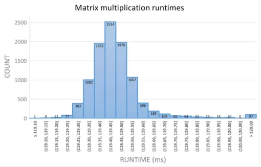
Initial observations show that off-the-shelf CUDA programs do not have deterministic performance. Figure 4 shows a histogram of measured runtime of the matrix multiply program for matrices containing 220 (32-bit) floating-point numbers. The median time required to execute the program was 119.4ms however there is a long right tail in the distribution that brings the average execution time up to 125.5ms. The maximum observed runtime was 1357ms, well beyond the right edge of the graph.
Figure 4: Histogram of matrix multiplication runtime for input size 220.
4.2
Matrix Multiplication Average and Worst Case
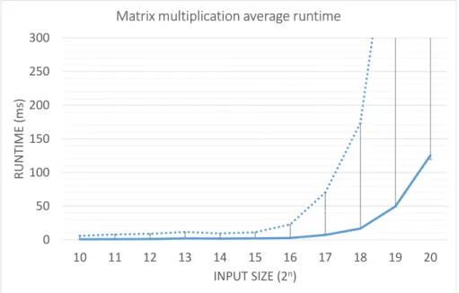
In Figure 5 we display the results of timing the matrix multiplication pro-gram across all input sizes. We varied the input size from 210 to 220 (32-bit) floating point numbers per matrix. A matrix with 210floats is a 32×32 matrix. A matrix with 220 floats is a 1024×1024 matrix.
The plot shows the average time in milliseconds across 10,000 iterations re-quired to make data available to the GPU, multiply the two matrices, and return the result to the CPU. As the size of the input to the program increases, the average task runtime, displayed as a solid line, increases as well. The observed worst-case execution time increases at a much faster rate and is displayed as error bars and as the dotted line. For example, with input size 218 the average task execution time is 15ms while the observed worst-case execution time is 170ms.
0 50 100 150 200 250 300
10 11 12 13 14 15 16 17 18 19 20
RU
NT
IM
E (
m
s)
INPUT SIZE (2n)
Matrix multiplication average runtime
Figure 5: Matrix multiplication average runtime per input size represented by solid line. Worst-case execution time shown in error bars and dotted line.
4.3
Matrix Multiplication Copy Engine
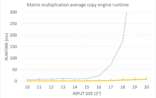
Figure 6 shows the time the matrix multiplication program spends using the GPU’s copy engine. The copy engine is used for memory copies. In our program the copy engine is used to copy the two input matrices to GPU memory and to copy the resulting matrix to CPU memory after it is constructed.
Memory copies make up a small portion of the task’s overall runtime. The worst-case runtime observed during this phase of computation (represented by the error bars) was low and did not appear to vary with input size. The worst-case runtime also does not approach the overall worst-worst-case runtime (dotted) as input size increases.
0 50 100 150 200 250 300
10 11 12 13 14 15 16 17 18 19 20
RU
NT
IM
E (
m
s)
INPUT SIZE (2n)
Matrix multiplication average copy engine runtime
4.4
Matrix Multiplication Execution Engine
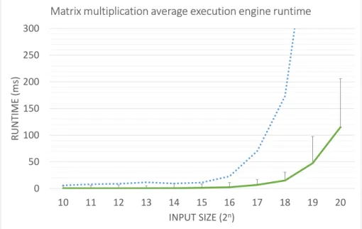
Figure 7 shows the time the matrix multiplication program spends using the execution engine. The execution engine is used for executing the GPU code. In this case the GPU code handles loading the matrix elements from GPU memory, performing arithmetic operations on the values, and storing the result in GPU memory.
The execution engine runtime accounts for most of the runtime of the entire task; however, there is still a significant gap between the worst-case execution engine runtime and the overall worst-case execution time. The worst-case exe-cution time is not explained by the exeexe-cution engine’s runtime alone.
0 50 100 150 200 250 300
10 11 12 13 14 15 16 17 18 19 20
RU
NT
IM
E (
m
s)
INPUT SIZE (2n)
Matrix multiplication average execution engine runtime
4.5
Matrix Multiplication with Zero Copy
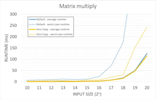
In order to isolate the impacts of the Jetson’s shared memory on overall program runtime, we reimplemented matrix multiplication with CUDA’s Zero Copy memory features. Figure 8 shows the results. We observed that using Zero Copy memory does not significantly reduce the average execution time. Since memory operations only accounted for a small amount of total runtime (Figure 6), this is expected.
More importantly, the worst-case execution time of the entire task is lower when implemented with Zero Copy compared to the default implementation. For example, the worst-case execution time for input size 218 dropped from 170ms originally to 30ms with Zero Copy.
0 50 100 150 200 250 300
10 11 12 13 14 15 16 17 18 19 20
RU
NT
IM
E (
m
s)
INPUT SIZE (2n)
Matrix multiply
Default - average runtime Default - worst case runtime Zero Copy - average runtime Zero Copy - worst case runtime
5
Conclusions
Our goal is to make GPU programs more predictable and to close the gap between worst-case execution time and average execution time. We found that the copy engine and the execution engine have unpredictability in their execution times but the most significant source of variation was in the communication and synchronization between the CPU and the GPU which did not involve either engine.
Programs implemented with Zero Copy memory have significantly lower worst-case execution time than the default implementation. Zero Copy reduces the number of memory operations a program performs and reduces its total memory requirements. Our findings show that Zero Copy on the Jetson has benefits for program predictability and average runtime.
Appendix A
CUDA Locking and Synchronization Library
When multiple GPU-using tasks run concurrently they should share the GPU fairly. Here, our notion of fairness depends on the task’s priority on the CPU. This means that if two concurrent tasks request access to the GPU at the same time, the high priority task should always receive access before the low priority task. Further, if a low priority task is using the GPU and a high priority task requests access, the GPU should preempt the low priority task and allow the high priority task to run instead. We prioritize tasks based on their safety criticality. For example, forward collision avoidance has a higher priority than lane departure warning.
Unfortunately, the GPU’s kernel scheduler does not schedule tasks according to their CPU priority. In addition, GPUs are non-preemptable resources so once a task begins it is not possible to cancel or pause it [7].
We have developed a mechanism to bypass the GPU’s kernel scheduler and impose priority on GPU operations. We accomplish this by intercepting all function calls a program makes to the CUDA library. The intercepted function calls use locking to ensure that only the task with the highest priority is allowed to access to the GPU at once. All other tasks wait for the task that holds the lock to finish before contending for the lock. Locking occurs on the CPU, so we avoid the GPU’s scheduler altogether.
Our interception library is modeled after GPUSync, a large body of code that achieves the same effects and much more. GPUSync was implemented by modifying theLitmusRT patch to the Linux kernel and consists of over 20,000
lines of code [7]. Our goal with designing the locking library was to build a lightweight version of GPUSync that could be usable in embedded systems that are significantly less powerful than the platforms GPUSync was originally intended for. Our locking protocol and interception library is implemented using standard Linux libraries and with only 554 lines of code. Further, our library has shown to be effective in making periodic tasks execute on the GPU in accordance with their CPU priorities.
A.1
Evaluation of Locking Library
We evaluated the effectiveness of our locking protocol by running multiple GPU programs concurrently using a simple framework for releasing tasks peri-odically. We counted the iterations each task was able to complete in 30 seconds. In these experiments we used vector addition and stereo disparity programs from the official NVIDIA CUDA samples.
A.1.1 Stereo Disparity
repeats these steps for thirty seconds. Figure 9 shows the effects of locking when four instances of stereo disparity are run concurrently.
−1 −2 −3 −4
0 1,000 2,000
Process priority
Av
erage
iterations
in
30
seconds
Stereo Disparity: Locks vs. no Locks with Varied Priorities
No locks Locks
Figure 9: Stereo disparity iteration count with no locks and varied priorities for four processes.
Average total throughput was higher when locks were disabled, however, as shown in Figure 9, this does not mean that processes executed in a manner proportional to their priority. With locks disabled, processes use the GPU without regard to CPU priority and block higher priority processes. With locks engaged, processes use the GPU according to their CPU priority.
A.1.2 Vector Addition
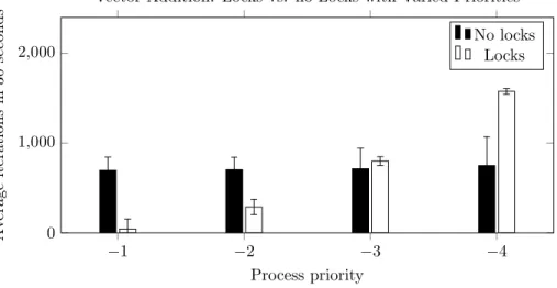
The vector addition sample program copies two 16 Mbyte vectors from the CPU to the GPU, performs 4 million single-precision floating point add opera-tions, and copies the resulting 16 Mbyte vector from the GPU to the CPU. The program repeats these steps for thirty seconds.
−1 −2 −3 −4 0
1,000 2,000
Process priority
Av
erage
iterations
in
30
seconds
Vector Addition: Locks vs. no Locks with Varied Priorities
No locks Locks
Figure 10: Vector addition iteration count with no locks and varied priorities for four processes.
Appendix B
Source Code
• Locking library and sample programs.
http://github.com/vancemiller/gpu-sync
• Periodic task framework and worst-case execution time benchmarking.
http://github.com/vancemiller/PeriodicTaskReleaser.
Appendix C
Acknowledgments
References
[1] Beiker, S. A. (2012). Legal aspects of autonomous driving. Santa Clara L. Rev., 52. http://digitalcommons.law.scu.edu/cgi/viewcontent.cgi? article=2726&context=lawreview
[2] Benenson, R., Omran, M., Hosang, J., & Schiele, B. (2014, Septem-ber). Ten years of pedestrian detection, what have we learned?. In
Computer Vision-ECCV 2014 Workshops. Springer International Publish-ing. https://rodrigob.github.io/documents/2014_eccvw_ten_years_ of_pedestrian_detection_with_supplementary_material.pdf
[3] Brookhuis, K. A., De Waard, D., & Janssen, W. H. (2001). Behavioural im-pacts of advanced driver assistance systemsan overview.European Journal of Transport and Infrastructure Research. http://www.ejtir.tbm.tudelft. nl/issues/2001_03/pdf/2001_03_02.pdf
[4] Caraffi, C., Vojir, T., Trefny, J., Sochman, J., and Matas, J.. (2012, Sept) A System for Real-time Detection and Tracking of Vehicles from a Single Car-mounted Camera. ITS Conference. http://cmp.felk.cvut.cz/data/ motorway/(Retrieved 2016, April)
[5] Coifman, B., Beymer, D., McLauchlan, P., & Malik, J. (1998). A real-time computer vision system for vehicle tracking and traffic surveillance.
Transportation Research Part C: Emerging Technologies. http://www.cs. berkeley.edu/~malik/papers/coiffmanBMM.pdf
[6] Dollr, P., Belongie, S., & Perona, P. (2010, September). The Fastest Pedes-trian Detector in the West. In BMVC. http://citeseerx.ist.psu.edu/ viewdoc/download?doi=10.1.1.310.8578&rep=rep1&type=pdf
[7] Elliott, G. A., Ward, B. C., & Anderson, J. H. (2013, December). GPUSync: A framework for real-time GPU management. InReal-Time Sys-tems Symposium (RTSS), 2013 IEEE 34th. IEEE. https://www.cs.unc. edu/~anderson/papers/rtss13c.pdf
[8] Green, M. (2000, July) ‘How Long Does It Take to Stop? Methodological Analysis of Driver Perception-Brake Times.’Transportation Human Factors. [9] Kopetz, H. (2011).Real-time systems: design principles for distributed em-bedded applications. Springer Science & Business Media. https://books. google.com/books?id=oJZsvEawlAMC
[10] Koscher, K., Czeskis, A., Roesner, F., Patel, S., Kohno, T., Checkoway, S., ...& Savage, S. (2010, May). Experimental security analysis of a modern automobile. In Security and Privacy (SP), 2010 IEEE Symposium. IEEE.
[11] Martin, J., Kim, N., Mittal, D., and Chisholm, M. (2015) Certifica-tion for autonomous vehicles.http://www.cs.unc.edu/~anderson/teach/
comp790a/certification.pdf
[12] Park, S. I., Ponce, S. P., Huang, J., Cao, Y., & Quek, F. (2008) Low-cost, high-speed computer vision using NVIDIA’s CUDA architecture.37th IEEE Applied Imagery Pattern Recognition Workshop.
http://ieeexplore.ieee.org/stamp/stamp.jsp?tp=&arnumber= 4906458
[13] Advanced Driver Assistance Systems (ADAS).Texas Instruments.http:// www.ti.com/lsds/ti_de/automotive/processors/adas/overview.page
(Retrieved 2016, April)
[14] B. Vlasic. (2015, Sept. 11) Automakers Will make Automatic Braking Sys-tems Standard in New Cars.New York Times.http://nyti.ms/1UMXhDJ
[15] Wei, J., Snider, J. M., Kim, J., Dolan, J. M., Rajkumar, R., & Litkouhi, B. (2013, June). Towards a viable autonomous driving research platform. In
![Figure 1: Advanced driver assistance systems and sensors [13].](https://thumb-us.123doks.com/thumbv2/123dok_us/8334892.2212169/6.918.209.707.207.487/figure-advanced-driver-assistance-systems-sensors.webp)