ADMINISTRATORS’ GUIDE
RealPresence
®
CloudAXIS
™
Suite
Trademarks
©2013, Polycom, Inc. All rights reserved.
POLYCOM®, the Polycom "Triangles" logo and the names and marks associated with Polycom products are trademarks and/or service marks of Polycom, Inc. and are registered and/or common law marks in the United States and various other countries. All other trademarks are property of their respective owners. No portion hereof may be reproduced or transmitted in any form or by any means, for any purpose other than the recipient's personal use, without the express written permission of Polycom.
Disclaimer
While Polycom uses reasonable efforts to include accurate and up-to-date information in this document, Polycom makes no warranties or representations as to its accuracy. Polycom assumes no liability or responsibility for any typographical or other errors or omissions in the content of this document.
Limitation of Liability
Polycom and/or its respective suppliers make no representations about the suitability of the information contained in this document for any purpose. Information is provided "as is" without warranty of any kind and is subject to change without notice. The entire risk arising out of its use remains with the recipient. In no event shall Polycom and/or its respective suppliers be liable for any direct, consequential, incidental, special, punitive or other damages whatsoever (including without limitation, damages for loss of business profits, business interruption, or loss of business
information), even if Polycom has been advised of the possibility of such damages.
Customer Feedback
We are striving to improve the quality of our documentation and we appreciate your feedback. Email your opinions and comments to [email protected].
Visit Polycom Voice Support for software downloads, product documents, product licenses, troubleshooting tips, service requests, and more.
Contents
About This Guide ... v
Who Should Read This Guide? ... v
Conventions Used in This Guide ... v
How This Guide is Organized ... viii
Chapter 1: Getting Started ... 1
Understanding the Polycom RealPresence Platform ... 1
Understanding the Minimum Requirements ... 4
Learning the Port Usage ... 6
Completing the Setup Worksheets ... 8
Chapter 2: Deploying and Configuring the Services Portal and
Experience Portal ... 18
Deploying the Services Portal and Experience Portal Packages ...18
Accessing the Services Portal ...19
Accessing the Experience Portal...21
Configuring the Services Portal ...22
Configuring the Experience Portal ...42
Chapter 3: Creating and Managing User Accounts ... 63
Understanding Account Roles ...63
Creating Accounts ...65
Editing Accounts ...69
Deleting Accounts ...73
Changing Your Password ...74
Resetting a Password ...75
Chapter 4: Providing Secure Guest Access ... 78
Securing SIP Guest Access ...78
Securing Web Access ...79
Chapter 5: Troubleshooting the Services Portal ... 80
User Cannot Create Meetings ...80
User Cannot Launch the Welcome Screen ...80
Configured Components are Not Responding ...81
Super Admins and Admins Cannot Add an Active Directory User ...81
User Receives “Unable to Create a Conference with a Personal VMR” Message ...81
User Receives “External Server Not Set” Message ...81
Obtaining Services Portal Log Files ...81
Appendix A: Creating a Google Talk™ App ... 84
Appendix B: Creating a Facebook App ... 92
Appendix C: Impact of DMA Factory Conference Settings on the
Operation of the CloudAXIS Web Client ... 93
Appendix D: Third-Party Software ... 98
About This Guide
This Administrators’ Guide uses a number of conventions that help you to understand
information and perform tasks.
Who Should Read This Guide?
System administrators and network engineers should read this guide to learn how properly to
set up the Services Portal. This guide describes administration-level tasks and is not intended
for end users.
Conventions Used in This Guide
This admin guide contains terms, graphical elements, and a few typographic conventions.
Familiarizing yourself with these terms, elements, and conventions will help you perform the
admin tasks
Terms and Writing Conventions
As you read this guide, you will notice the same terms and conventions are used repeatedly.
Make sure you familiarize yourself with these terms and conventions so you understand how to
perform administration tasks.
Apache Tomcat
An open source web server and application container to run the
Services Portal application.
Experience Portal
The meeting conference interface.
Services Portal
The backend for scheduling meetings, adding users, and adding
contacts.
NGINX
An HTTP Server used to render static content and delegate requests to Apache
Tomcat.
FQDN
Fully qualified domain name. Example of an FQDN: dma.example.com
Network Time Protocol Server (NTP)
The NTP server sets the time and date settings
for Services Portal
VMR Virtual Meeting Rooms (VMR)
A virtual meeting space that users and endpoints
can join to participate in a multi-party videoconference. VMRs are identified and
addressed by numeric IDs. A VMR may be personal, persistent, or temporary. A personal
VMR is assigned for the use of a single person to host their meetings, or shared/public. A
persistent VMR remains in existence indefitnitely and can be used for different individual
meeting events over time. A VMR is created for a specific meeting or time period and is
deleted once the meeting or time period has ended. Also see the Polycom DMA 7000
System Operations Guide
on the Polycom Support site.
VMR Prefix
Specifying a VMR prefix value allows the Services Portal and Experience
Portal to know where to direct requests concerning a particular VMR Id. For example, if
DMA-1 had the dialing prefix specified as “1” and DMA-2 had no dialing prefix specified,
all portal requests concerning VMRs with Id “1xxxx” would be directed to DMA-1 and
requests concerning any other VMR Id would be directed to DMA-2.
Information Elements
The following icons are used to alert you to various types of important information in this guide:
Icons Used in this GuideName Icon Description
Note The Note icon highlights information of interest or important information needed to be successful in accomplishing a procedure or to understand a concept.
Administrator Tip
The AdministratorTip icon highlights techniques, shortcuts, or productivity
related tips.
Caution The Caution icon highlights information you need to know to avoid a hazard that could potentially impact device performance, application functionality, or successful feature configuration.
Warning The Warning icon highlights an action you must perform (or avoid) to prevent issues that may cause you to lose information or your configuration setup, and/or affect phone or network performance.
Web Info The Web Info icon highlights supplementary information available online such as documents or downloads on support.polycom.com or other locations.
Timesaver The Timesaver icon highlights a faster or alternative method for accomplishing a method or operation.
Power Tip The Power Tip icon highlights faster, alternative procedures for advanced administrators already familiar with the techniques being discussed.
Name Icon Description Troubleshooti
ng
The Troubleshooting icon highlights information that may help you solve a
relevant problem or to refer you to other relevant troubleshooting resources.
Settings The Settings icon highlights settings you may need to choose for a specific behavior, to enable a specific feature, or to access customization options.
A few typographic conventions, listed next, are used in this guide to distinguish types of in-text
information.
Typographic Conventions
Convention Description
Bold Highlights interface items such as menus, soft keys, file names, and directories. Also used to represent menu selections and text entry to the phone.
Italics Used to emphasize text, to show example values or inputs, and to show
titles of reference documents available from the Polycom Support Web site and other reference sites.
Underlined Blue Used for URL links to external Web pages or documents. If you click on text in this style, you will be linked to an external document or Web page. Blue Text Used for cross references to other sections within this document. If you
click on text in this style, you will be taken to another part of this document.
Fixed-width-font Used for code fragments and parameter names.
This guide also uses a few writing conventions to distinguish conditional information.
Writing ConventionsConvention Description
<MACaddress> Indicates that you must enter information specific to your installation,
phone, or network. For example, when you see <MACaddress>, enter your phone’s 12-digit MAC address. If you see <installed-directory>, enter the path to your installation directory.
Convention Description
> Indicates that you need to select an item from a menu. For example,
Settings > Basic indicates that you need to select Basic from the
Settings menu.
parameter.* Used for configuration parameters. If you see a parameter name in the form parameter.* , the text is referring to all parameters beginning with parameter.
How This Guide is Organized
This guide is organized into four chapters:
Chapter 1: Getting Started
Gives you a brief overview of the Services Portal and
Experience Portal, the deployment prerequisites, and Setup Worksheets to assist you with
configuring the Services Portal and Experience Portal.
Chapter 2: Deploying and Configuring the Services Portal and Experience Portal
Shows you how to deploy and configure the Services Portal and Experience Portal.
Chapter 3: Creating and Managing User Accounts
Shows you how to create, edit,
and delete Active Directory and local user accounts.
Chapter 4: Providing Secure Guest Access
Gives you suggestions for enabling
secure access to users located outside of your organization’s firewall.
Chapter 5: Troubleshooting the Services Portal
Gives you troubleshooting
procedures to resolve errors experienced by users.
Appendix A: Creating a
Google Talk™ App
Shows you how to create a Google
Talk™ app for enabling access to Google Talk™ contacts from the Experience Portal.
Appendix B: Creating a
Facebook App
Shows you how to create a Facebook app for
enabling access to Facebook contacts from the Experience Portal.
Appendix C: DMA Factory Conference Template Settings Impact on the Operation
of the CloudAXIS Web Client
Uses a table to show you how DMA factory conference
template settings impact CloudAXIS web client behavior.
Appendix D: Third-Party Software
Gives you the license details for third-party software
mentioned in this guide.
Appendix E: End-User License Agreement
Gives you the Polycom end-user license
agreement details.
Chapter 1: Getting Started
The CloudAXIS Suite extends and enhances the Polycom® RealPresence® Platform by
providing access to a shared meeting and collaboration experience that can include users from
the hosting business and guests from outside the business. The key components of the suite
are two virtualized server components deployed by the business: the Services Portal and the
Experience Portal.
The Services Portal enables users to create and participate in online video conference
meetings. Users create meetings by logging into the Services Portal, selecting the type of
meeting they want to create, setting the meeting parameters, and entering a list of participants
to invite. The Services Portal also provides administrative capabilities for creating and managing
users and for configuring the components that enable the online video conference meetings.
The Experience Portal provides the meeting interface, enabling users to interact with features
such as content share, group chat, and privacy settings. This guide shows you how to deploy
and configure the Services Portal and Experience Portal packages and create and manage user
accounts.
This chapter gives you an overview of the RealPresence Platform, lists the deployment
requirements for the Services Portal and Experience Portal, and provides worksheets to
complete before starting the deployment and configuration. When you are ready to deploy and
configure the Services Portal, see
Deploying and Configuring the Services Portal and
Experience Portal
.
This chapter is organized as follows:
Understanding the Polycom RealPresence Platform
Understanding the Minimum Requirements
Learning the Port Usage
Completing the Setup Worksheets
Understanding the Polycom RealPresence Platform
The Polycom RealPresence Platform is a suite of products used to enable and enhance
standards-based videoconference collaboration between hardware and software endpoints from
Polycom and optionally other vendors.
In this implementation, it may include one or more of the components listed in the following
table.
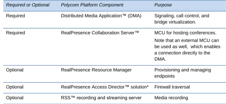
Table 1: RealPresence Platform Components
Required or Optional Polycom Platform Component Purpose
Required Distributed Media Application™ (DMA) Signaling, call control, and bridge virtualization.
Required RealPresence Collaboration Server™ MCU for hosting conferences. Note that an external MCU can be used as well, which enables a connection directly to the DMA.
Optional RealPresence Resource Manager Provisioning and managing
endpoints Optional RealPresence Access Director™ solution* Firewall traversal Optional RSS™ recording and streaming server Media recording
*An Acme Packet Net-Net Enterprise Session Director may alternately be used to secure firewall traversal.
The Services and Experience Portals interoperate with the RealPresence Platform components
along with the following standard IT infrastructure elements that the deploying organization
should provide:
Dynamic Host Configuration Protocol (DHCP) Allows the portals to obtain their IP
addresses.
Active Directory Server (LDAP) Enables integration with enterprise Active Directory
servers for user management and authentication.
Simple Mail Transport Protocol Server (SMTP) Enables sending email meeting
invitations and other notifications to users including login information and password
reset/updates.
HTTP Reverse Proxy Server Provides web clients with secure access to the
CloudAXIS portals from outside the organizational firewall. For best results, a proxy server
should be used that supports the Web Sockets protocol (
RFC 6455
).
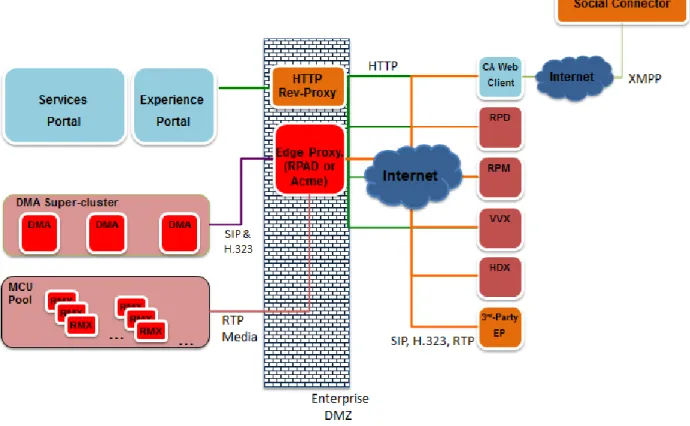
Note: Diagram Legend
The components in the following diagram are specified as follows:
CloudAXIS Components Identified by light blue.
Third-Party Components Identified by orange.
RealPresence Components Identified by bright red.
End-Points Identified by dark red.
Figure 1: Polycom RealPresence Platform
The RealPresence Platform components work with the CloudAXIS Suite to enable users to
create and participate in video conference meetings accessed from a web browser or other
hardware and software video endpoints, including mobile devices running the Polycom
RealPresence Mobile application. The meetings are scheduled in the Services Portal and run in
the Experience Portal. The Services Portal and Experience Portal run on one or more VMware
ESXi 5.x hosts. Scheduling a meeting in the Services Portal requires user or admin account
access (see
Understanding Account Roles
). Participating in meetings, however, only requires
access to a URL link sent in an email or instant message and a downloaded plug-in.
Users may be added to the Services Portal locally or through an integration with an enterprise
Active Directory (LDAP) server. If LDAP is configured, all enterprise users are allowed to use
their network credentials to access and host meetings on the Services Portal and to log into the
Experience Portal..
To create a scheduled meeting, users log in to the Services Portal, select their meeting options,
list the participants they want to invite, and then select the Schedule option. The Services Portal
then contacts the DMA system to create a Virtual Meeting Room (VMR) on an MCU for all
participants to join and an SMTP server sends out email notifications to each invited participant.
The invitation contains a URL, but can also contain information for SIP, H.323, and ISDN
access. When the meeting takes place, the DMA system validates the VMR and routes the call
to the destination RealPresence Collaboration Server.
When a user creates a meeting that starts immediately (ad-hoc), the user’s Experience Portal
launches and enables the user to begin inviting participants. The participants may be invited
from an aggregated list of the meeting creator’s Facebook, Google Talk™, and/or Skype™
contacts. Accessing Facebook, Google Talk™, and/or Skype™ contacts requires the Services
Portal administrator to enable and provision app-user credentials. Then, the user downloads
and installs a social plug-in to enable social integration by performing the following:
Google Talk™ Log into Google Talk™ service via the Experience Portal.
Facebook Log into Facebook service via the Experience Portal.
Skype™ Run the Skype™ software, log in to the Skype™ service via the Skype™
software, instruct the Portal to integrate with the Skype™ session and allow that
integration in the Skype™ client.
All of the meeting creator’s contacts that are currently online populate the contacts list in the
Experience Portal. When a contact is selected, a URL is sent to the contact on that particular
social IM. The invited participants click the URL or paste it in to their browser to gain access to
the meeting.
If a Polycom RSS server has been configured for the environment hosting the meeting, the
creator of the meeting may select the record meeting option, which records all aspects of the
meeting including all video streams, audio streams, and shared content.
The Services Portal and Experience Portal are each packaged in an .OVA file and must be
deployed on VMware ESXi hosts using vSphere tools. For example, VMware vCenter using the
vSphere client. Before deployment, be sure all the minimum requirements are met as outlined in
the next section.
Understanding the Minimum Requirements
Before deploying the Services Portal and Experience Portal, you must complete the setup
worksheets and meet the requirements listed in Table 2. To complete the setup worksheets, see
Completing the Setup Worksheet.
Table 2: Minimum Requirements
Component Description
RealPresence Platform Functioning RealPresence Platform with DMA and sufficient MCU capacity to meet your requirements. For more info, please see Understanding the Polycom RealPresence Platform.
Component Description
.OVA Latest Experience Portal .OVA file, downloaded to your local machine from the Polycom support site.
Latest Services Portal .OVA file, downloaded to your local machine from the Polycom support site.
One or more ESXi hosts Must be version 5.0 or higher.
Using a vSphere client, you must be able to access and administer your VMware ESXi hosts either directly or via a vCenter controlling the hosts.
VMware vSphere vCenter controller
Optional
Dynamic Host Configuration Protocol (DHCP)
Allows the portals to obtain their IP addresses.
LDAP Server (Optional) Enables Enterprise user’s authentication using their network credentials. Note that the Services Portal currently supports integration with only Microsoft Active Directory.
This feature also enables administrators to import Enterprise LDAP server users. The administrator can edit the imported user’s role or set the user status as inactive. For information on user roles, see Understanding Account Roles. For information on changing imported user accounts, see Editing Accounts Created from the Active Directory.
SMTP Server Enables the Services Portal to deliver email meeting invites and other notifications such as user onboarding.
Edge Proxy If providing access to external guests, a functioning firewall/NAT traversal element such as RealPresence Access Director or. Acme Packet Net-Net Enterprise Session Director is required (see Understanding the Polycom RealPresence Platform). This element should be provisioned to allow SIP guest access (required) and H.323 access (optional) to your DMA and MCUs.
HTTP Reverse Proxy If providing access to external guests, a functioning HTTP reverse proxy is required. This element should be provisioned to allow HTTPS and web socket access to the Experience Portal and HTTPS access to the Services Portal (optional).
Minimum Server Requirements
The Services Portal and Experience Portal in the Polycom® RealPresence® CloudAXIS™ Suite
are deployed as two virtual machine instances (one for the Services Portal and one for the
Experience Portal). Each instance must meet the requirements in the following table.
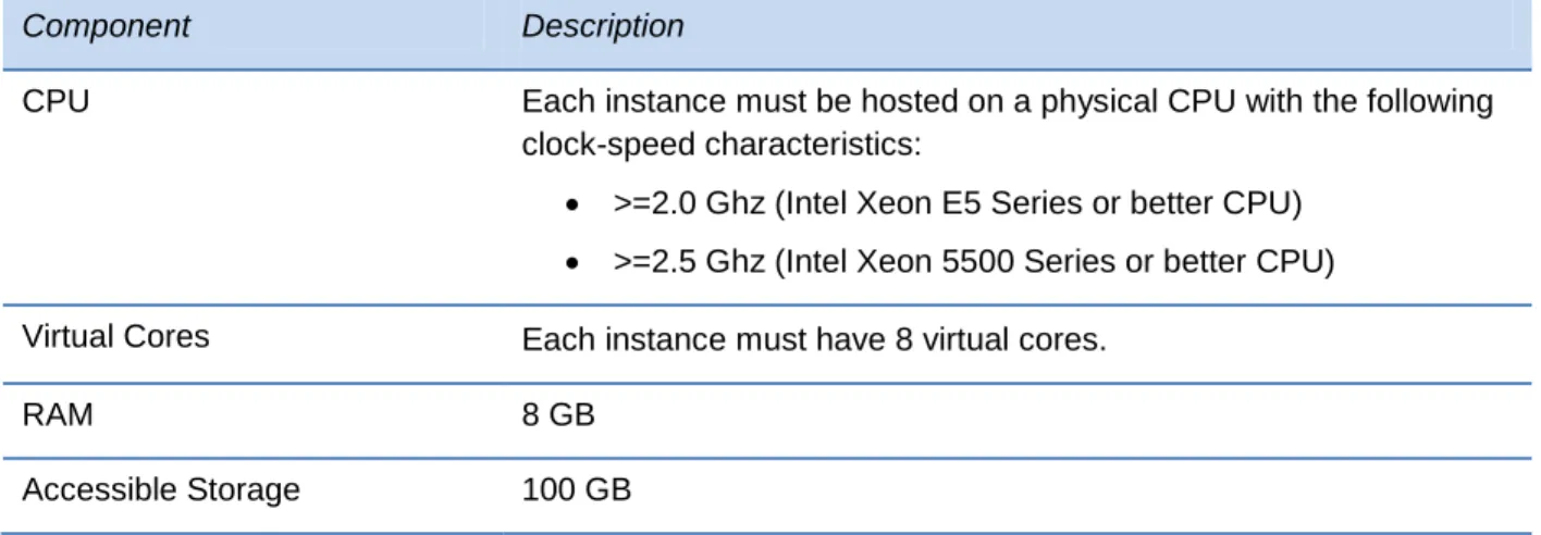
Table 3: Server Components per VM InstanceComponent Description
CPU Each instance must be hosted on a physical CPU with the following clock-speed characteristics:
>=2.0 Ghz (Intel Xeon E5 Series or better CPU) >=2.5 Ghz (Intel Xeon 5500 Series or better CPU) Virtual Cores Each instance must have 8 virtual cores.
RAM 8 GB
Accessible Storage 100 GB
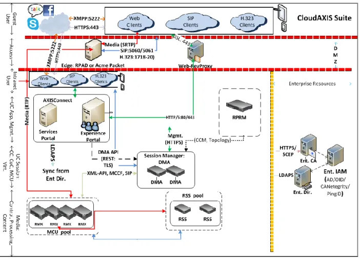
Learning the Port Usage
Figure 2: Port Usage Diagram
Table 4: Port Usage Inbound
Protocol/Function Component Ports
HTTP/HTTPS To provide access to the UI and
REST APIs.
80 is enabled but redirects to 443.
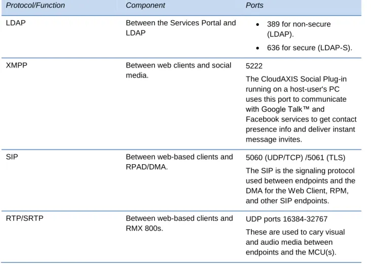
Table 5: Port Usage Outbound
Protocol/Function Component Ports
SMTP Between the Services Portal and
SMTP server
25 for non-secure (SMTP).
587/465 for secure (SMTP-S).
Protocol/Function Component Ports
LDAP Between the Services Portal and
LDAP
389 for non-secure (LDAP).
636 for secure (LDAP-S).
XMPP Between web clients and social
media.
5222
The CloudAXIS Social Plug-in running on a host-user's PC uses this port to communicate with Google Talk™ and
Facebook services to get contact presence info and deliver instant message invites.
SIP Between web-based clients and
RPAD/DMA.
5060 (UDP/TCP) /5061 (TLS) The SIP is the signaling protocol used between endpoints and the DMA for the Web Client, RPM, and other SIP endpoints.
RTP/SRTP Between web-based clients and
RMX 800s.
UDP ports 16384-32767 These are used to cary visual and audio media between endpoints and the MCU(s).
Completing the Setup Worksheets
Before you begin the Services Portal deployment, complete the fields in the
My System Values
column of the
Setup Worksheets
. As you progress through the configuration, use the
information in these worksheets as a reference.
Table 6: Setup Worksheet for the LDAP Server Configuration
LDAP Options My System Values Description
Server Enter the FQDN or IP address of
the LDAP Server.
Secure Select to establish a secure
LDAP Options My System Values Description
Port Enter the port number to connect
to the LDAP Server. Typical values:
389 for non-secure (LDAP).
636 for secure (LDAP-S).
BaseDN Specify the distinguished name
(DN) of a subset of the Active Directory hierarchy. This determines the set of users that are able to schedule meetings via the Services Portal.
Username Enter the LDAP service account
user ID.
Password Enter the login password for the
service account user ID.
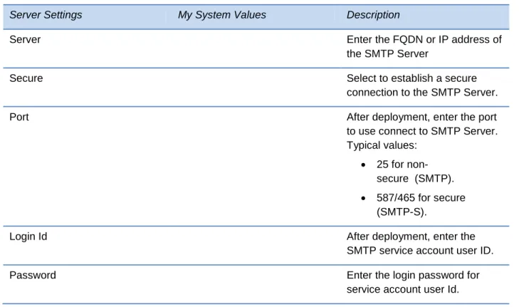
Table 7: Setup Worksheet for the SMTP Server Configuration
Server Settings My System Values Description
Server Enter the FQDN or IP address of
the SMTP Server
Secure Select to establish a secure
connection to the SMTP Server.
Port After deployment, enter the port
to use connect to SMTP Server. Typical values:
25 for non-secure (SMTP). 587/465 for secure
(SMTP-S).
Login Id After deployment, enter the
SMTP service account user ID.
Password Enter the login password for
Server Settings My System Values Description
Sender Mail Id Enter the email ID to be used as
the return address for
notifications sent by the Services Portal. This will typically be configured as a “null” or “no reply” address.
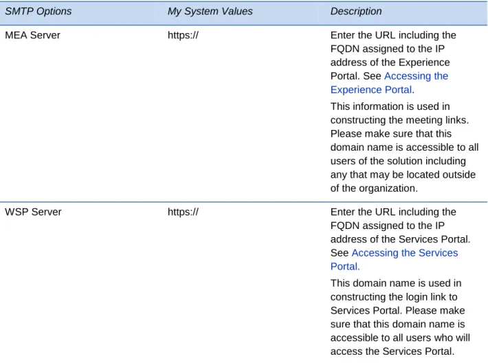
Table 8: Setup Worksheet for the Server Settings
SMTP Options My System Values Description
MEA Server https:// Enter the URL including the
FQDN assigned to the IP address of the Experience Portal. See Accessing the Experience Portal.
This information is used in constructing the meeting links. Please make sure that this domain name is accessible to all users of the solution including any that may be located outside of the organization.
WSP Server https:// Enter the URL including the
FQDN assigned to the IP address of the Services Portal. See Accessing the Services Portal.
This domain name is used in constructing the login link to Services Portal. Please make sure that this domain name is accessible to all users who will access the Services Portal.
Table 9: Setup Worksheet for the DMA Configuration System Configuration
Information
My System Values Description
Name Enter a ‘nickname’ to assign to
the DMA system to distinguish it in the Services Portal
configuration.
Host Enter the FQDN or IP address of
an individual DMA or the FQDN of the supercluster's virtual address if the DMA is part of a supercluster.
Port Enter the TCP port number to
use when communicating with the DMA system.
Typically, you will specify port 8443 (corresponding to the https REST API for the DMA system).
System Configuration Information
My System Values Description
VMR Prefix Enter the VMR prefix that
corresponds to this DMA system. This is optional and for use in environments where a dialing plan is used to assign different VMR IDs to be handled by a peered set of DMA
systems. Specifying this value allows the portals to know where to direct API requests
concerning a particular VMR ID. For example, if DMA-1 had the dialing prefix specified as “1” and DMA-2 had no dialing prefix specified, all portal requests concerning VMRs with ID “1xxxx” would be directed to DMA-1 and requests concerning any other VMR ID would be directed to DMA-2.
Note that the VMR prefix must match what’s on the DMA. To set this up this value, see the
Polycom DMA 7000 System Operations Guide on the Polycom Support site.
Default Admin Enter a user account name with
an administrative role that exists on the DMA system.
Note that if the DMA system is configured to have multiple domains, make sure that the admin user account has access to all the domains and hence can search the VMRs of all users. This typically requires a domain account rather than a local DMA account.
Also note that the DMA system must have an MCU Pool order named ‘Factory Pool Order’. See the Polycom DMA 7000 System Operations Guide for more on adding MCU Pool orders.
System Configuration Information
My System Values Description
Admin Password Enter the password value
defined on the DMA system for the Default Admin account.
Owner Domain Enter the domain of the user
account assigned for creating meetings in the DMA system. For local domains, enter “LOCAL.”
Owner Username Enter the username assigned for
creating meetings in the DMA system. The username must match the name of a user account defined on the DMA system. The user does not need to be an administrator.
For information on how to create a username for the DMA system, see the Polycom DMA 7000 System Operations Guide on the Polycom Support site.
Generate VMR From Range This is a checkbox option.
Selecting this box displays two text boxes for entering a range. This option is used by admins to allow the Service Portal to randomly generate VMRs on the DMA within a specified range. This allows admins to separate the VMRs used with meetings that start immediately from permanent VMRs on same DMA.
Note that the range must be all positive numbers with a maximum of 10 digits. The first text box is for the lowest of the range and the second text box is for the highest. As an example, entering a range of 123 to 1234, the Services Portal will generate VMRs between 123 and 1234.
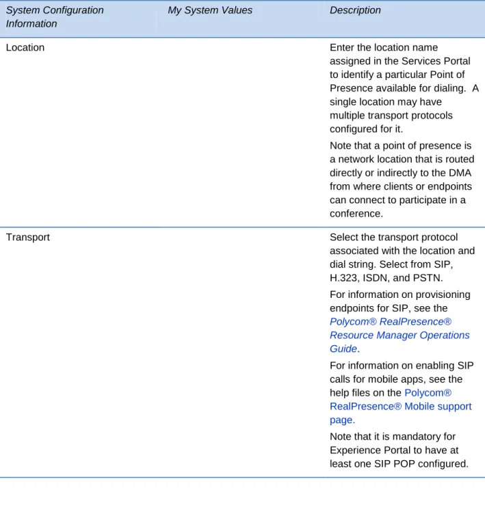
Table 10: Setup Worksheet for the DMA Server Point of Presence Configuration System Configuration
Information
My System Values Description
Location Enter the location name
assigned in the Services Portal to identify a particular Point of Presence available for dialing. A single location may have
multiple transport protocols configured for it.
Note that a point of presence is a network location that is routed directly or indirectly to the DMA from where clients or endpoints can connect to participate in a conference.
Transport Select the transport protocol
associated with the location and dial string. Select from SIP, H.323, ISDN, and PSTN. For information on provisioning endpoints for SIP, see the
Polycom® RealPresence® Resource Manager Operations Guide.
For information on enabling SIP calls for mobile apps, see the help files on the Polycom® RealPresence® Mobile support page.
Note that it is mandatory for Experience Portal to have at least one SIP POP configured.
System Configuration Information
My System Values Description
Dialstring Dialstrings (SIP URI, H.323
E.164 enum, PSTN phone number) are used by a video or audio endpoint to join a
conference hosted by the DMA. Typically for SIP and H.323 callers, this string includes the address or domain name (preferred) of the edge traversal device (RPAD or Acme)
provisioned to allow external access to this DMA.
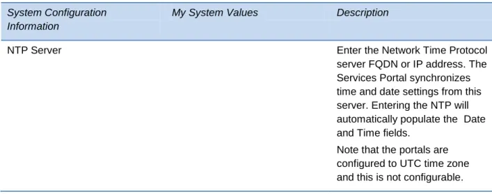
Table 11: Setup Worksheet for the Date Time Configuration System Configuration
Information
My System Values Description
NTP Server Enter the Network Time Protocol
server FQDN or IP address. The Services Portal synchronizes time and date settings from this server. Entering the NTP will automatically populate the Date and Time fields.
Note that the portals are configured to UTC time zone and this is not configurable.
Chapter 2: Deploying and Configuring the
Services Portal and Experience Portal
The Services Portal and Experience Portal require deployment on a VMware EXSi host using a
vSphere Client administrative GUI. Deploy the Services Portal first then the Experience Portal.
Once they are both deployed, log in to the Services Portal with the default super admin
credentials and configure the server settings then complete the Experience Portal
configurations. When the configurations are complete, the Services Portal is ready for adding
and managing users. Once users receive access, they can use the Services Portal to create
meetings and add contacts and use the Experience Portal to enable conference interaction. You
can find information on accessing and using the Services Portal as a user in the
RealPresence®
CloudAXIS™ Suite User Guide
.
This chapter shows you how to deploy and configure the Services Portal. Before you begin,
confirm the prerequisites and complete the Setup Worksheets provided in
Getting Started
.
See the steps for deploying and configuring the Services Portal in the following sections of this
chapter.
1
Deploying the Services Portal and Experience Portal Packages
2
Accessing the Services Portal
3
Accessing the Experience Portal
4
Configuring the Services Portal
5
Configuring the Experience Portal
Deploying the Services Portal and Experience Portal
Packages
Before you begin, confirm that you meet the prerequisites listed in
Getting Started
then deploy
the Services Portal and Experience Portal .OVA files to your
VMware vCenter
.
Note that when the portal instances boot up, they will each attempt to obtain an IP address via
DHCP. The instance IP address and MAC address can be determined by accessing the
instance information using the vSphere Client. It is recommended that the instance IP
assignments be made permanent by modifying your DHCP server’s configuration to map the
current IP address or another preferred address of your choosing to the respective instance
MAC address. Then, reboot the instance if necessary for it to obtain a new address.
It is also recommended that you modify your DNS server settings to assign a domain name to
each instance based on the permanent IP address you have selected.
Note: Order of Deployment
The packages may be deployed, accessed, and configured in any logical relative order.. The order described in this document is recommended for those unfamiliar with the overall process, however.
Accessing the Services Portal
Obtain the Services Portal FQDN from your DNS server, open a browser, and enter the FQDN
in the address bar. The Services Portal login screen displays, and you are now ready to
configure the Services Portal for use. For the first Services Portal login, use admin/admin, then
accept the End User License Agreement (EULA). Until the EULA is accepted, no further action
can be taken.
After accepting the EULA, change the password for security. For changing passwords, see
Changing Your Password
.
Note that you should activate the Services Portal license before beginning the configuration
process. To activate the license, see
Activating the Services Portal License
.
Troubleshooting: URL (FQDN) Does Not Respond
If the Services Portal URL does not respond and open the Services Portal login screen, confirm that the Nginx, Apache, or all servers are running as follows:
To check the Nginx, Apache, or all servers:
1
Using your SSH client, access the Services Portal FQDN.2 Login as a priveleged administrator using [caxis/caxis].
3 Get status:
○ Enter the following to get the Nginx status: service nginx status ○ Enter the following to get the Apache status: services tomcat6 status
○
Enter the following to get the status on all servers: service --status-all4 Start servers if they are not running and restart them if they are running but you are still having problems with the link:
○ Start up servers: services <SomeServer> start ○ Restart servers: services <SomeServer> restart
Note: Configuration Note
The FQDN is required when configuring the Services Portal. Enter the Services Portal FQDN you noted in the Setup Worksheet for the Server Settings.
Activating the Services Portal License
When the Services Portal is first accessed and the End User License Agreement is accepted
and the
Activate License
alert, shown next, displays at the top of the screen. You should
activate the license before configuring the Services Portal. Activating the license requires having
an account on the
Polycom Support
site. If you do not have an account, create one now.
This section explains the process for activating your license. Before you begin, locate your
license number in your CloudAXIS product documentation.
Figure 3: Activate License Alert
To activate the license:
1
On the
Actice License
alert, click Activate Now.
The
License
screen displays the serial number, shown next. Keep this screen open
2
Open a new browser page, sign in to the
Polycom Support
, hover your mouse over
License & Product Registration to display menu options, then select
Activation/Upgrade.
3
Select Site & Single Activation/Upgrade.
4
In the
Site & Single Activation/Upgrade
screen’s
Serial Number
text box, enter the serial
number from the
License
screen displayed in step 1 and click Accept Agreement.
5
Enter the license number from your Polycom CloudAXIS product documentation into an
The key code displays.
6
Enter the key code in the
License
screen’s
Activation Key
text box, displayed in step 1,
and click Activate.
The license is now activated.
Accessing the Experience Portal
Obtain the Experience Portal FQDN from your DNS server, open a browser, and enter the
FQDN in the address bar.
The full URL of the server is
https://<Server FQDN>:9445
.
Note: Configuration Note
The FQDN is required when configuring the Experience Portal. Enter the Experience Portal FQDN in the Setup Worksheet for the Server Settings
To directly call a VMR, enter the URL
https://<Server FQDN>.
No additional port number is
needed.
Activating the Experience Portal License
When the Experience Portal server is online, the Polycom System Administration application
launches in your default browser with an alert to activate your license at the top of the screen.
You must activate the license before configuring the Experience Portal. Note that activating the
license requires having an account on the
Polycom Support
site.
This section explains the process for activating your license. Before you begin, locate your
license number in your CloudAXIS product documentation; this is the same product
documentation used for
Activating the Services Portal License
.
To activate the license:
1
Log in to the Polycom System Administration app. For first time login, use the default
credentials: admin/admin.
Admin Tip: Admin Credentials
After logging in with default credentials, change your password. See Changing the System Administration Application Password
2
In the System Administration app, select Maintenance > Tools > Read Serial Number,
shown next.
3
Select Go. Your serial number is displayed.
4
Open a new browser page, sign in to the
Polycom Support
site, hover your mouse over
License & Product Registration to display menu options, select Activation/Upgrade.
5
Select Site & Single Activation/Upgrade.
6
In the
Site & Single Activation/Upgrade
screen’s
Serial Number
text box, enter the serial
number from step 3 and click Accept Agreement.
7
Enter the license number from your Polycom CloudAXIS product documentation into an
empty
License Number
text box and click Activate.
The key code displays.
8
In the System Administration app, select Settings > Admin UI and locate the
License Key
text entry box.
9
Enter the key code from step 7 in the
License Key
text box and click Submit.
The license is now activated.
Configuring the Services Portal
The Services Portal supports three types of accounts: super admin, admin, and user. Each
account type provides a different level of access. Only super admin accounts have access to
the Services Portal
Platform Settings
screen. You must log in as a super admin to configure and
update the Services Portal settings. For information on the account roles, see
Understanding
Account Roles
.
For first-time configurations, log in to the default super admin account and enter the LDAP,
SMTP, core settings, and DMA system information in the Services Portal
Settings
screen. This
information enables user management and video conference meeting creation and
management functionalities.
This section shows you the steps for configuring the Service Portal. Before you begin, you must
deploy the Services Portal and Experience Portal packages as described in
Deploying the
Services Portal and Experience Portal Packages.
Perform the first-time configuration steps in the following order:
1
Logging in as the Super Admin
3
Configuring the Connection to the SMTP Server
4
Configuring Additional Server Settings
5
Configuring Social Policies
6
Configuring the Connection to the
DMA System and RPAD Servers
7
Setting Date and Time
8
Managing Certificates
9
Selecting and Downloading Log Level
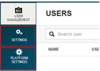
Logging in as the Super Admin
You must log in as a super admin to configure or update the Services Portal settings. The super
admin account has special access to the Settings and Platform Settings tabs, shown next. For
first-time configurations, log in with the default super admin credentials (Username/Password:
admin/admin) then change the password for security. For changing passwords, see
Changing
Your Password
.
Figure 4: Super Admin Tabs
Admin Tip: Creating Additional Super Admins
When the Services Portal is launched for the first time, it is recommended that you create another super admin account after the configuration is completed. See Creating Accounts for more information. Login with the new super admin credentials and delete the default super admin account for secure access.
Configuring Connection to the LDAP Server
The LDAP server enables the Services Portal to import external user accounts, edit external
user account default roles, set external user accounts as active or inactive, and authenticate
user logins. This section shows you how to configure connection to the LDAP server. You must
log in as a super admin before configuring this connection. For more information, see
Logging in
as the Super Admin.
Note: Setup Worksheet
This section specifically refers to information entered in the Setup Worksheet for the LDAP Server Configuration. Complete the worksheet in advance and use it as a reference during the configuration process and to obtain information about each field.
To configure the connection to the LDAP server:
1
Select Settings > Core
Settings > LDAP. The
LDAP Settings
screen displays, shown
next.
2
Enter the following in the
LDAP Settings
screen:
○
Server Enter the LDAP FQDN or IP address.
○
Secure Check the checkbox to establish a secure connection. This is optional but
recommended.
○
Port Enter the LDAP port number (typically 636 for secure and 389 for non-secure).
○
BaseDN Enter the distinguished name entered in the
Setup Worksheet for the LDAP
Server Configuration
.
○
Username Enter the LDAP services account user ID for system access to the Active
Directory.Password Enter the login password for the LDAP services account user ID.
3
Click Update to finish the configuration or Reset to populate the fields with the most
Configuring the Connection to the SMTP Server
The SMTP server enables the Services Portal to send email notifications to users when their
account is created, when their account details are updated, when they are invited to a meeting,
or when a meeting they created or have been invited to is updated or cancelled. This section
shows you the steps for configuring the connection to the SMTP server. You must log in as a
super admin before configuring the SMTP server. For more information, see
Logging in as the
Super Admin.
Note: Setup Worksheet
This section specifically refers to information entered in the Setup Worksheet for the SMTP Server Configuration. Complete the worksheet in advance and use it as a reference during the configuration process and to obtain information about each field.
Note: Active Directory Users
Because the Services Portal considers all imported Active Directory users to have enabled accounts until explicitly disabled, emails are not sent when an Active Directory user is imported.
To configure the connection to the SMTP server:
1
Select Settings > Core Settings > SMTP. The
SMTP Settings
screen displays, shown
next.
2
Enter the following in the
SMTP
Settings
screen:
○
Server Enter the SMTP FQDN or IP address.
○
Secure Check the checkbox to establish a secure SMTP-S/SSL connection. This is
optional but recommended if the SMTP server supports secure connection.
○
Port Enter the SMTP port number (typically 25 for non-secure SMTP and 587 or 465
for SMTP-S) .
○
Login Id Enter the SMTP service account user ID. This is not required for non-secure
connection.
○
Password Enter the service account user ID login password. This is not required for
non-secure connection.
○
Sender Mail Id Enter the email ID used to send notifications.
3
Click Update to finish the configuration or Reset to populate the fields with the most
recently updated SMTP information.
Configuring Additional Server Settings
This section shows you how to enter the locations of the Services Portal and Experience Portal
servers. The purpose of each server follows:
Web Services Portal (WSP) Server Hosts the Services Portal.
Meeting Experience Application (MEA) Server Hosts the Experience Portal.
Before you begin, you must be logged in to the Services Portal as a super admin. For more
information, see
Logging in as the Super Admin
.
Note: Setup Worksheet
This section specifically refers to information entered in the Setup Worksheet for the Server Settings. Complete the worksheet in advance and use it as a reference during the configuration process and to obtain information about each field.
To configure the additional server settings:
1
Select Settings > Core Settings > Server Settings. The
Server Settings
screen displays,
shown next.
2
Enter the following in the
Server
Settings
screen
○
MEA Server
Enter the Experience Portal’s FQDN from
Accessing the Experience
Portal
.
○
WSP Server Enter the Services Portal’s FQDN from
Accessing the Services Portal
.
3
Click Update to finish the configuration or Reset to populate the fields with the most
recently updated Server Settings information.
Configuring Social Policies
Users can send conference invitations in an instant message to any online contacts listed in
their Skype™, Facebook, and/or Google Talk™ accounts. How you enable access to social
contacts depends on which social connector(s) you want to use:
Skype™
To enable access to Skype™ contacts, select the
Skype
checkbox in the
Social Policy
page.
Google Talk™
Enabling access to Google Talk™ contacts requires the following steps:
a
Create a Google Talk™ app. See
Appendix A: Creating a Google Talk™ App
. This app
is only enabled to share the contacts lists while keeping the usernames, passwords,
and other information private.
b
Select the Google_Talk™ checkbox in the
Social Policy
page.
c
Enter the app ID and App Secret, retrieved from step 10 of
Appendix A: Creating a
Google Talk™ App
.
Enabling access to Facebook contacts requires the following steps:
a
Create a Facebook app. See
Appendix B: Creating a Facebook App.
This app is only
enabled to share the contacts lists while keeping the usernames, passwords, and other
information private.
b
Select the Facebook checkbox in the
Social Policy
page.
c
Enter the app ID and App Secret, retrieved from step 4 of
Appendix B: Creating a
Facebook App.
.
Note: CloudAXIS Social Plug-in
Accessing any of the social connectors also requires the CloudAXIS Social Plug-in; this plug-in is downloaded when a user accesses the Experience Portal menu’s Contacts option. For more information, see the RealPresence® CloundAXIS™ User Guide.
This section shows you how to enable and disable Skype™, Facebook, and/or Google Talk™
account access in the Services Portal. Before enabling access to Google Talk™ contacts, you
must create a Google Talk™ app. See
Appendix A: Creating a Google Talk™ App
for more
information
.
Before enabling
Facebook contacts, you must first create a Facebook app. See
Appendix B: Creating a Facebook App
for more information.
Note that you must log in to the Services Portal as a super admin before entering the social
policy settings. For more information, see
Logging in as the Super Admin
.
To configure social policies:
1
Select Settings > Social Policy. The
Social Policy Settings
screen displays, shown next.
Skype™, Facebook, and Google Talk™ options are displayed.
2
Click the checkboxes for Skype™, Google Talk™, and/or Facebook to select or deselect
the social policy options. Selecting a checkbox enables users to access the account type’s
contact list from the Experience Portal; deselecting disables users from accessing the
account type’s contact list from the Experience Portal.
When selecting Google Talk™ and/or Facebook, the
App ID
and
App Secret
text boxes
display, shown next.
Enter the following:
○
Google_Talk™
When selecing Google Talk™, enter the following information:.
»
App ID
Enter the Client ID from step 10 of of
Appendix A: Creating a Google
Talk™ App.
»
App Secret
Enter the Client Secret from step 10 of
Appendix A: Creating a Google
Talk™ App.
○
When selecing Facebook, enter the following information:
»
App ID
Enter the App ID and from step 4 of
Appendix B: Creating a Facebook App.
»
App Secret
Enter the App Secret from step 4 of
Appendix B: Creating a Facebook
App.
3
Click Update.
Configuring the Connection to the DMA System and RPAD Servers
This section shows you how to enter the configuration details for your DMA system, RPADs,
and points of presence.
The DMA system enables the Services Portal to launch online video conference meetings, the
RPAD is an external link to the DMA that enables firewall traversal, and a point of presence
enables you to route directly or indirectly to the DMA. As an example, a point of presence
configured with an FQDN that points to the RPAD externally and points to the DMA from within
the Polycom network enables the Services Portal to communicate with the DMA from either side
of a firewall.
You must log in to the Services Portal as a super admin before entering the server settings. For
more information, see
Logging in as the Super Admin
.
Note: Setup Worksheet
This section specifically refers to information entered in the Setup Worksheet for the DMA Configuration. Complete the worksheet in advance and use it as a reference during the configuration process and to obtain information about each field.
To configure the connection to the DMA system:
1
Select Settings > DMA Config. The
DMA Config Settings
screen displays, shown next.
2
Click +Another DMA. A group of text boxes displays on the screen, shown next.
3
Enter the following in the
DMA Config
screen options:
○
Name Enter the name to this DMA system.
○
Host Enter the DMA system interface FQDN.
○
Port Enter “8443” as the DMA system communication port.
○
VMR Prefix Enter the VMR prefix configured on the DMA system, maxium 4 digits
.
This is optional. Note that a personal VMR will only work if it exists on the DMA system.
○
Default Admin Enter the DMA system admin user name.
○
Admin Password Enter the DMA system admin account password.
○
Owner Domain Enter the domain of the owner who creates the meetings.
○
Owner Username Enter the user name of the owner who creates the meetings.
○
Generate VMR range Select to enter the range of numbers allowed for generating
VMRs. When selected, two text boxes display, shown next:
4
Click + Another POP to enter your point of presence information. The
Point of Presence
Note: Point of Presence
A point of presence is a network location that is routed directly or indirectly to the DMA from where clients or endpoints can connect to participate in a conference
The points of presence are configurable as follows: Direct connection to DMA.
Externally to access the DMA via h.323 video border proxy.
Externally routed via SIP Session Board Controller (SBC) including Polycom Real Presence Access Director (RPAD) or any third-party session boarder controller. ISDN.
Audio dial-in via Public Switch Telephony Network (PSTN).
The client or end point could be the CloudAXIS Experience Portal, a seperate soft client such as Polycom RealPresence Mobile, a hardware appliance such as Polycom Group Series or a telephone
Enter your point of presence information from the
Setup Worksheet for the DMA Server
Point of Presence Configuration
as follows:
Note: Entering Points of Presence (POP)
Enter the POPs in the order you want the Services Portal to use first. For example, internal POPs should be entered first. Also note that it is mandatory to add at least one SIP POP.
○
Location Enter the geographic location name of the URI
.
This is optional.
○
Transport Select the protocol associated with the access point (SIP, H323, ISDN,
PSTN).
○
Dialstring Enter the string associated with the protocol that is configured to have
access to DMA system externally.
Click +Another POP to enter another point of presence as needed.
5
Click Configure.
Setting Date and T
i
me
The Services Portal uses a Network Time Protocol Server (NTP Server). This section shows
you how to set the date and time for the Services Portal.
Note: Setup Worksheet)
This section specifically refers to information entered in the Setup Worksheet for the Date Time Configuration. Complete the worksheet in advance and use it as a reference during the configuration process and to obtain information about each field..
To set the date and time:
1
Select Platform Settings > Date Time. The
Date Time
screen displays, shown next.
2
The
Date Time
screen displays the following text boxes:
○
NTP Server Enter NTP server IP address or FQDN to synchronize the time on
Services Portal system.
○
Time Zone Nothing needs to be entered in this field. This field displays the time zone
of the Services Portal.
○
Date & Time Nothing needs to be entered in this field. This field displays the time of
the Services Portal.
Managing Certificates
The Services Portal requires a secure connection. When a secure connection is established, the
browser receives a self-signed certificate or a certificate signed by a third party Certificate
Authority verifying the identity of the Services Portal.
This section shows you how to generate self-signed certificates and certificate sign requests
(CSRs); how to view, download, and delete certificates; and how to upload third-party signed
and trust certificates to the Services Portal.
Generating Certificates and CSRs
This section shows you how to generate self-signed certificates and certificate sign requests
(CSRs). You must send the CSRs to a third party Certificate Authority for a digital signature then
upload the signed certificate. For uploading certificates, see
Uploading Certificates
.
Note that you must log in as a super admin to create certificates and CSRs. To determine your
account type, see
Understanding Account Roles.
Caution: Overwrite Warning
Be sure you need a new certificate or CSR before following this procedure. Generating a new certificate or CSR overwrites the previous. To check, see Viewing, Downloading, and Deleting Certificates.
Note: Other Requirements
The certificates created from CSRs generated by the Services Portal will only authenticate the user connection to the Services Portal. A separate CSR needs to be externally
generated for the Experience Portal and RealPresence components. Send the externally generated CSR to a Certificate Authority, then upload the signed certificate and key to the components and Services Portal. For uploading to the Services Portal, see Uploading Certificates.
To generate certificates and CSRs:
1
Select Platform Settings > Certificate > Generate CSR/Certificate. The
Certificate
Management
screen displays, shown next.
2
Enter the following in the
Certificate Management
screen:
○
Operation Type
Select the
Operation Type
drop-down and choose one of the
following:
»
CSR
Generates a Certificate Signing Request (CSR). Send the CSR to a Third
Party Certificate Authority for a digital signature then upload the signed certificate to
the server. For uploading, see
Uploading Certificates
.
○
Type
Select the drop-down and select WebServer.
○
Organization
Enter your organization name.
○
Organizational Unit
Enter your organization unit information.
○
Country
Enter the two letter ISO code for your organization’s country.
○
State
Enter your state with full spelling.
○
Location
Enter your organization’s city or location.
○
Sub Alternate Name
Enter the list of host names protected by this certificate. The
host names must be separated by commas.
3
Click Generate.
Note: Restart Services Portal Server
After generating your certificate, the Services Portal server must be restarted to recognize the certificate. Note that a restart is not needed for generating CSRs.
To restart:
1 Using your SSH client, access the Services Portal FQDN.
2 Login as a priveleged administrator using [caxis/caxis].
3
Restart servers: services <SomeServer> restartViewing, Downloading, and Deleting Certificates
Super admins use the certificate list to confirm if a certificate is needed and to delete obsolete
certificates. This section shows you how to view, download, and delete certificates in the
Services Portal.
To view, download, or delete certificates and CSRs:
1
Select Platform Settings > Certificate > Certificate List. The
Certificate List
screen is
shown next. Any existing certificates are displayed.
2
Select one of the following options:
○
View
Click to view and/or download the certificate.
To download:
1. After selecting View, copy the entire hash from --- BEGIN CERTIFICATE to ---
END CERTIFICATE.
2. Paste the text in to a text file.
3. Rename the extension .cer.
If the file is a CSR, you can now send the file to a third-party CA for signing.
○
Delete
Click to delete the certificate. This option is only available to WebApp-trust
certificates. Webserver certificates can only be regenerated or uploaded as a Certificate
Authority signed certificate. For generating WebApp certificates, see
Generating
Certificates and CSRs.
Caution: Deleting Trust Certificates
Deleting trust certificates can break the chain of certificate trust.
Uploading Certificates or Certificate Chain
The Services Portal enables super admin users to upload two types of required certificates: third
party certificates signed by a Certificate Authority and trust certificates. Upload the signed
certificate to establish a secure communication with users and verify the identity information of
Services Portal servers. Upload the trust certificate for servers that require secure
communication such as the Active Directory server, SMTP server, and DMA system. This
section shows you how to upload signed third party and trust certificates to the Services Portal.
To upload certificates:
2
Perform the following:
a
To upload a third-party signed certificates
1. Select the
WebServer Own
option in the
Type
drop-down menu.
2. Click the
icon.
3. Navigate to the certificate or certificate chain and select Open.
4. Click Upload.
b
To upload a trust certificate.
1. Select the
WebServer Trust
option in the
Type
drop-down menu.
2. Click the
icon.
3. Navigate to the certificate and select Open.
4. Click Upload.
Note: Restart Services Portal Server
After uploading your certificate, the NGINX and Tomcat servers must be restarted to recognize the certificate.
To restart:
1
Using your SSH client, access the Services Portal FQDN.2 Login as a priveleged administrator using [caxis/caxis].