Design of the Single Leg of the Quadruped Bionic Robot with Jumping
Liang-Wen WANG
a,*, Kang-Kang SONG
b, Feng ZHAO
c,
Wen-Liao DU
dand Xin-Jie WANG
eSchool of Mechanical and Electrical Engineering, Zhengzhou University of Light Industry, Zhengzhou, China
a[email protected], b[email protected], c[email protected],d[email protected], e[email protected]
Keywords: Quadruped bionic robot, Single leg, Energy storage unit, Jumping.
Abstract. In order to achieve jumping movement gait of a quadruped bionic robot, herein, a kind of quadruped bionic robot with a single leg is designed for the purpose. The body, thigh, shin, ankle and the structure of the energy storage unit are determined by analyzing the bone structure and the muscle distribution of a four-legged mammal. The energy storage unit is set on the each joint, by instantaneously releasing energy, the position relations are rapid changed between the two structure units on which the energy storage unit is connected. The structure can realize the jumping by simulating the bionic mammal’s muscles tensioning and relaxing. In this paper, the energy storage unit composes of mechanical and electronic integration mode, the spring of the storage energy, the electromagnetic clutch, and the servo motor control that controls the movement of the structure. The movement is controlled by a servo motor. The walking robot that uses the designed leg structure can satisfy the requirements of certain environment and task. The modular structures simplify the structure and the control of the robot, which reduce the research and use-cost.
Introduction
Compared to wheel robot and crawler robot, the walking robot shows more flexibility and environment adaptability in the ground of the non-continuous environment. Jumping movement is typical movement pattern for four-legged animal to realize fast moving and cross obstacles, which also is the expected target for the movement ability of the quadruped robot with high performance. In terms of the structure design, the existing jumping robots mostly adopt bionic structure, which makes full use of the animal structure form of the natural selection [1-3].
In 2002, Prof Hvon, etc. designed the one leg robot with jumping, which imitated the dog's hind legs, used a spring as tendons. To realize jumping, the spring was used to provide impetus, the tendons was usedas a buffering device after landing [4-8]. According to the cheetah’s leg bone structure, Ananthanarayanan, etc. adopted the tendon bone co-location system, considered the balance between weight and strength, researched the bionic legs that was suitable for high speed running [9]. Younse, etc. developed the six foot jumping robot by using fiber glass springs. The glass springs were arranged on both ends of the legs to store energy. The ropes connected the end of the leg, and twined on a reel. The reel was driven by a motor when need, the clutch, which connected the motor and the reel, is separated to release energy and realize jumping [10]. After this, a quadruped robot which used the dynamic gait as the main movements came out [11-12]. A single leg system of the quadruped robot and a single foot jumping robot are also studied in the domestic [13-14]. Hydraulic drive, because of its high output and light weight, is widely used in quadruped robots represented by Big Dog in recent years. The team of Seminic has done the related research about single leg system design and bounce experiment before developed hydraulic drive quadruped bionic robot HyQ [15].
Because the jump process of the robot is a dynamic process which needs transiently large amounts of power, the output power of motor driven by traditional way is hard to meet the requirements. The hydraulic drive’s structure and control system are complex, and have large
volume, which have many shortcomings if the structures are used in walking robot. Thus, the energy storage unit is set on the each joint, by instantaneously releasing energy, the position relations are rapid changed between the two structure units on which the energy storage unit is connected. By this way, the structure can simulate the bionic mammals’ muscles to realize the jumping of the leg.
Configuration Analysis of a Quadruped Bionic Robot The Structural Characteristics of Four-Legged Mammal
Cheetah is the fastest four-legged mammal in the world. By the research of the morphology and anatomy of the cheetah, the fore leg and hind leg joints for the cheetah usually adopt the configuration mode which knee and elbow show the opposite vertex, this configuration contributes to improve the stability of pitch movement of the cheetah (shown in Figure 1.).
Fig.1. Bone structure of a Cheetah
Cheetah legs include hip, knee and ankle joints, which have four degrees of freedom (The hip joint includes two degrees of freedom, knee joint includes one, and ankle contains one). In the process of walking of the cheetah, the shoulder blade and the pelvis expand the movement space of their legs. The leg with multiple degrees of freedoms makes cheetahs possess good adaption to all kinds of terrain. It is more flexible to adjust the body posture and movement gait for the cheetahs. The ankle connects a achilles tendon, which is the elastic energy storage component, it has played a large role in the animals running to enhance the buffer when animal lands on the ground. The skeletal muscle structure of cheetah is a good reference for the design of the quadruped bionic robot.
The DOF Configuration of a Single Leg of the Robot
The structure of the single leg of the quadruped robot is designed to imitate the biological prototype of the cheetah. The simplified structure of the single leg adopt the configuration mode which knee and elbow show the opposite vertex as the structure of cheetah’s leg.
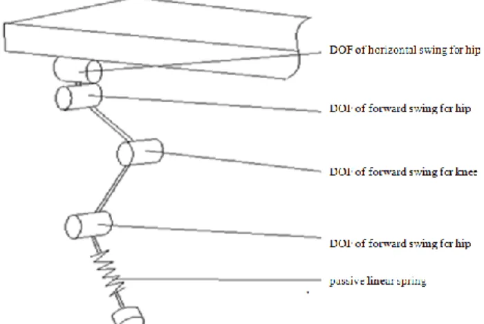
The fore legs and hind legs of the robot have same structures. The legs of robot are divided into four parts. The first part is a two freedom degrees structure that simulates the shoulder blade and pelvis. They are DOF of horizontal swing and DOF of forward swing of hip respectively. The DOF of horizontal swing of hip can enhance the ability of the robot under the influence of external yawing force. The second part, third part and fourth part respectively simulate the structure of the cheetah's legs, including the two DOFs of knee joint and ankle joint. In addition, the elastic element is configured to the end of the robot's leg to simulate the elastic part of the cheetah's achilles tendon, which is to reduce the impact force when the foot contacts with the ground. The DOF configuration of single leg for the robot is shown as in Figure 2.
Fig.2. The DOF configuration of single leg for the robot
The Design of the Bionic Robot Legs The structural Design of the Single Leg
The designed structure of the single leg is shown as in Figure 3.
Fig. 3. Overall structure of the robot single leg
The legs of the robot are composed of four parts. The body and leg, as well as the each segment on the leg are connected through rotary joint. The part between the ankle and foot end is elastic passive joints, the rest are active joints. Hip joint consists of two DOFs, which includes DOF of horizontal swing and DOF of forward swing for hip. DOF of horizontal swing for hip is driven by a servo motor. The end of hip is hinged with connecting frame on the rack through pin. The servo motor for horizontal swing is mounted on the rack, it’s output shaft is connected with hip joint by a coupling, which drive ship joint to rotate around the hip connecting frame for achieving horizontal swing hip movement. The thigh is consisted with the two side plates of the thigh fixedly connected through elongated cylindrical nuts and screws. The upper end of the thigh is connected to the hip. An energy storage unit is disposed between the hip and thigh. The energy storage unit drives the thigh to achieve forward swing movement. The two ends of the energy storage unit are connected with hip and thigh respectively. The structural design between the knee and the ankle are basically same.
The Structural Design of the Ankle
Fig.4.The structure of the ankle
The top end of the ankle is an ankle connecting part, which is connected with the ankle. The lower end of the ankle connecting part is designed as hollow structure. The side of the ankle connecting part has the ear plate to connect the energy storage unit of the ankle, the lower end has flange to connect spline bushing of the ankle. The spline bushing is fixedly connected with ankle connecting part by hexagon bolts. A spline shaft is installed inside the spline bushing, and slides along the centerline of the spline bushing, which can ensure the deformation direction of the spring. The upper end of spline shaft is installed with locking slotted round nut, and the lower end is installed with spring preload nut. Between the spline bushing and the spring preload block, there exists the straight linear spring. The spring is set on spline shaft, and retracts or extend along the spline shaft center line, which can reduce the impact of foot end with the ground and realize recycling use of energy for dynamic gait .The end of the spline shaft is installed with the end connecting part, which is fixedly connected with three-dimensional force sensor to measure the contact force of foot. The lower end of three-dimensional force sensor connects with damping rubber block to improve the buffering capacity and friction.
The Structural Design of the Energy Storage Unit
The energy storage unit includes an guide sleeve of energy storage. The guide sleeve has a left end cover and a right end cover at left and right sides. The covers are fixed tightly with the guide sleeve by locking screws. The outside of the left end covers fixes a left connection rod of the energy storage unit. The left connection rod is connected to the energy storage unit bracket. The energy storage spring is set inside the guide sleeve of the energy storage unit. A piston is installed at one end of the storage spring, and fixedly connected with sliding guide rod which locates piston centerline. A gear rack is fixedly installed on the sliding guide rod, which mesha gear shaft located at inner side of the right end covers.The guide sleeve of energy storage unit is provided with cushion fixed to the flanges of its inner wall. At the right of the energy storage unit, worm and gear reducer house is provided. Worm and gear reducer flange connect with each other. They are mounted on the basis. The input end of worm and gear reducer is provided with the servo motor of the reducer. The output shaft is provided with an electromagnetic clutch. Its input end is connected with the output shaft of worm and gear reducer. Its output end is connected with the right end of the gear shaft. The left and right sides of the gear shaft are provided by bearings. Its two ends are provided with a spring retainer ring to limit axial movement of the bearing. The spring retainer ring is mounted in the specific cylindrical bore of reducer mount. The right end of gear shaft is connected to the angle encoder. A through hole is provided in the right end cover of energy storage
unit for the slide guide rod and the rack passing. The end of the slide guide rod through the through hole is connected to the energy storage unit bracket.
Fig.5. The structure of energy storage unit
Conclusion
In this paper, the single leg of the quadruped robot is designed to achieve the skip motion. For the designed structure, the energy storage unit between the joint and the electromagnetic clutch realize the instantaneous motion by release the stored energy. This method can quickly change the movement position of the two structural elements between the energy storage unit and the simulate body muscles. Therefore, the single leg can achieve skip function. By using this structure, walking robot can be realized to meet some requirements of the environment and tasks. In addition, the modular structure can simplify the whole structure and can control of the robot. The consideration between cost of researching and using is suitable.
Acknowledgments
This work is supported by support plan of Innovation Science Team of Henan Province , Key Technology Research Project of Henan Province(152102210145) and Doctoral Research Funded Projects of Zhengzhou University of Light Industry.
References
[1] Brown, Ben, and Garth Zeglin. “The bow leg hopping
robot.” RoboticsandAutomation,1998.Proceedings.1998 IEEE International Conference on. Vol. 1.IEEE, 1998.
[2] Schmiedeler, James Patrick. The mechanics of and robotic design for quadrupedal galloping. Diss. The Ohio State University, 2001.
[3] Hyon, S-H., S. Kamijo, and T. Mita. “Kenken'-A biologicallyinspiredone-legged runningrobot.”JOURNAL-ROBOTICS SOCIETY OF JAPAN 20.4 (2002): 103-112.
[4] Hyon, S. H., T. Emura, and T. Mita. “Dynamics-based control of a one-legged hopping robot.” Proceedings of the Institution of Mechanical Engineers, Part I: Journal of Systems and
[5] Hyon, Sang-Ho, and Takashi Emura. “Energy-preserving control of a passive one-legged running robot.” Advanced Robotics 18.4 (2004): 357-381.
[6] Hyon, Sang-Ho, and Takashi Emura. “Running control of a planar biped robot based on energy-preserving strategy.” Robotics and Automation, 2004.Proceedings.ICRA'04.2004 IEEE International Conference on. Vol. 4.IEEE, 2004.
[7] Hyon, Sang-Ho, and Tsutomu Mita. “Development of abiologically inspired hopping robot-” Kenken”.”Robotics and Automation, 2002.Proceedings.ICRA'02.IEEE International Conference on.Vol. 4.IEEE, 2002.
[8] Hyon, Sang-Ho, Jun Morimoto, and Mitsuo Kawato. “From compliant balancing to dynamic walking on humanoidrobot:Integrationof CNS and CPG.”Robotics and Automation (ICRA), 2010 IEEE International Conference on.IEEE, 2010.
[9] Ananthanarayanan, Arvind, MojtabaAzadi, and Sangbae Kim. “Towardsabio-inspiredlegdesignfor high-speed running.” Bioinspiration& biomimetics7.4 (2012): 046005.
[10] Younse, Paulo, and HrandAghazarian. “Steerable hopping six-legged robot.”SPIE Defense and Security Symposium. International Society for Optics and Photonics, 2008.
[11] Palmer III, Luther R., and David E. Orin. “Force redistribution in a quadruped running trot.” Robotics and Automation, 2007 IEEE International Conference on.IEEE, 2007.
[12] Hutter, Marco, et al. “Scarleth: Design and control of a planar running robot.”Intelligent Robots and Systems (IROS), 2011 IEEE/RSJ International Conference on.IEEE, 2011.
[13] Zhao, Mingguo, et al. “Control algorithm based on time event for a pneumatic single-legged hopping robot.” Jiqiren(Robot) 34.5 (2012): 525-530.
[14]Wang, Xin, et al. “Bio-inspired controller for a robot cheetah with a neural mechanism controlling leg muscles.” Journal of Bionic Engineering 9.3 (2012): 282-293.
[15] Semini, Claudio, et al. “HyQ-Hydraulically actuated
quadrupedrobot:Hoppingleg prototype. ”Biomedical Robotics and Biomechatronics, 2008.BioRob 2008.2nd IEEE RAS & EMBS International Conference on.IEEE, 2008.