ISSN: 2277 – 9043
International Journal of Advanced Research in Computer Science and Electronics Engineering (IJARCSEE)
Volume 2, Issue 2, February 2013
137
All Rights Reserved © 2013 IJARCSEE
LIBRARY AUTOMATION SYSTEM
Chesti Altaff Hussain
1P.Gopi Raghavendra
2V.Mani Kumar
3V.Swapna priya
41
Assistant Professor, Department of ECE, Bapatla Engineering College, Bapatla-522101
2
Final Year, Department of ECE, Bapatla Engineering College, Bapatla-522101
3
Final Year, Department of ECE, Bapatla Engineering College, Bapatla-522101
4
Final Year, Department of ECE, Bapatla Engineering College, Bapatla-522101
ABSTRACT–– This paper is based on RFID technology and
using 8051 microcontroller. Automation tasks such as searching a particular book available in the library from the main system and even from our home by sending SMS using mobile are performed. User can get a book issued without any manual interference by showing it to the RF reader, it will automate the details and one can return the book simply by showing the book to the system and dropping into the book drop counter and then the system automatically updates the book availability and user’s details. User can enter into the library by showing entry card and he cannot bring out the book from the library without registering, because it detects the book automatically and updates into his account, if account is full it does not open the door. Red and green LED’s are used to represent whether the door is open or not.
I. INTRODUCTION
The acquired books in a library are arranged according to the library classification, ―LIBRARY AUTOMATED SYSTEM‖ is an advanced digital security and automatic management system, and it can be used in the libraries to reduce the manual interference to maximum extent, whenever a new book is acquired by the library. An RFID tag is attached into the book with the relevant information like, book name, book number, etc. The detailed information regarding the book is also stored in the embedded system Data base. User details are also stored in system. Each user is supplied with a smart card. These smart cards carry identification data.
The system will automate the following tasks using RFID technology and using 8051 microcontroller:
It contains an administrative ID card by using this ID card only new user id registration and new book registration will be done. To access the system first one needs to show his RF ID tag, if it is a user ID card then it will allow the user to access the system and it shows the options,
Submission
Issue
If the ID card is an administration ID then it shows the options
Book registration
User registration
User can able to get all information regarding how many copies of a book are presently available by entering the book name in the system. And if any user want to verify particular book is available in the library from his home (USING GSM): one needs to send a message of book number or name using mobile then the system verifies the availability of the book and sends the status of the book to the user.
When a user wants to get a book issued: user can get it done without any manual interference. First user needs to shows his id card in front of the system and then it opens users account and shows options. User needs to select issue option and then he needs to show the book then it will automatically update into his account.
When a user wants to return books: user needs to choose return option and then he needs to show the book and should drop in book drop counter and the books automatically are adjusted for return against the user’s name.
User can enter into the library by showing his ID card only and he cannot bring out the book from the library without registering, because it detects the book automatically and updates into his account, if account is full it does not open the door and LED is used to represent whether the door is open or not.
II. WORKING
1. For registration of new book and new user:
Book Registration: When book registration option is selected then it waits for books scanning after showing the new book with RFID strip then it will asks book type after selecting the book type with the keypad, it will automatically update the available status of the books.
ISSN: 2277 – 9043
International Journal of Advanced Research in Computer Science and Electronics Engineering (IJARCSEE)
Volume 2, Issue 2, February 2013
138
All Rights Reserved © 2013 IJARCSEE
automatically creates new user account then with this ID user can access the system, and user can take books in his account.
8051
Embedded
Controller
(Atmel)
KEY PAD
LCD (16x2)
GSM
EPROM
RED LED
RF-ID READERMobile
GREEN LED
8051
Embedded
Controller
(Atmel)
LCD(16x2)
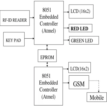
Figure 1: Block Diagram of Library Automation System
2. Verification
If any user wants to verify in which locker particular book is available, first he needs to show his RF ID tag, if it is a user ID card then it will allows to access the system and it shows the options. User needs to select issue option then it shows the book details and number of books issued in his account. And then user needs to enter exit switch.
Figure 2: book issuing process
3. If any user wants to verify in which locker particular book is available
First he needs to show his RFID tag, if it is an user ID card then it will allows to access the system and it shows the options. User needs to select issue opinion then it shows the book details and number of books issued in his account, and then user needs to press exit switch
4. If user wants to take a book in his account
First he needs to show his RF ID tag, if it is a user ID card then it allows accessing the system, and it shows the options. User needs to select issue option, and then it shows the book details and number of books issued in his account. Then he needs bring the book from the rack and should show the book in front of the system then it will read the book name and number and it will be update in his account (EPROM). If account is full it does not allow him to take the book.
Figure 3: Book Returning
5. If user wants to return the book
First he needs to show his RF ID tag, if it is an user ID card then it will allows to access the system and it shows the options. He need to select return option, and then he needs to show the book then it will read the book name and number and it will delete its details from his account, and it will update the book available details in to the server.
ISSN: 2277 – 9043
International Journal of Advanced Research in Computer Science and Electronics Engineering (IJARCSEE)
Volume 2, Issue 2, February 2013
139
All Rights Reserved © 2013 IJARCSEE
6. Self check
User can enter into the library by showing his ID card only, and he cannot bring out the book from the library without registering, because it automatically update into his account, if account is full it will not open the door and LED is used to represent whether the door is open or not.
III. RFID
RFID technology for self-check in and check out of the users from library and for self-maintenance of the data related to the books borrowed by the user. The full form of an RFID is radio frequency identification. RFID is an automatic identification method, relying on storing and remotely retrieving data using devices called RFID tags or transponders. RFID technology includes two devices called RFID reader and RFID tag. RFID tag is an object placed into a product, animal, or person for the purpose of identification and tracking using radio waves. RFID readers are used to read the tags. Some of the tags can be read by the RFID reader several meters away and beyond the line of sight of the reader. RFID tags are of two types. They are active and passive. ―Passive‖ tags have no battery and "broadcast" their data only when energized by a reader. That means they must be actively polled to send information. "Active" tags are capable of broadcasting their data using their own battery power. In general, this means that the read ranges are much greater for active tags than they are for passive tags perhaps a read range of 100 feet or more, versus 15 feet or less for most passive tags. The extra capability and read ranges of active tags, however, come with a cost; they are several times more expensive than passive tags. Today, active tags are much more likely to be used for high-value items or fixed assets such as trailers, where the cost is minimal compared to item value, and very long read ranges are required. Most traditional supply chain applications, such as the RFID-based tracking and compliance programs emerging in the consumer goods retail chain, will use
the less expensive passive tags. These RFID systems are
electronically programmed with unique information. In market we can find different verities of RFID systems. They are categorized according to their frequency ranges. Some of the most commonly used RFID kits are
1. Low-frequency (30 KHz to 500 KHz) 2. Mid-Frequency (900 KHz to 1500MHz) 3. High Frequency (2.4GHz to 2.5GHz)
These frequency ranges mostly tell the RF ranges of the tags from low frequency tag ranging from 3m to 5m, mid-frequency ranging from 5m to 17m and high frequency ranging from 5ft to 90ft. The cost of the system is based according to their ranges with low-frequency system ranging from a few hundred dollars
to a high-frequency system ranging somewhere near 5000 dollars.
RFID mainly consists of three components. They are: 1. An antenna or a coil,
2. A transceiver with decoder and 3. A transponder which is an RF tag.
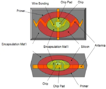
Figure 5: RF ID system
1. Antenna
140
All Rights Reserved © 2013 IJARCSEE
2. TAGS (Transponders)
An RFID tag is comprised of a microchip containing
identifying information and an antenna that transmits this data wirelessly to a reader. At its most basic, the chip will contain a serialized identifier, or license plate number, that uniquely identifies that item, similar to the way many bar codes are used today. A key difference, however is that RFID tags have a higher data capacity than their bar code counterparts. This increases the options for the type of information that can be encoded on the tag, including the manufacturer, batch or lot number, weight, ownership, destination and history (such as the temperature range to which an item has been exposed). In fact, an unlimited list of other types of information can be stored on RFID tags, depending on application needs. An RFID tag can be placed on individual items, cases or pallets for identification purposes, as well as on fixed assets such as trailers, containers, totes, etc. Tags come in a variety of types, with a variety of capabilities. Key variables include:
"Read-only" versus "read-write" here are three options in terms of how data can be encoded on tags: (1) Read-only tags contain data such as a serialized tracking number, which is pre-written onto them by the tag manufacturer or distributor. These are generally the least expensive tags because they cannot have any additional information included as they move throughout the supply chain. Any updates to that information would have to be maintained in the application software that tracks SKU movement and activity. (2) "Write once" tags enable a user to write data to the tag one time in production or distribution processes. Again, this may include a serial number, but perhaps other data such as a lot or batch number. (3) Full "read-write" tags allow new data to be written to the tag as needed—and even written over the original data. Examples for the latter capability might include the time and date of ownership transfer or updating the repair history of a fixed asset. While these are the most costly of the three tag types and are not practical for tracking inexpensive items, future standards for electronic product codes (EPC) appear to be headed in this direction.
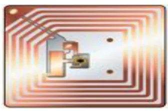
Figure 6: RFID tag
3. RF Transceiver
The RF transceiver is the source of the RF energy used to activate and power the passive RFID tags. The RF transceiver may be enclosed in the same cabinet as the reader or it may be a
separate piece of equipment. When provided as a separate piece of equipment, the transceiver is commonly referred to as an RF module. The RF transceiver controls and modulates the radio frequencies that the antenna transmits and receives. The transceiver filters and amplifies the backscatter signal from a passive RFID tag.
IV. GSM MODULE
GSM stands for Global System for Mobile communication. The Main working of this GSM module in the project is to help the users to find weather the book is present in the Library or not, just by sending a message from his Mobile phone from any place to the server such that he gets a reply about the status of the book. GSM is mostly used since it has high digital calling capability, text messaging, too economical in the field of communication and also capable to provide services even in Roaming. It can be easily interfaced with RS232 cable.
Definitions: The words, ―Mobile Station‖ (MS) or ―Mobile Equipment‖ (ME) are used for mobile terminals supporting GSM services. A call from a GSM mobile station to the PSTN is called a ―mobile originated call‖ (MOC) or ―outgoing call‖, and a call from a fixed network to a GSM mobile station is called a ―mobile terminated call‖ (MTC) or ―incoming call‖. The details of the GSM module used in this project is given below
GSM modem characteristics
Dual Band or Tri band GSM GPRS modem (EGSM 900/1800MHz) / (EGSM 900/1800 / 1900 MHz) Designed for GPRS, data, fax, SMS and voice
applications
Fully compliant with ETSI GSM Phase 2+ specifications (Normal MS)
General characteristics
Input voltage: 8V-40V
Input current: 8mA in idle mode, 150mA in communication GSM 900 @ 12V
Input current: 8mA in idle mode, 110mA in communication GSM 1800 @ 12V
Temperature range: Operating -20 to +55 degree Celsius; Storage -25 to +70 degree Celsius
Overall dimensions: 80mm x 62mm x 31mm / Weight: 200g
Interfaces
ISSN: 2277 – 9043
International Journal of Advanced Research in Computer Science and Electronics Engineering (IJARCSEE)
Volume 2, Issue 2, February 2013
141
All Rights Reserved © 2013 IJARCSEE
Power supply through Molex 4 pin connector SMA antenna connector
Toggle spring SIM holder Red LED power on
Green LED status of GSM and GPRS Module: Several AT commands are used for the working and test the GSM module.
For the working of this GSM module we need a SIM (Subscriber Identity Module) card. There is software functions relying on positive reading of the hardware SIM detect pin. This pin state (open/closed) is permanently monitored. When the SIM detect pin indicates that a card is present in the SIM connector, the product tries to set up a logical SIM session. The logical SIM session will be set up or not depending on whether the detected card is a SIM Card or not
Figure 7: GSM modem
If the SIM detect pin indicates ―absent‖, the response to AT+CPIN? Is ―+CME ERROR 10‖ (SIM not inserted). If the SIM detect pin indicates ―present‖, and the inserted Card is a SIM Card, the response to AT+CPIN? Is ―+CPIN: xxx‖ depending on SIM PIN state.
If the SIM detect pin indicates ―present‖, and the inserted Card is not a SIM Card, the response to AT+CPIN? Is CME ERROR 10.
In this way we have several AT commands to test GSM module.
V. KEYPAD
Four switches are used as keypad which is used to select the options
VI. LCD DISPLAY
LCD is a type of display used in digital watches and many portable computers. LCD displays utilize to sheets of polarizing material with a liquid crystal solution between them. An electric current passed through the liquid causes the crystals to align so that light cannot pass through them. Technical achievement has resulted in brighter displace, higher resolutions, reduce response times and cheaper manufacturing process.
1. LCD PIN diagram
Most of the LCD modules conform to a standard interface specification. A 14pin access is provided having eight data lines, three control lines and three power lines. The connections are laid out in one of the two common configurations, either two rows of seven pins, or a single row of 14 pins.
Figure 8: Intelligent LCD display
PIN SYMBOL I/O DESCRIPTION
1 Vss -- Ground
2 Vcc -- +5Vpower supply
3 Vee -- Power supply to control contrast
4 RS I RS=0 to select command register
RS=1 to select data register
5 R/W I R/W=0 for write
R/W=1 for read
6 EN I/O Enable
7 DB0 I/O The 8-bit data bus
8 DB1 I/O The 8-bit data bus
9 DB2 I/O The 8-bit data bus
142
All Rights Reserved © 2013 IJARCSEE
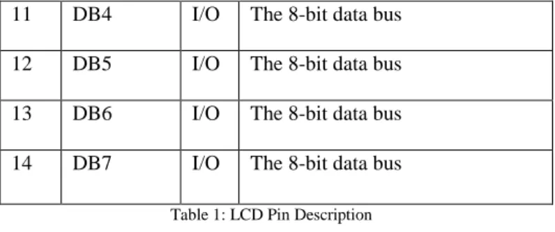
11 DB4 I/O The 8-bit data bus
12 DB5 I/O The 8-bit data bus
13 DB6 I/O The 8-bit data bus
14 DB7 I/O The 8-bit data bus
Table 1: LCD Pin Description
2. Basic commands of LCD
When LCD is powered up; the display should show a series of dark squares, possibly only on part of display. These characters are actually in their off state, so the contrast control should be adjusted anti-clockwise until the squares are just visible. The display module resets itself to an initial state when power is applied, which curiously the display has blanked off so that even if characters are entered, they cannot be seen. It is therefore necessary to issue a command at this point, to switch the display on. For a LCD module to be used effectively in any piece of equipment, a microprocessor or a micro controller is usually required to drive it. However, before attempting to wire the two together, some initial experiments can be performed by connecting a series of switches to the pins of the module. This can be a quite beneficial step, if even you are thoroughly conversant with the workings of microprocessors.
VII. ELECTRICALLY ERASABLE PROGRAMMABLE ROM (EPROM-24C08)
Two-wire Serial Interface.
Bidirectional Data Transfer Protocol.
Write Protect Pin for Hardware Data Protection. Internally Organized 128 x 8 (1K), 256 x 8 (2K), 512 x
8 (4K), 1024 x 8 (8K) or 2048 x 8 (16K).
The AT24C08 provides 16384 bits of serial electrically erasable and programmable read-only memory (EEPROM) organized as 2048 words of 8 bits each. The device is optimized for use in many automotive applications where low-power and low-voltage operation are essential.
Figure 9: AT24C08 EEPROM pin diagram:
Pin Name Function
A0-A2 Address Inputs
SDA Serial Data
SCL Serial Clock Input
WP Write Project
NC No Connect
Table 2: Pin Functions
1. DEVICE OPERATION
Clock and data transitions: Data on the SDA pin may change only during SCL low time periods. Data changes during SCL high periods will indicate a start or stop condition.
Start Condition: A high-to-low transition of SDA with SCL high is a start condition which must precede any other command.
Stop Condition: A low-to-high transition of SDA with SCL high is a stop condition. After a read sequence, the stop command will place the EEPROM in a standby power mode.
Acknowledgement: All addresses and data words are serially transmitted to and from the EEPROM in 8-bit words. The EEPROM sends a ―0‖ to acknowledge that it has received each word. This happens during the ninth clock cycle.
Standby Mode: The AT24C08 features a low-power standby mode which is enabled: (a) upon power-up and (b) after the receipt of the STOP bit and the completion of any internal operations.
ISSN: 2277 – 9043
International Journal of Advanced Research in Computer Science and Electronics Engineering (IJARCSEE)
Volume 2, Issue 2, February 2013
143
All Rights Reserved © 2013 IJARCSEE
are considered the most significant bits of the data word address which follows. The A0, A1 and A2 pins are no connected. The eighth bit of the device address is the read/write operation select bit. A read operation is initiated if this bit is high and a write operation is initiated if this bit is low. Upon comparison of the device address, the EEPROM will output a ―0‖. If a comparison is not made, the chip will return to a standby state.
2. INTERFACING AT24C08 SERIAL EEPROM WITH AT89C51 MICROCONTROLLER
Serial memory devices offer significant advantages over parallel devices in applications where lower data transfer rates are acceptable. In addition to requiring less board space, serial devices allow microcontroller I/O pins to be conserved.
Hardware: A typical interconnection between an AT89C51 microcontroller and an AT24C08 serial EEPROM may share the bus, up to eight members of the AT24CXX family utilizing the same two microcontroller I/O pins. Each device on the bus must have its address inputs (A0, A1 and A2) hard-wired to a unique address. The first device recognizes address zero (A0, A1, A2 tied low), while the eighth recognizes address seven (A0, A1, A2 tied high).
Bi-directional Data Transfer Protocol: The Bi-directional Data Transfer Protocol utilized by the AT24CXX family allows a number of compatible devices to share a common 2-wire bus. The bus consists of a serial clock (SCL) line and a serial data (SDA) line. The clock is generated by the bus master and data is transmitted serially on the data line, most significant bit first, synchronized to the clock. The protocol supports bi-directional data transfers in 8-bit bytes.
In this application, the microcontroller serves as the bus master, initiating all data transfers and generating the clock which regulates the flow of data. The serial devices present on the bus are considered slaves, accepting or sending data in response to orders from the master. The bus master initiates a data transfer by generating a start condition on the bus. This is followed by transmission of a byte containing the device address of the intended recipient. The device address consists of a 4-bit fixed portion and a 3-bit programmable portion. The fixed portion must match the value hard-wired into the slave, while the programmable portion allows the master to select between a maximum of eight slaves of similar type on the bus.
VIII. CONCLUSION
This paper is to provide efficient and automated way of security for libraries, This system can be a commercial one and when this system is sold, then the person who purchases this system becomes the administrator and he is provided an admin
RFID card for new user and book registration, GSM, RF ID card reader modules make this project strong enough in its security with included ease of operation techniques, Books and user information is automatically updated, LCD displays the details processing.
IX. FUTURE SCOPE
This paper can be extended with biometric authentication like finger print and IRIS scan to make this system robust and reliable making a safe and secure use of technology in our daily life for library management, searching also can be done through internet and storing the user details.
REFERENCES
1. Muhammad Ali Mazidi and JanicaGillispie Mazidi, ―The 8051 Microcontroller and Embedded Systems‖, New Delhi
2. microID125KHz RFID System Design Guide 3. M.Morris Mano, ―Digital Design‖, New Jersey 4. Micro processor Interfacing Programming and
Hardware by Douglas V. Hall 5. www.atmel.com
6. www.maxim-ic.com 7. www.temperature.com 8. www.alldatasheets.com 9. www.gsm.com
10. www.RS232tutorial.com
11. The89C51 Microcontroller-Architecture, Programming & Applications-Kenneth J Ayala Second Edition ; Pen ram International
12. The 89C51 Microcontroller –ATMEL, Designer’s data sheets.
13. Ramesh,S.Goankar; Microprocessor Architecture Programming and Applications with the 8085; 4th Ed.; Penram International Publishers.
14. htttp://www.gsmworld.com 15. http://rfid.net/
16. http://www.rasilant.com/taglibrary.html 17. http://www.edaxis.in/Libbest.pdf
18. http://www.indiamart.com/prometheus-infotech/rfid-management-solutions.html
19. http://www.slideshare.net/kunalbabre/rfid-library-management-presentation
20. http://eprints.rclis.org/15253/3/RFID.pdf 21. LibBest: Library Management System:
http://www.rfid.library.com
22. http://www.ibit-soft.com/Products_RFID_LMS.html 23. Linear Integrated Circuits –D.RoyChowdhury&Shail
144
All Rights Reserved © 2013 IJARCSEE
24. Karen Coyle, ―Management of RFID in Libraries‖ , Preprint version of article published in the Journal of Academic Librarianship, v. 31, n. 5, pp. 486-489 25. www.wikipedia.org - Library [last accessed on
20/2/2009]
26. Psion Teklogix handheld reader manual –
www.psionteklogix.com [last accessed on 20/2/2009] 27. Mercury 4 RFID reader manual –
www.thingmagic.com [last accessed on 20/2/2009] 28. Ayre, L.B. The Galecia Group Position paper: RFID
and libraries. Retrieved March 17, 2010
(http://www.galecia.com/weblog/mt/arcieves/cat.rfidan dwireless.php)
29. Boss, Richord W. RFID Technology for Libraries. 2009(http://www.ala.org/ala/pla/plapubs/technotes/rfidt echnology)
30. Firke, Yogaraj S. RFID Technology for library security. In emerging technology and changing dimensions of libraries and information service by Sanjay Kataria and others. New Delhi, KBD Publication.2010
31. Lindquist,M.G. RFID in libraries-Introduction to the issues. In world library and information congress paper presented at 69th IFLA general conference and council. 32. Berlin.1-9 August 2003 available at
http://ifla.queenslibrary.org/IV/ifla69/papers
33. Syed, S., 2005 Use of RFID Technology in libraries: a new approach to circulation, tracking, inventorying and security of library materials. Library Philosophy and Practice. 8(1), 15-21.
34. Jonathan Westhues’s Proximity Website 35. http://www.hbeonlabs.com/
36. http://www.maastechindia.com/robotics_and_Mechatro nics.html