CONTRIBUTIONS TO THE THEORETICAL ANALYSIS OF THE WORKING PROCESS MADE BY EQUIPMENT DESIGNED TO CHOP VEGETAL DEBRIS FOR FIELD
CLEARING
PhD. eng. PARIS DALADIMOS, PhD. eng. ALEXIOU ALEXANDROS
Keywords: working process, chopping, vegetal debris
ABSTRACT
This paper presents considerations on chop plant residues, focusing on physical values related to the cinematic apparatus for cutting and chopping, the influence of plant mass subjected to chop on the degree of chopping and of the processing speed of the aggregate and the influence the working speed on the degree of chopping.
INTRODUCTION
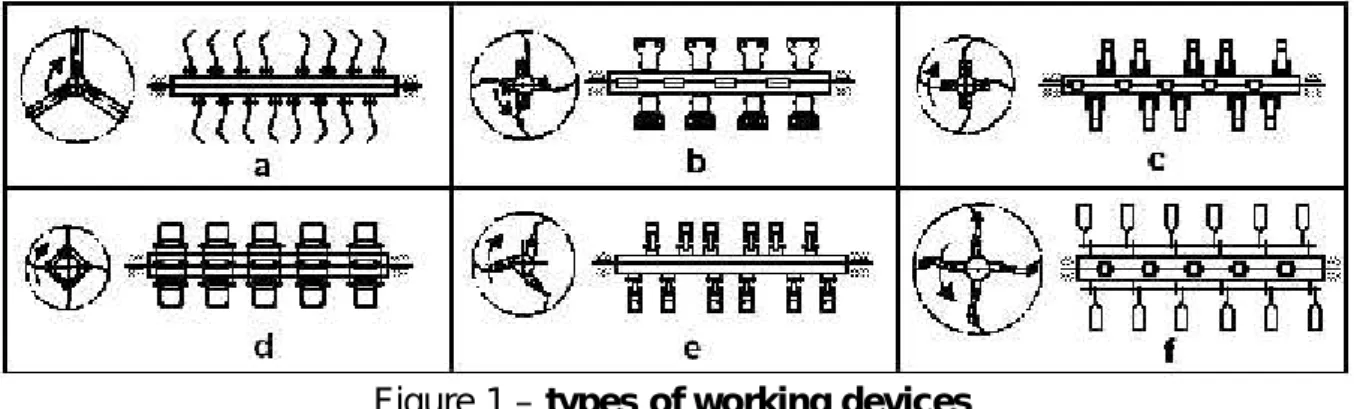
As a principle, a device for cutting-chopping from technical equipment designed for gathering and chopping vegetal debris or fodder is formed of shaft or action drum, working devices (knives) and framework. The working devices are jointed mounted on the shaft or drum (figure 5.1.) by bolts or a axle and fixing bridle. The working devices can be, as a rule, knives or jointed bars with inertial mass (hammers) and they are mounted along the drum on 2-4 rows placed after a helix with a single outset. Between the passings of two next elements there is a covering zone of 7-25 mm. The chopping devices with jointed knives have a diameter at the margin of knives of D = 450-710 mm, rotation of n = 1600-2300 rot./min, the working width (the length of the drum L = 1400-2100 mm. The power needed for driving the drum is P=18-33kW. The working devices can be made of a single piece or of more pieces (plinth, knife, linkage arm and ear).
Figure 1 – types of working devices
The active part can be: curved knife with straight edge (a), straight knife with declined edge (b), reversible knife, etc. (figure 5.2.).
Figure 2 –Knife models
functions. They make the cutting-chopping of plants and throwing the chopped material in the trailer or, with the case of cutting machineries, the spreading of chopped material evenly on the soil surface.
MATERIAL AND METHOD
With the machineries of cutting and chopping vegetal debris in order to clear the field the cutting device has the axle of the rotor placed horizontally and in normal position (perpendicular) on the direction of rolling.
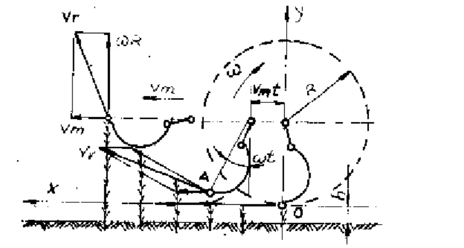
Figure 3 -The kinematics of the device for cutting and chopping
In these conditions, the movement equations of a point from the knife, placed at radius r[0,R], (R is the radius of the edge point of the knife), are:
sin
(1 cos
)
mx
v t
r
t
y
r
t
,And the components of the speed:
cos ,
sin
x m y
v v R t
v R t
The absolute speed of the knife (the speed of plants cutting or the resulting speed) is given by the following relation:
2 2 2 2 2 2
2 cos 1 2 cos
r x y m m m
v v v v r v r t v t (1)
where: λ represents the kinematic regime of the device and it has the following form: p
m m
v
r
v
v
(2)In order to ensure an inertial cutting, which means without plinth (or without counter knife) there is need that the speed of knives to be superior to a limit speed at which the inertial cutting is made, namely:
lim
p
v
v
(3)where: vlim is the speed at which the inertial cutting is made. Generally, vIim= 8-12 m/s. In
practice, the effective speed of cutting is higher than the limit speed.
p
v
R
where:ωis the angular speed of a point located on the edge of the knife;
R is the radius of the circle described by a point located on the edge of the knife. Generally,ωR= 30 ÷ 50 m/s.
During the action of the knives on plants they are tilted in the direction of machinery movement. After machinery passing the stalks get back to the former position and this fact determines the increasing of the height of the stubblehmin comparison with a set up working
heighth. This increasing can be measured byεcoefficient that represents the ratio between the effective height of the stubblehmand the set up working heighth:
ε= hm/ h (4)
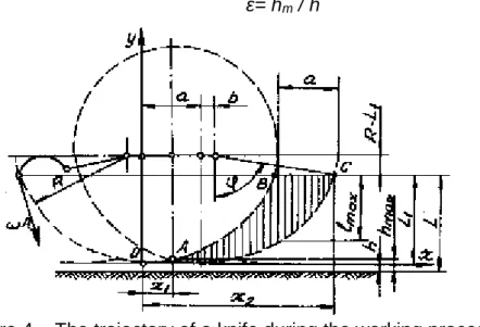
Figure 4 – The trajectory of a knife during the working process
The length of the chopped material, with the case when the plants remain vertical during cutting varies from zero in A and C points toImaxin point B. On the drawing from figure
5.6. the trajectory of a knife during working process is represented by dashed line and the working zone is shaded. If the stalks are vertical during cutting, the height of the stubble varies between h and hmax. The average length of the chopped material is given by the
following ratio:
2 1
,
ABC medS
l
x
x
(5)where:SABCis the surface of a working zone of a knife.
x1andx2represent the abscissas of A and C points;
A –the point where the working zone starts C –the point where the working zone ends
The feeding of the chopping device, namely, the advance of machinery at a rotation of the chopping device shaft is marked byaand it has the following expression:
a =
v
m2
(6)
where:vmis the rolling speed of machinery during working process;
ω is the angular speed of the knife.
The surface of the working zone of a knife is given by the relation:
1
2
mA B C
v L
S
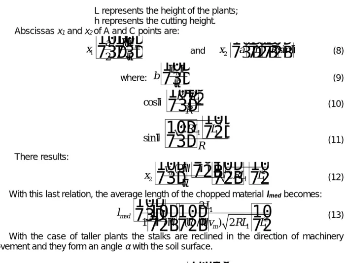
(7)L represents the height of the plants; h represents the cutting height. Abscissasx1andx2of A and C points are:
ma
x
2
1 and
x
2
a
b
R
sin
(8)where:
mb
(9)R
L
R
1cos
(10)R
L
RL
1 122
sin
(11)There results:
2
2 1 1
(2
)
2
m
v
x
RL
L
(12)With this last relation, the average length of the chopped material Imedbecomes:
1
2 1 1
2
1
/
( /
) 2
med
m
L
l
v
RL
L
(13)With the case of taller plants the stalks are reclined in the direction of machinery movement and they form an angleα with the soil surface.
E
H
Hs
tg
(14)where:His the cutting height
Hsis the height from soil of the shield for plant tilt
Eis the distance from the rotation axle of drum to the edge of the shield
Figure 5 – The completion of the cutting process with the case of tall plants
The maximum length of cutting is:
max
sin
/
cos
mR
v
l
(15)The average length of the cutting fragments l0 can be approximately considered as
given by the following relation:
0
2
cos
cos
m
v
a
l
(16)From the analysis of this formula there results that the lenght of cutting increases with the increasing of working speed of machinery vm and with the increasing of plants tilt (α angle). Characteristically for the cutting devices with jointed knives is the high variation of the cutting length and this fact does not recommend them for harvesting fodder crops for silo. Generally,, the uniformity of the length of cutting, with the case of herbaceous plants, is 20-45%.
RESULTS AND DISCUSSIONS
During the working process with the cutting machinery, the vegetal mass that will be chopped is not constant as flow volume on the whole length of the machinery passing. This mass varies in comparison with the normal flow volume Q by a certain value (±δQ). This variation of the flow volume influences the mechanical interaction between the vegetal mass that is subjected to chopping and the impeller of the machinery for chopping vegetal mass.
This way, for the same working regime that is characterized by λ (λ= Vp/Vm)
parameter, in heterogeneous vegetal mass condition, although the size of the cutting is the same, the consumed energy is different. As a result, the kinetic energy of the impeller varies. For the impeller to function a high influence is given by the inertial momentum of the impellerIzin relation with the rotation axle.
2
1 2
m
kg
r
m
I
n
i i i
z
(17)
where:
mi– the mass of a knife of the impeller (kg);
ri– the distance from the rotation axle of the impeller to the center of gravity of the
knife.
With the case of a feeding of the chopping impeller by a variable vegetal mass the inertial momentum of the impeller must be higher. In this situation, at a low value of the vegetal mass that enters into the chopping device, the kinetic energy of the impeller increases and decreases when the quantity that enters into the chopping device increases.
The kinetic energy at a certain moment is been given by the following relation:
2
2
z cI
k
E
(18)and the relation:
dt
d
I
dt
dE
k
c
z
2
2
şi
P
k
I
dt
dE
c z
(19)Express the variation of the kinetic energy of the impeller in function of time: In these relations, the signification of the symbols is the following:
ω– the angular speed of the rotor (rad/s);
ε– the angular acceleration for rotor when the feeding vegetal mass decreases or the surplus of power (rad/s2);
δP – the power surplus needed for the acceleration of the rotor when the feeding vegetal mass increases or the surplus of power.
1 2 2:
2
2
r
V
I
V
m
E
i i ic
2 2 22 2 2 2 2 2 2 2 2
1
2
1
1
2
2
2
2
2
r
I
I
I
I
I
m
E
i i (20)2
2
I
k
E
c
From these data we can conclude that the chopping device that have an uneven floe volume in a given time produces acceleration or a deceleration of the rotor with an acceleration whose expression is given by the next formula:
zI
P
K
(21)The (21) relation demonstrates that the mass that is subjected to chopping influences the degree of chopping.
The influence of the working speed on the chopping degree
The working process performed by the rotor of a machinery for chopping vegetal mass is a phenomenon that consists of the following phases: the entering of knives into the vegetal mass, cutting and taking the plants parts in rotation movement, hitting the cut plant parts by the counter knife or the framework followed by the supplementary cut of them and the spreading of the chopped plants parts on the soil. With the case of machineries of chopping vegetal mass with horizontal rotor the working process can be performed by cutting the plants from up to down or from down to up.
The main phases of the chopping process (the entering of the knives into the vegetal mass and cutting it) depend by the working kinematic regime of the knife.
During the work, the cutting edge of a knife can be seen as a point at the periphery of a circle that rolls on a horizontal plane. So to speak, a knife performs a rotation in relation with the axle of the rotor and a translation movement given by machinery. This way, the trajectory of a point from the knife is a cycloid (figure 6) whose equations are:
asin
r
x şi
y
r
a
cos
(22) After the value ofa / rratio there can be distinguished the following types ofcycloids:
- short cycloid, where a < r figure 6 b; - long cycloid, where a > r figure 6 c; - normal cycloid, where a = r figure 6 d.
Figure 6 – Diverse trajectories of a point from the knife in function of the the translation movement given by machinery
The knife enters into the vegetal mass performing the cutting and taking the cut material on a curve arch. In order to make a normal taking of cut material there is need that horizontal component of the absolute speed of the knife to be reversely positioned as compared with forward direction of movement of machinery in the contact point with the vegetal mass.
This condition imposes that the peripheral speedVpof the knife to be higher than
the movement speedVmof machinery, namely:
m
p
r
V
V
It means:1
m p
V
V
(23)The dimensions of chopped material made by the knife of rotor depend by the working widthb of the knife, by the depth of entering into the vegetal mass aand by the advance s of the rotor.
z
2
(24)where:zis the number of knives that work on the same zone (band).
The time for the rotor to move withψ0angle is marked with tand it has the following
expression:
z
t
2
(25)The equation that express the length made by machinery when the rotor is spin by anψangle formed by two knives that work on the same band, namely the advance sis:
z
r
r
V
z
V
z
V
t
V
s
p m m
m
2
2
2
(26)From (26) relation there results that by increasing the ratio λ (the lowering of the speed Vm or increasing the speed vp) the advance s is lowered and it determine a finer
chopping of the vegetal mass.
Because cutting is made on cycloid arches the inferior part, the stubble, has high increases of its heighth. Their height depends by s, respectively, λratio. By increasing the λ ratio the height of the crests decreases, resulting a even stubble. Nevertheless, with too high values of theλratio the energy consumption increases for chopping the same vegetal mass.
However, the increasing ofλratio involves the increasing of the peripheral speed of the knife, so, of the angular speed of rotor that has influence on the equilibrium of the rotor as well as on the increasing of the chopping degree.
BIBLIOGRAPHY
1. Caius Iacob, Mecanica teoretică, Editura didactică şi pedagogică, Bucureşti, 1980 2. Cândea I., Boboşilă M. şi colectiv, Mecanica-Cinematica. Editura Didactică şi Pedagogică, Bucureşti, 1998
3. Ganea I. - Maşini de tocat resturi vegetale de porumb şi floarea soarelui, ASAS, 1999. 4. Neculăiasa V., Dănilă I., - Procese de lucru şi maşini agricole de recoltat. Editura A. 92, Iaşi, 1995.
5. Popa E., - Maşina universală pentru tocarea retsurilor vegetale. Revista Mecanizarea Agriculturii nr. 4/1999.