Rtl Desing And Vlsi Implementation Of An Efficient Convolution
Encoder And Adaptive Viterbi Decoder
Thalakayala Eleesha #1 V.G.Pavan Kumar #2
#1 Student, M.Tech (VLSI), #2 Assistant Professor, Sri Vasavi Institute Of Engineering And Technology, Nandamuru.
Abstract:
Error-correcting convolution codes provide a proven method to limit the effects of noise in digital data communication. Convolution codes are employed to implement forward error correction (FEC) but the complexity of correspondingdecoder’s increases exponentially with the restraint length K. Sophistication Encoding with Viterbi decoding is a powerful FEC technique that is particularly suited to a channel in which the transmitted signal is corrupted mainly by Additive white Gaussian Noise. Here, we present a Convolution Encoder and Viterbi Decoder with a constraint length of 9 and code rate of 1/2. This is comprehended using Verilog HDL. It is simulated and synthesized using Modalism Altera 10.0d and Xilinx 12.1 ISE. The main goal of this paper is to design based Convolution Encoder and Viterbi Decoder which encodes/decodes the data. This architecture has simpler code and flexible configuration when compared to other architectures and saves silicon area through efficient device utilization which makes it favorable for fpga.
Key words: Error correction, Convolution codes, encoding, decoding.
I. Introduction
Convolution coding is a popular error-correcting coding mechanism used in digital transmissions. A message is elaborated, and then conveyed into a noisy channel. This convolution process encrypts some information into the transmitted signal, thereby raising the data capacity of the channel. The Viterbi algorithm is a popular mechanism used to decrypt convolution coded messages. The algorithm traces the most likely state sequences the encrypter went through in encoding the message, and exercises this communication to determine the original message. In its place of valuing a message based on each individual sample in the signal, the convolution encrypting and Viterbi decrypting process packages and encrypts a message as a series, delivering a level of correspondence between each sample in the signal. As the convolution codes are used mostly for the channel encrypting of data to achieve low-error-rate in latest
wireless communication standards like GSM, WCDMA and WLAN; the use of optimal decrypting Viterbi algorithm will suit. All communication channels are subject to the additive white Gaussian noise (AWGN) around the environment. The block codes can be applied only for the block of data whereas convolution coding has can be applied to a continuous data stream as well as to blocks of data. Convolution Encoding with Viterbi decoding is a powerful FEC technique that is particularly suited to a channel in which the transmitted signal is corrupted mainly by AWGN. It operates on data stream and has memory that uses previous bits to encrypt. It is not complex and has good performance with low implementation cost. The Viterbi algorithm (VA) was proposed in 1967 by Andrew Viterbi [1] and is used for decoding a bit stream that has been encoded using FEC.
II.Convolution Coding
Convolution coding has been used in communication systems including deep space communications and wireless communications. It offers an alternative to block codes for transmission over a noisy channel. An advantage of convolution coding is that it can be applied to a continuous data stream as well as to blocks of data.
Block diagram:
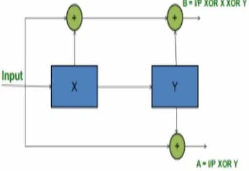
Figure 1: Block Diagram of Convolution Encoder
past. The set of past values of input data is called a state. The number of input data values used to generate the code is called the constraint length. Each set of outputs is generated by EX-OR ing a pattern of current and shifted values of input data. The pattern used to generate the coded output value can be expressed as binary strings called “Generator Polynomials” (GP). The MSB of the GP corresponds to the input; the LSBs of the GP correspond to the state. The encoder that has been designed is a linear, non–systematic, convolution encoder.
Truth Table:
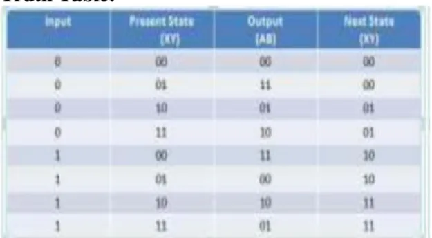
Figure 2 Truth Table of Convolution Encoder
The truth table for this encoder is shown in Fig 2.The present state values are the possible 2 bit combinations for both 0 and 1 input. The output AB is obtained from the expressions in the fig 1. Then, the next state values are calculated by right shifting the input and present state values together by 1 bit position.
III.Viterbi Decoder
Although convolution encoding is a simple procedure, decoding of a convolution code is much more complex task. Several classes of algorithms exist for this purpose:
Threshold decoding is the simplest of them, but it can be successfully applied only to the specific classes of convolution codes. It is also far from optimal.
Sequential decoding is a class of algorithms performing much better than threshold algorithms. Their serious advantage is that decoding complexity is virtually independent from the length of the particular code. Although sequential algorithms are also suboptimal, they are successfully used with very long codes, where no other algorithm can be acceptable. The main drawback of sequential decoding is unpredictable decoding latency.
Viterbi decoding is an optimal (in a maximum-likelihood sense) algorithm for decoding of a convolution code.
Its main drawback is that the decoding complexity grows exponentially with the code length. So, it can be utilized only for relatively short codes. [4]
The Viterbi algorithm works by forming trellis structure, which is eventually traced back for decoding the received information. It reduces the computational complexity by using simpler trellis structure. The Viterbi Decoder is used in many FEC applications and in systems where data are transmitted and subject to errors before reception.
Viterbi decoders also have the property of compressing the number of bits of the data input to half. As a result redundancy in the codes is also reduced. Hence Viterbi decoding is more effective and efficient. The Viterbi decoder designed here is 8:4 decoders. The same logic and concept can also be extended to further number of bits also. Viterbi decoders are based on the basic algorithm which comprises of minimum path and minimum distance calculation and retracing the path.
Block Diagram
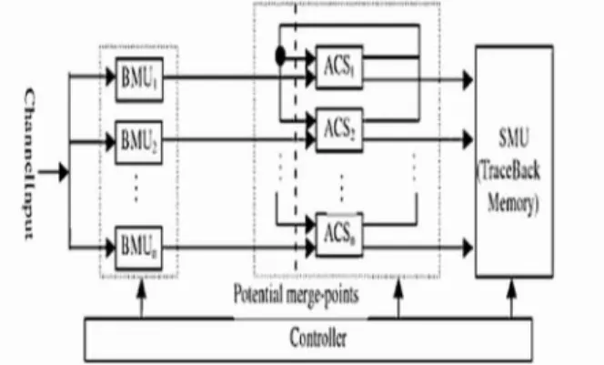
Figure 3: Block Diagram of Viterbi Decoder
The BMU (branch metric unit) receives input data from the channel and computes a metric for each state and input combination. The metric is the Hamming distance for hard-decision encoded data. The ACS (add compare- select) unit is the second functional unit of the Viterbi decoder. This is based on minimum distance calculations that are obtained from the previous row values. Trace-back unit restores an (almost) maximum likelihood path from the decisions made by BMU. This is the final stage of the Viterbi decoder where the input that was transmitted by using the convolution encoder is once again retrieved and the 4 bit message is obtained.
A. Viterbi algorithm:
well as least reserved decoding are generally similar in a defined binary symmetric channel. Kia, J. (2005, p.1) explains Viterbi algorithm as a “dynamic algorithm that uses certain path metrics to compute the most likely path of a transmitted sequence” [13]. The basic performance of the Viterbi decoder is analyzed with the block diagram shown below. It consists of three main blocks branch metric unit, add compare select and trace back unit. The unit of branch metric will calculate all the branch metrics and then processed to add compare for selecting the surviving branches as per the branch metrics finally the decoded data bits are generated by the trace back unit.
Figure 4: Shows the basic block diagram of Viterbi decoder.
The overall performance of the Viterbi algorithm is analyzed with the help of conventional codes. The simulated block diagram explains the operation of detecting and correcting the coding errors in normal communication system. The transmitted bits of data are encoded in the first block with conventional code that is (CC encoder) which are modulated by means of binary pulse-amplitude modulation (PAM) so as to tune those bits into antipodal bits and process to the additive white Gaussian noise (AWGN) channel thus obtained data combined with noise is supplied to soft decision Viterbi algorithm (SDVA) which only accepts the antipodal data at the input for decoding and produces the output decoded bits.
IV.Trellis Diagram
Trellis diagrams are messy but generally preferred over both the tree and the state diagrams because they represent linear time sequencing of events. The x-axis is discrete time and all possible states are shown on the y-axis.
We move horizontally through the trellis with the passage of time. Each transition means new bits have
arrived. The trellis diagram is drawn by lining up all the possible states (2L) in the vertical axis. Then we connect each state to the next state by the allowable codeword’s for that state. There are only two choices possible at each state. These are determined by the arrival of either a 0 or a 1 bit. The arrows show the input bit and the output bits are shown in parentheses. The arrows going upwards represent a 0 bit and going downwards represent a 1 bit. The trellis diagram is unique to each code, same as both the state and tree diagrams are. We can draw the trellis for as many periods as we want. Each period repeats the possible transitions. We always begin at state 00. Starting from here, the trellis expands and in L bits becomes fully populated such that all transitions are possible.
Figure 5: Viterbi algorithm trellis diagram
The transitions then repeat from this point on. The output of each transition is written on the line within brackets as shown. The state transitions for a given ‘1’ input are denoted by dotted lines while state transitions for a given ‘0’ input are denoted by solid lines.
Figure 6: A Trellis diagram
represented with a dot and the state transition is shown as edge of branch. Each and every branch is known as the branch metric as it is associated at Euclidean distance with the symbol towards final transition.
State Table:
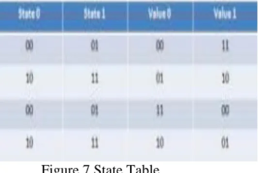
The State table is obtained from the code trellis. The arrows emanating from 00 and 01 present state end in
00. Hence we can divide into two states (00 in state 0 and 01 in state 1) and write the respective output values in
value 0 and value 1.Repeat the same for other states as well.
Figure 7 State Table
A. Example for convolution coding
Consider a 4 bit input to the convolution encoder 0101.The present state is buffer value 00.The output bits are obtained from the expressions according to below Fig.
Figure 8 Convolution Encoder Logic Examples
The next state is obtained by right shifting input and XY bits together. This becomes the present state for the next bit. In this way the output codeword is obtained. In this way the convolution encoder works and the 8-bit output codeword is obtained.
V.Softwares Used
Xilinx ISE is a software tool produced by Xilinx for synthesis and analysis of HDL designs,
which enables the developer to synthesize ("compile") their designs, perform timing analysis, examine RTL diagrams, simulate a design's reaction to different stimuli, and configure the target device with the programmer. This design is simulated using Modelsim Starter Edition and synthesized using Xilinx 10.1 ISE. Modelsim SE entry-level simulator, offers VHDL, Verilog, or mixed-language simulation.
1. Designing FPGA Devices with Verilog:
Verilog is popular for synthesis designs because: Verilog is less verbose than traditional VHDL. Verilog is standardized as IEEE-STD-1364-95 and IEEE-STD-1364-2001.
Since Verilog was not originally intended as an input to synthesis, many Verilog constructs are not supported by synthesis tools.
VI.Comparative Study A. Previous Architectures:
There are different approaches of implementation for Convolution Encoder and Viterbi Decoder in the literatures. A Viterbi decoder can be implemented using a DSP or as an ASIC [6]. Implementing the Viterbi decoder as an ASIC is more efficient in terms of power and performance. However, an ASIC is, for the most part, a fixed design, and does not allow for much operational flexibility. A DSP provides a large amount of operational flexibility but this is gained at the loss of performance and power efficiency. These Implementations have fixed constraint length and Code Rate or have partial configuration facility. In order to overcome the performance issue of
Convolution Encoder and Viterbi Decoder and have more flexible configuration, FPGA based implementation has been proposed. The advantages of the FPGA approach to DSP Implementation include higher sampling rates than are available from traditional DSP chips, lower costs than an ASIC. The FPGA also adds design flexibility and adaptability with optimal device utilization conserving both board space and system power that is often not the case with DSP chips. Below Table Comparative Study between different implementations
CORE ASIC DSP FPGA
Flexibility Not much Good Best Performance Better Good Best
Area used Good Good best
VII.Conclusion
This architecture has comparatively simpler code and flexible configuration when compared to other architectures and saves silicon area through efficient device utilization which makes it favorable for present day FPGA’s.Although this architecture has limitations because of the increasing number of computations in decoding performed at each stage which makes it impractical for convolution codes with large constraint length, it provides a good tradeoff between performance and area.
VIII.References
[1] Viterbi.A.J, "Convolution codes and their performance in communication systems," IEEE Transaction on Communications, vol.com-19, pp. 751 to 771, October 1971.
[2] Wong, Y., Jian, W., HuiChong, O., Kyun, C., Noordi, N. “Implementation of Convolutional Encoder and Viterbi Decoder using VHDL”, Proceedings of IEEE International conference on Research and Development Malaysia, November 2009.
[3] “A Viterbi Decoder Using System C for Area Efficient VLSI Implementation” Thesis by Serkan Sozen.
4] http://www.1-core.com
[5]http://www.xilinx.com/itp/xilinx10/books/docs/si m/sim.pdf
[6] Architectures for ASIC implementations of low-density parity-check convolutional encoders and decoders Swamy, Bates, et al. - 2005
[7]http://www.xilinx.com/support/documentation/sw _manuals/xilinx13_1/ug685.pdf
[8] Verilog HDL Synthesis A Practical primer By J. Bhaskar.
Authors:
Thalakayala Eleesha received his B.Tech degree in Electronics and Communication Engineering. from M.L ENGINEERING COLLEGE, singarayakonda, prakasam District, Andhra Pradesh, India, (2012). He is currently pursuing his M.Tech (VLSI System Design) from Sri Vasavi Institute of Engineering and Technology, Nandamuru. His current research interest includes in VLSI System Design.