GHEORGHE IOSIF1
1Universitaty of Craiova
Keywords: altitudes, geodesy
ABSTRACT
In order to understand the consequences of the parallel misalignment of the level surfaces for the geodetic work, we should take for instance the system of orthometric altitudes, in which the geoid is the reference surface and the othometric altitudes is the segment of force line caught between the position of the point, on the earth surface and respectively on the geoid.
1. CONSEQUENCES OF THE PARALLEL MISALIGNMENT OF THE EQUIPOTENTIAL SURFACE
In the ellipsoid geodesy, a system of altitudes is defined as follows: -by choosing a surface of reference;
-by adopting a definition with a physical or geometric meaning, throught which the position of the points on the surface of the Earth is described against the surface of refernce;
-by transforming the bench-marks, measured through the geometrical levelling, in the considered system of altitudes.
As known, the levelling surfaces are not parallel, hence in each point of space can be written:
gdh
dW
a formula that established the dependency between the distance dh and the potentail difference dW existent between two infinitely close levels.
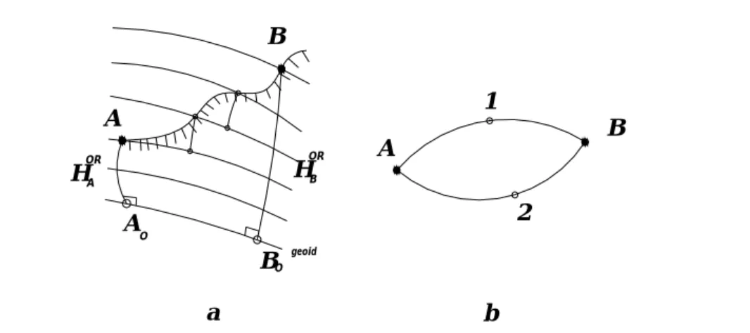
In order to understand the consequences of the parallel misalignment of the level surfaces for the geodetic work, we should take for instance the system of orthometric altitudes, in which the geoid is the reference surface and the othometric altitudes is the segment of force line caught between the position of the point, on the earth surface and respectively on the geoid.
On figure 1, we can see that the sum of the elementary levell differences, measured
on the lay-out between points A and B, noted
B
A
AB
h
A
B
HORA
OR HB
AO
BO geoid
A B
1
2
a b
Fig. 1. The consequences of the misalignment of the level surfaces on the level callibrations for lines and large syze polygons.
The orthometric altitudes of points A and B,are noted
H
Aor andH
Bor .Thus, it is shown how the result obtained directly throught the works of geometric
levelling
B
A
h
is in relation to the covered layout. The conclusion is in fig. 1 the sum ofthe elementary level diffrences, measured on layouts 1 and 2, which will not be equal to each other, not even in the ideal case of the perdected geodesic observations with no errors of measurement. In the formed polygon there will be a resulted unclosing, also calledfundamental error of the geometric geodetic levelling.
This is why in the works of geometric levell of superior order it is necessary to also conduct gravimetric analysis parallely in order to calculate the differences of potential.
2. THE SYSTEM OF DYNAMIC ALTITUDES
The notion of dynamic altitude has been introduces by Helmert in the year 1873. If we admit that we have a level line drawing from the fundamental zero point, to point P, where the level differences as well as the gravity acceleration has been measured, the difference CP between the potential of the geoid Wo, and the potential of the level surface
WPof the point P is called the geopotential number of point P.
The geopotential number can be determined throught conducting the two types of works:
-gravimetric works (g);
-geometrical levelling works (Δh).
The dynamic altitude is noted with Hd and is obtained through the division of the
geopotential number CP by a constant value, more precisely by the value of the normal
gravity, at the 45olatitude, in relation to the reference elipsoid:
o
y
C
H
D PP
45
The system of dynamic altitudes is characterised by a special property, i.e.: the points situated on a certain level surface have the same dynamic altitude.
The reference surface is the geoid with the known potential WO,and the dynamic
altitude of the point P (
H
PD) is defined by the above relation, where y45o is the normalgravity at the level of the elipsoid at latitude B=45O; y
by the formula:
h G
dh g
B A
B
A D
AB
O O
o o
45 45
45 45
The system of dynamic coordinates has been at the based of the creation of the level network in Western Europe.
4 The system of orthometric altitudes
Since the defition of the geopotential number does not depend on the used layout, it is supposed that the integration is conducted along the force line:
:
HPORO
P gdH
C ,
the definition of the orthometric altitude is: wheregrepresents the average of the gravity values along the force linePOPwhen a finite number of segments is considered.
5 The orthometric correction
The orthometric correction is added to the level difference measured directly in order to determine the orthometric level difference by the formula:
DR
A OR B D A OR B D AB OR
AB H H H H H
H
In order to calcualte the difference existent between the orthometric and the dynamic altitudes we imagine a geometric leveling layout going from point A0, along the
force line, up to mark A. It can be described as:
A
A
OR A H h
0
On the same layout
A
A
D A A D
A D
A H h
H
0
0
0
D A A OR A D
A H
H
0
or HORA HAD AD
0
and similarly HBOR HBD BDB
0
The dynamic corrections are calcualted by the known formulars.
The level differences from A to B are calculated by the formula or
ab ab ORr
AB h
H
where ABoOR represents the orthometric correction on the layout AB.
6 Helmert Altitude
H g
C
HH P
P
0424 . 0
where the numerator represents the
P or
P C
g
7 The ellipsoid orthometric altitude
Has been very used in the begining of geodesy when gravimetric measurements where not avalilable. If in the formula of the orthometric correction, we substitute g , we obtain the expression of the ellipsoid othometric correction:
B B
A A
B
A ORS
ab h H H
O O
o o
O O
45 45
45 45
45 45
8 The system of normal altitudes
The system of normal altitudes is currently being used in our country and it has been grounded by M. S. Molodenski in the year 1945.
Considering that by knowing the medium gravity g along the force line, Molodenski
suggest to use the normal gravity field instead of the real gravity field. The formula to calculate the normal altitude of a point P will be:
P N
P C
H
1
where
n H
n n dH
H 0
1
The level difference in the system of normal altitudes will be:
N AB AB N
A N B N
AB H H h
H
Where the correction in the system of normal altitudes is:
BA
ors AB n
AB h
g
o
45
CASE STUDY:
Determining the differences of altitudes in different systems.
Initial data:
- The latitude of bench 1 :B1=45O23`19444”
- The latitude of geodesic bench 2 :B2=45O24`166667”
- The approximate altitude of bench 1 : H*1=325.85 m - The gravity of bench 1 : g1=980615.62 mgal.
- The gravitaty of bench 2 : g2=980654.60 mgal.
- The measured diference of level: Δho12=16.7634 and γ45o=980617.6 mgal.
It is requested:
- The Diference of altitudes in the systems:
-dynamic;
-The Normal Gravity on the ellipsoid of the benchmarks 1 and 2
γ11980=978032.7 (1+0.00527904 sin2B1)= 980635.14 mgal.
γ21980=978032.7 (1+0.00527904 sin2B2)= 980636.01 mgal.
-The normal gravitaty at ground level
γ1H= γ11980-0.086 H*A= 980534.48 mgal.
γ2H= γ21980-0.086 H*A= 980530.28 mgal.
-The difference of altitude in the dynamic system
m hg
g o
ors
o o
0015 . 0 2
1
12 45 2 1
45
12
m hH12d 12o 12d 16.764
-The difference of altitude in the normal orthometric system
m HH
h O O
o o
H H
o ors
0003 . 0 2
2 2
1 *
2 45 2 2 * 1 45 1 1 12 45 2 1
45
12
m hH12ors 12o 12ors 16.7631
-The difference of altitude in the normal system
m orsd n
0012 . 0
12 12
12
m hH12n 12n 12o 16.7646
BIBLIOGRAPHY:
1. Ghiţău, Dumitru – Geodezie şi Gravimetrie geodezică, Editura Didactică şi Pedagogică, Bucureşti 1983
2. Moldoveanu, Constantin – Geodezie. Noţiuni de geodezie fizică şi elipsoidală, poziţionare, Editura MATRIXRom 2002
3. Păunescu, Cornel - Curs de Geodezie - Topografie, Editura Universităţii din Bucureşti, 2001