EY3600 CASE FBD User's Manual GZF 500
7000866003 P12
This description corresponds to the current program release, Version 5.0. Changes may occur at any time without prior notification.
1 General ... 9
1.1 Hardware and Software Requirements ... 9
2 CASE FBD Basic Functions... 11
2.1 Starting the Program... 12
2.2 Workbench... 13
2.2.1 Toolbar ... 14
2.2.2 Browser ... 15
2.3 Create an AS ... 17
2.3.1 AS Configuration (AutomationStation) ... 18
2.4 Create an AS Net... 19
2.4.1 Assign an AS to the AS Net ... 19
2.5 FBD Editor (FBD = Function Block Diagram) ... 20
2.5.1 Toolbar ... 21
2.5.2 Structuring Programs ... 22
2.5.3 Insert Blocks... 24
2.5.3.1 Overview Diagram ... 24
2.5.3.2 Function Chart ... 26
2.5.4 Move, Copy and Delete Blocks ... 28
2.5.5 Presentation of Blocks... 29
2.5.6 Block Properties (Property Sheet)... 29
2.5.6.1 Block Definition ... 30
2.5.6.2 Shown Connectors ... 31
2.5.6.3 Parameters ... 32
2.5.6.4 Inputs ... 32
2.5.6.5 Invert Connectors ... 33
2.5.7 Connections ... 34
2.5.7.1 Direct Connections between Blocks ... 34
2.5.7.2 Internal Edge Bar Connections... 37
2.5.7.3 Connections between Function Charts... 39
2.5.7.4 Modify Connectors ... 41
2.5.7.5 Remarks on Edge Connectors... 42
2.5.7.6 Connections between AS in the same Net ... 43
2.5.7.7 Connections via the COMMON ... 49
2.5.7.8 Connections between AS in another Net... 56
2.5.8 Load and Test the Program ... 59
2.5.8.1 Converting the FBD Program ... 59
2.5.8.2 Load Program into the AS ... 62
2.5.8.3 View Online... 64
3 Extended Functions ... 69
3.1 Workbench ... 69
3.1.1 File Menu ... 69
3.1.2 Edit Menu... 72
3.1.3 Browser Menu... 74
3.1.4 Administrator Menu... 80
3.1.5 Information Menu ... 82
3.1.6 View Menu ... 83
3.2 AutomationStation ... 84
3.2.1 File Menu ... 85
3.2.2 Edit Menu... 85
3.2.3 Program Menu ... 86
3.2.4 Special Menu ... 87
3.2.5 View Menu ... 87
3.3 FBD Editor ... 88
3.3.1 File Menu ... 88
3.3.2 Edit Menu... 90
3.3.3 Libraries Menu ... 92
3.3.4 View Menu ... 95
3.3.5 Insert Menu ... 96
3.3.6 Online Menu... 97
3.3.7 Special Menu ... 98
3.3.8 Window Menu ... 100
3.4 User Blocks ... 101
3.4.1 Create a User Block... 101
3.4.2 Apply User Blocks... 104
3.4.3 Edit User Blocks... 105
3.4.3.1 Change placed Blocks... 105
3.4.3.2 Change Library... 105
3.4.3.3 Delete User Blocks... 107
3.4.3.4 Edit Structure... 108
3.4.4 Export/Import User Blocks ... 109
3.4.5 User Plans ... 111
3.4.5.1 Create a User Plan... 111
3.4.5.2 Apply User Diagrams ... 112
3.4.5.3 Edit Library Structure... 112
3.4.5.4 Export/Import User Plans ... 113
3.5 Working with Templates and Libraries ... 114
3.6.1.1 Create User... 121
3.6.1.2 Change Groups and Users ... 122
3.6.2 Login... 123
3.6.3 User Import/Export (Security Depot) ... 123
3.6.3.1 Create a Security Depot ... 124
3.6.3.2 Link to existing Security Depot ... 125
3.7 House Addresses ... 128
3.7.1 Configuration of the House Address ... 128
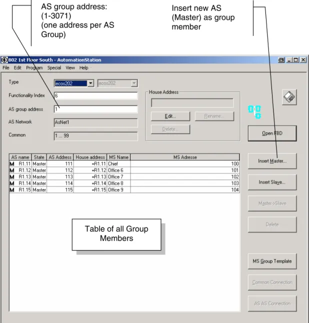
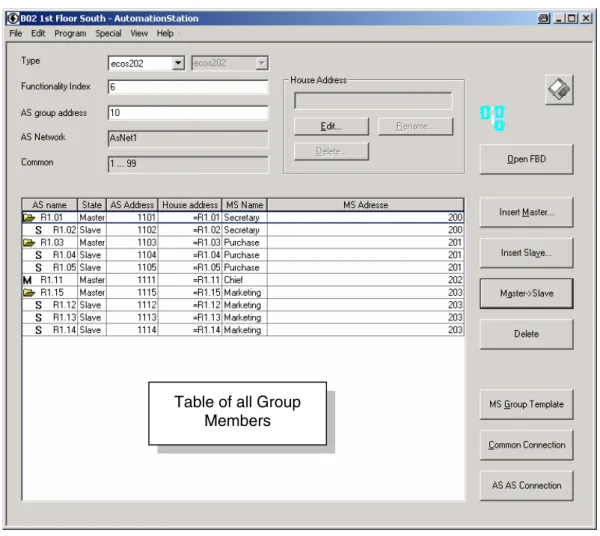
3.8 AS-Groups ... 131
3.8.1 Master/Slave-Group ... 134
3.8.2 Connections ... 136
3.8.2.1 Connections within the MS-Group ... 136
3.8.2.2 Connections to AS outside of the MS-Group... 137
3.8.3 House Addresses ... 140
3.8.3.1 Configuration... 141
3.9 Topology Wizard and Project Directory Structure ... 142
3.9.1 Create a new Project... 144
3.9.2 Edit or Add to an existing Project ... 151
3.9.2.1 Create a new complete Workbench (incl. PDBL) ... 153
3.9.2.2 Configure Connections ... 156
3.9.2.3 Create a new Workbench (and link with existing PDBL) ... 159
3.9.2.4 Edit the Project Topology... 161
4 System Handling ... 163
4.1 General ... 163
4.2 Project Database PDB... 165
4.3 Local Project Database PDBL ... 165
4.4 Synchronisation Mechanisms ... 166
4.4.1 Create new Object... 166
4.4.2 Borrow Mechanisms... 167
4.5 System Environment (*.dse) ... 168
4.6 Workbench... 169
4.7 Plant Device Table, BMT, BMTL ... 170
4.7.1 Synchronisation of House Addresses ... 171
4.7.2 Synchronisation of Objects in the DPE Browser... 171
4.7.3 Synchronisation of House Addresses (BmTConfig-Object) ... 172
4.7.4 Restrictions and Important Remarks... 173
4.8 Topology (*.ntp) ... 174
5.3 Select Documents ... 181
5.4 Select Printer... 187
5.5 List&Label Designer ... 188
List of icons and symbols
Keyboard operation
Wait
Diskette
Mouse operation
Single mouse click with left button
Single mouse click with right-hand button
Double mouse click with left button
Double mouse click with right-hand button
Description
Application
Information
Attention
Trademarks
Designer Trademark of Micrografx, Inc. Micrografx Designer Trademark of Micrografx, Inc. Media Manager Trademark of Micrografx, Inc. Windows Trademark of Microsoft Corporation Microsoft Office 97 Professional Trademark of Microsoft Corporation MS Office Trademark of Microsoft Corporation Microsoft Access 97 Trademark of Microsoft Corporation Microsoft Office 2000 Trademark of Microsoft Corporation Microsoft Word Trademark of Microsoft Corporation Acrobat Reader Adobe Systems Incorporated Pentium Trademark of Intel Corporation
1
General
The function block diagram editor tool, EY3600 CASE FBD, is used for graphic pro-gramming of automation stations such as EY3600 nova and EY3600 ecos.
It can be used to create function block diagrams and to parameterise stations. In addition, control technology procedures can be shown graphically so that they are easier to monitor.
The FBD programming is based on the IEC61131-3 standard, making it even easier to operate EY3600 CASE FBD, which is already simple to handle.
EY3600 CASE FBD is based on the Windows NT4, Windows 2000 and Windows XP operating systems from Microsoft.
1.1
Hardware and Software Requirements
The CASE FBD program requires the following PC hardware and software.
HW requirements:
PC:
Processor: INTEL Pentium II or higher
Working memory: Minimum 192 Mbytes (recommended: 256 Mbytes) Hard disk: min. 100 Mbytes (for programs, libraries and data) Diskette drive: Internal, 3½ " 1.44 Mbytes (to install the licence) CD-ROM drive: For the installation
Connections: 1 mouse
1 printer 1 network SW requirements:
Windows NT4.0 (SP6a), Win 2000, Win XP Microsoft Internet Explorer 4.01 or higher
Information
2
CASE FBD Basic Functions
You can use the CASE FBD Editor to create the installation-specific software for the automation stations within a project.
The automation station (AS) regulates, controls and monitors your installation with the program. The inputs and outputs are accessed via addresses.
CASE FBD Editor PC with
communication device
Automation station (AS)
Installation Control panel
(EYT240) novaNet
2.1
Starting the Program
The following conditions must be fulfilled:
• the licence must be installed
• the program must be installed
• a project must be set up
You will find the relevant information in the "First Steps" manual, 7 000931 003.
To enable the program to be loaded into an automation station and tested, the following additional conditions must also be fulfilled:
• AS with novaNet connection
• novaNet communication with card EYS290 or router EYZ291 The FBD Editor is opened with the Workbench (*.dew).
2.2
Workbench
The Workbench is the point of entry for users, and it provides a view (Browser) of the objects that are present in a project database (AS, AS nets, etc.). You start these ob-jects from the Workbench if (for example) you want to edit a function block diagram.
Thanks to the object-oriented operating philosophy, knowledge of a special command syntax is no longer necessary. Objects are represented on the user surface by graphic symbols (icons) which can be opened by menu commands or by clicking with the mouse.
When an object is opened, the appropriate software component is automatically called up to display or edit the content of the object.
In addition, other linked files and objects (such as a system environment, Autostart ob-jects, libraries etc.) are loaded when the Workbench is started.
You will see the following view:
Object browser
Properties window for marked folder or object.
Window with the files linked in the Work-bench
Menu bar Toolbar
Combo Box (navigation)
2.2.1
Toolbar
The toolbar for the Workbench shows these icons:
Icon Meaning
Save: saves the current configuration of the Workbench.
New folder: creates a new folder below the marked item.
New MDBO: creates a new object in the marked folder.
Copy: copies the marked object onto the clipboard (CTRL-C).
Paste: inserts the contents of the clipboard at the current position (CTRL-V).
Rename: gives the marked folder or object a new name.
2.2.2
Browser
The object browser shows you an Explorer view of the linked files and their content:
The properties window shows you the content of the marked folder and the relevant ob-ject properties:
System environment: contains the li-brary of firmware blocks, AS types and other necessary objects.
Project folder: your project data are stored here.
CasePrjLib: library with tem-plates and model solutions.
Object properties
Icon Meaning
Newly created object
Object published in the PDB or returned to the PDB. (present with write-protection in the PDBL)
Object borrowed in the current PDBL
Object borrowed in another PDBL
(present in the current PDBL with write protection)
Object no longer present in the PDB (deleted from another PDBL)
2.3
Create an AS
Open the project folder by double-clicking or clicking on the +.
Mark the folder "AS".
In the toolbar, press the icon for "new MDBO", or click "New DB Object" with the right-hand mouse button.
Enter a name for the AS in the next window.
"AutomationStation1" is offered as the default name. However, you are free to select any name (e.g. "AS 1")...
... A new AS object has been created in the folder "AS".
Then open "AS 1" in the browser by double-clicking on it.
The AS object type still has to be set.
Define the AS as a "Single AS"...
2.3.1
AS Configuration (AutomationStation)
In the Browser, open the AS by double-clicking on it. You will see the configuration of the AS in the AutomationStation window.
Type
The AS type and any variants are defined in these fields. Variants Meaning
Ilext AS with 256 addresses and 2048 poolmoves (model B, FI >4) 128 AS with 128 addresses and 1024 poolmoves (model A)
Functionality Index
This is where you enter the Functionality Index (FI) for the relevant microprogram which is located in the AS. The FI represents the current software release and it changes when the firmware block library has been changed or extended. The FI set here must not be higher than the one that is actually present in the AS.
Address
Enter the AS address in this input field.
The AS address is shown by the position of the DIP switches for the AS in question.
2.4
Create an AS Net
A project can consist of several physical nets (novaNet). For this reason, these nets have to be set up and the AS have to be assigned to the corresponding nets. Go to the Workbench and open the project folder. Mark the "AS Nets" folder.
In the toolbar, press the icon for "New MDBO", or click "New DB-Object" with the right-hand mouse button. In the next window, enter a name for the AS net.
"AsNet1" is offered as the default name. However, you are free to choose any name...
... A new AS net object has been created in the "AS Nets" folder.
2.4.1
Assign an AS to the AS Net
In the Browser, open the AS net by double-clicking on it...
... Press the "Add" button.
Select "AS 1" and delete the tick from "Com-mon".
This means that "AS 1" is physically assigned to the AS net "ASNet1"...
2.5
FBD Editor (FBD = Function Block
Dia-gram)
So that a function block diagram can be created, the relevant AS has to be opened first. In the Browser, open the AS that you want by double-clicking on it...
...Then, in the "AutomationStation" window, press the "Open FBD" button.
Then you will see this view:
Work surface Menu bar
Toolbar
Page number Information field
2.5.1
Toolbar
The toolbar of the FBD Editor shows these icons:
Symbol Meaning
Save copy: saves a copy of the whole FBD diagram in a file (*.fbd).
Print preview: shows the function block diagram in print preview.
Print: prints the active function block diagram.
Find: searches for the text indicated in the function block diagram.
Cut: cuts out marked objects and keeps them on the clipboard.
Copy: copies marked objects onto the clipboard (Ctrl+C).
Paste: inserts the contents of the clipboard at the current position (Ctrl+V).
Select AS: selects an AS for Online observation (AS groups).
Online observation: starts online mode to view the current values.
Online block: in online mode, shows all parameters and values for the marked block.
View level up: goes to the next level up.
Enlarge: enlarges the view by one zoom stage.
Zoom out: reduces the view by one zoom stage.
Insert function block: opens the block selection.
Single link: links the marked connections to each other.
Linking tool: switches the linking tool on/off.
2.5.2
Structuring Programs
When the FBD Editor is opened, you are in the overview diagram. This is the highest working level within the AS.
A program consists of several function charts which themselves are built up from func-tion blocks or other funcfunc-tion charts (extra levels).
The corresponding function block types are selected by the user and placed on the screen. Then, the connections are made. The function chart can be several pages in size (max. 15). You can use scrolling to view the whole diagram.
Every function chart (overview block) is saved with its name and - together with other function charts - it is part of an AS program.
The scope of the function blocks within a function chart is determined by the user. To improve structuring and clarity, circuits that are functionally related to one another are grouped together in one function chart.
Placing an overview block in the overview diagram will create a new (empty) function chart. The function blocks are placed within a function chart. By placing more overview blocks within the function chart, you can create extra levels. A maximum of 4 levels is possible.
Overview block (function chart)
Overview
dia-gram
Level 1
Level 2
Level 3
Level 4
Overview block Function block
By double-clicking on an overview block, you can open this function chart in an addi-tional window and this will move you one level down. To go to the next level up, use this icon:
Function chart 2 Function
2.5.3
Insert Blocks
2.5.3.1
Overview Diagram
In the overview diagram, you can insert a new block via the "Insert | Overview Block" menu item or by clicking with the right-hand mouse button on "Insert Overview Block".
You can then place the overview block on the overview diagram. Other block types are as follows:
Text blocks: you can use these to place text fields at any desired position in the FBD, for example to enter brief descriptions.
User Plan: you can use these to insert ready-made function charts from a library.
No function blocks (controllers, PLC connections, I/O blocks etc.) can be placed directly in the overview diagram.
The editing area consists of cells for blocks, and routing channels. It is not possible to place blocks on routing channels ("no parking" on the cursor). The grid can be shown or hidden using an icon.
Information
Cells for blocks
Routing channel
Text block
2.5.3.2
Function Chart
The FBDs are created from function blocks in the function chart. You use these function blocks to create the installation-specific software for the automation stations.
Open the function chart by double-clicking on the overview block. The function chart will open in an extra window. For information purposes, the AS name, the function chart name and the level are shown in the title bar of the window.
In the function chart, you can insert a text block or an overview block (extra level) via the "Insert | Text Block/Overview Block" menu item or with a right-hand mouse-click on "Insert Text Block/Overview Block".
Overview block
Function chart
or a right-hand mouse click on "Insert Function Block" to insert a new function block....
...Then you will see the block selection window.
The block selection offers 4 main libraries to choose from:
Firmware: this library contains all the firm-ware blocks created by Sauter.
Users, National, International: these li-braries contain user blocks. User blocks make it possible to store frequently used circuits as blocks.
Open the "Firmware" library and mark the category you want (e.g. Logic)...
... Mark the block you want (e.g. AND) and press "OK"....
... The block can now be placed on the function chart. ("Insert" appears on the cur-sor). You cannot place blocks on routing channels ("No parking" on the cursor).
For a multiple selection, drag the block onto the function chart with the left-hand mouse button pressed down. The "Block Selection" window stays open.
2.5.4
Move, Copy and Delete Blocks
Move
Each block can be moved after it has been placed. Mark the block, and drag it to the new destination with the left-hand mouse button pressed down ("Move" appears on the cursor) and then release the left-hand mouse button. You can also move several blocks at the same time. Use the left-hand mouse button to mark a group of blocks by putting a frame around them, and then drag them to the new destination with the left-hand mouse button pressed down.
Copy
Mark the block, press the right-hand mouse button and press "Copy" in the context menu. Move the cursor to the destination, press the right-hand mouse button and select "Paste". You can also copy several blocks at the same time. Use the left-hand mouse button to mark a group of blocks by putting a frame around them, press the right-hand mouse button, and press "Copy" (Ctrl+C). Move the cursor to the destination, press the right-hand mouse button and select "Paste" (Ctrl+V). If the Ctrl key is pressed in, you can also select single blocks only.
Delete
Mark a block by single-clicking on it, press the right-hand mouse button and click on "Delete" in the menu. You can also mark and delete several blocks. Existing connec-tions will also be deleted.
Caution: no extra enquiry is made before the deletion!
Use the Cut, Copy and Paste buttons as well.
2.5.5
Presentation of Blocks
The presentation of the blocks is based on standard IEC 1131-3. Each blocks has the following presentation properties:
2.5.6
Block Properties (Property Sheet)
The Property Sheet (block properties) contains:
the firmware block definition
the shown connectors
the parameters
the inputs (definition)
The respective properties are different for each block and they depend on its functional-ity. A detailed description of the firmware blocks is given in the "Firmware blocks" man-ual, 7 000877 003.
Mark the relevant block and press the right-hand mouse button....
.... Select "Properties" from the con-text menu. Note Block type Block number MFA (address) Connectors (output) Connectors (input) Comment Block symbol
open.
2.5.6.1
Block Definition
The following properties are available in the "Block definition" tab:
Comment You can enter a comment here that will be shown under the block. This entry is optional.
MFA Entering the MFA (address) is mandatory for input and output blocks so that the block is connected to the plant device (terminal). For all other firmware blocks, the MFA is automatically assigned by the FBD Editor on conversion.
House Address It is only possible to enter a house address for input/output blocks and software addresses. This entry is required if the datapoint is to be visualised (control panel, SCADA systems, etc.). The house ad-dresses are normally generated in CASE Prj and are automatically entered in the block, or are then available in the plant device table (BMT). Use the "Select" button to select a house address and as-sign it to the block. To enter the house address manually, use the "Edit" button. Existing house addresses can be renamed and de-leted.
2.5.6.2
Shown Connectors
The "Shown Connectors" tab shows all the available connectors (inputs and outputs) for blocks and their meanings.
Use the "None" button to hide all connectors, and use the "All" button to show all con-nectors for the block. By marking single concon-nectors (with a tick), you can make an indi-vidual selection. In the "Description" field, you can see a brief description of each con-nector. If "Use As Standard Layout" is enabled, the selection you have made will be used as the default the next time you call up the block.
Linked connectors cannot be hidden.
Information
Connectors (inputs)
Connectors (outputs)
2.5.6.3
Parameters
All the necessary internal parameters for a block are set in the "Parameters" tab. Pa-rameters are fixed values and they cannot be influenced externally.
Parameters that have been adjusted or entered must be set with the "Accept" button. Use the "Reset" button to reset the parameter in question to the default value. Use the "Download" button to transfer only the relevant block (values from "Parameters" and "Inputs") to the AS (Download single block).
2.5.6.4
Inputs
The "Input" tab is used to set all the other parameters for a block. Unlike "Parameters", each input is also present as a block connector here, so it can be influenced by appro-priate linking. If an input is linked, the value set in the Property Sheet will be overwritten in the AS.
the Property Sheet is closed with the "OK" button....
... The settings are accepted by the block.
2.5.6.5
Invert Connectors
Block connectors with a signal width of 1 bit (flags) can also be inverted (negated) di-rectly on the block. This is done in the Property Sheet for the connector in question.
Mark the connector you want by double-clicking with the left-hand mouse button....
... Then press the right-hand mouse button and select "Properties" from the context menu.
The Property Sheet for the connector will open....
... Enable the "Invert Connector" checkbox and press the "OK" button.
The connector is inverted.
2.5.7
Connections
There are basically two different types of connections:
connections within an AS
connections between different AS
For connections within an AS, these distinctions are made:
direct connections between blocks
internal edge connector connections within a function chart
connections between function charts
For connections between different AS, these distinctions are made:
connections between AS in the same net
connections via the COMMON
connections between AS in another net (DP-Router)
2.5.7.1
Direct Connections between Blocks
Connections between blocks can only be created with signal widths of the same type (Bit, Byte, DWord, Real32). The FBD Editor prevents the connection of signals of differ-ent types. If connections with differdiffer-ent signals are marked, the linking tool remains inac-tive.
Mark the connections you want to link....
... In the toolbar, you will now see the symbol for the single link....
... Press the" Single link" but-ton.
The connection between the blocks has been created. Connections are automatically routed in the routing channels and they cannot be changed.
Press the icon for "Linking tool"...
.... Create the connections be-tween the blocks by clicking on the connectors you want to link. (SourceÆ Destination 1 Æ Des-tination 2 etc.).
You are not allowed to connect an input more than once.
Information
Multiple connection
Delete Connections
If connectors are marked, you can use the DEL key to delete the relevant links between the connectors.
Depending on which connector is marked, several connectors can also be deleted.
DEL
DEL Marked connector
Marked connector
2.5.7.2
Internal Edge Bar Connections
If signals are used several times in the same function chart or over several pages, these signals can be linked via the edge bar. The connections made in this way can be used at any point via the left edge bar.
By double-clicking on the edge connector, you can open the edge bar dialogue...
.... Give the connection any name you want (Identifier)...
.... Then press the "OK" button.
Next, create a link from the block connec-tor to the edge connecconnec-tor.
By double-clicking on the edge connector, you can open the edge bar dialogue...
.... You can mark the signal you want in the "Internal Connection" window.
.... Then press the "OK" button.
Internal edge bar connections are identified by a transparent triangle.
Then create a link from the block connec-tor to the edge connecconnec-tor.
2.5.7.3
Connections between Function Charts
The procedure described in the previous section can be used for connections within a function chart. Of course, connections between different function charts (overview blocks) can also be created.
Variant 1
Open the edge bar dialogue by double-clicking on the edge con-nector ...
.... Give the connection any name you want (Identifier)...
.... Mark "Interface"
.... Then press the "OK" button.
Next, create a link from the block con-nector to the edge concon-nector.
Interfaces are identified by a black trian-gle.
Use this icon to move to the next level up (overview diagram).
The interface appears in the overview block as a new connector.
create an interface connector on the left-hand edge bar.
Then go to the next level up again.
The second interface has also been created.
You can now link the two con-nectors to one another.
Variant 2
The second method of making connections between function charts starts from the overview diagram (or the next level up).
Go to the overview diagram.
Link the free output connector with the free input connector of the two overview blocks.
The interfaces are automatically created and the identifier is automatically entered as a con-secutive number.
Then go to the function chart (by double-clicking on the overview block).
Of course, the identifiers can be renamed at a later stage and the edge connector can be moved to the appropriate position.
2.5.7.4
Modify Connectors
Existing edge connectors can also be modified.
Open the edge bar dialogue by double-clicking on an existing edge connector.
Delete Connection Undoes and deletes an existing connection.
If this action is performed on a connector on the right-hand side (source connector), all associated destina-tion connecdestina-tions are deleted. If the acdestina-tion is per-formed on a connector on the left-hand side (destina-tion connector), only the connec(destina-tion in ques(destina-tion is deleted.
Rename Connection Existing edge connectors can be renamed.
Reset Undoes and deletes an existing connection. See also "Delete Connection".
2.5.7.5
Remarks on Edge Connectors
An edge bar connection can be used several times as a destination (several identical connectors on the left-hand edge bar).
Connections between blocks via edge connectors can only be created with signal widths of the same type (Bit, Byte, DWord, Real32).
Move the mouse pointer onto a edge connec-tor. As a tool tip, you will see a
cross-reference to the connection. Information:
Page number, Block type + number, Connec-tor name
If several destinations are present, they are listed below each other.
Each edge connector can be moved after it has been placed. Mark the connector, keep the left-hand mouse button pressed in and drag it to the new destination ("Move" will appear on the cursor). Then release the left-hand mouse button.
Edge connectors can also be copied. Use the left-hand mouse key to mark a group of blocks and the edge bar by framing them. Use "Copy" and "Paste" to copy blocks and edge connectors (left and right sides). With the CTRL key pressed in, you can also select individual blocks or edge connectors only.
If a connector is defined as an interface, it cannot be used as an internal connection at the same time. Create a second edge con-nector as an internal connection.
2.5.7.6
Connections between AS in the same Net
The AS enables you to send information (e.g. a measured value) to another AS. This can be done with a targeted AS-AS connection or with a connection to the COMMON.
With a targeted connection, the measurement that is linked to AS 1 (source) is only
transmitted to AS 2 (destination).
The requirement for an AS-AS connection is that both AS are set up in the Workbench (source and destination) and both are assigned to the same net.
AS 3
AS 1
AS 2 Measurement
tion from the firmware block to the edge bar as "Interface".
You must use an EM... connector on the firmware block.
You can only use blocks in the "In-puts/Outputs" and "Software Addresses" categories.
Also check the block parameters (Threshold width TRW, Transmission priority TgP), so that spontaneous transmission functions correctly.
Use this icon to go to the overview diagram.
In the overview diagram, dou-ble-click on the edge connector to open the edge bar dialogue... .... Give the connection any name you want (Identifier)... .... Mark "Interface"
.... Then press the "OK" button.
Next, create a link from the overview block to the edge connector.
The interface is identified by a green lozenge.
Open a function chart...
... Place an EM_.. block ("Transfer" cate-gory).
This block is used as a container for exter-nal connections. The output can be linked to other blocks...
... Create an edge connector as "Interface" and link the connector to the block.
Use this icon to go to the overview diagram.
In the overview diagram, open the edge bar dialogue by double-clicking on the edge connector...
... In the "External Connection" section, press the "AS" button.
... Open the source AS by double-clicking on it (AS 1).
You will now see an overview of all objects and the pages used that are located in the overview diagram of the source AS... ... Double-click to open the page which con-tains the connector in the source AS.
Next, you will see an overview of all connec-tors made previously with an interface on the relevant page of the overview diagram... ... Mark the connector you want (no double-clicking)...
nector dialogue...
... Press the "OK" button.
The AS-AS connection has been created. The interface is now identified by a blue lozenge.
Next, make the link from the edge connec-tor to the relevant function chart.
In the source AS (AS 1), the connector is also marked with a blue lozenge in the overview diagram.
of an AS-AS connection.
Open the edge bar dialogue in the overview diagram by double-clicking on the edge con-nector.
In the "External Connection" section, you will see the associated AS-AS connection. Information:
AS net; AS; Connector
Use the "Delete Connection" button to delete an existing connection.
After creating new AS-AS connections, carry out a download on both automation stations (sequence: 1. destination AS, 2. source AS).
The information for an AS-AS connection is stored in the source AS (destination AS;MFA;DW).
2.5.7.7
Connections via the COMMON
A connection via the COMMON is used to transmit information from one AS to all AS located in the same net (broadcast). A total of 1984 COMMON variables are available for each AS net.
A connection onto the COMMON is used to transmit the measurement linked to AS 1 (source) to all AS (destination).
Open the AS net in the Workbench by double-clicking on it.
AS 3
AS 1
AS 2 Measurement
"Add" button, or....
.... mark an existing AS and press the "Change" button.
Tick the checkbox for "Assign COMMON Range"...
... Give a start and finish address for the COMMON range. This continuous range specifies the number and range of the addresses that can be described by the AS.
... Now press the "OK" button
Only one address range (for description) can be specified for each AS.
The range cannot overlap.
If possible, keep intervals between the AS or reserve addresses free, so that exten-sions can be implemented.
For each AS net, a total of 1984 COMMON addresses are available.
range can be seen in the upper win-dow.
The lower window contains the symbol table. A symbolic address (variable) can be assigned here to every COMMON address (1-1984) . This makes it much easier to select an address in the FBD Editor.
Press the "Add" button.
First select the AS that you want...
... In the "Address" box, enter the address of the COMMON cell and in the
"COMMON Name" box, enter the associ-ated variable name.
Press the "Accept" button to go to the next free address or press the "OK" button to finish.
The defined variables are now pre-sent in the "Symbol table" window. The COMMON variables are identi-fied by a prefixed % character.
Close the window when you have made all the assignments.
Remark:
You can also add more AS or COMMON variables at a later stage.
... Open a function chart.
In the source AS (AS 1), create a connec-tion from the firmware block to the edge bar as "Interface".
You must use an EM... connector on the firmware block.
You can only use blocks in the "In-puts/Outputs" and "Software Addresses" categories.
Also check the block parameters (Threshold width TRW, Transmission priority TgP), so that spontaneous transmission functions correctly.
Use this icon to go to the overview diagram.
In the overview diagram, open the edge bar dialogue by double-clicking on the edge connector...
... In the "External Connection" section, press the "COMMON" button.
selection list. Remark:
You will see all the COMMON variables defined for this AS.
Press the "OK" button.
The COMMON variable is then entered in the edge connector dialogue...
... Press the "OK" button.
Next, create a link from the overview block to the edge connector.
... Place an "EM_.." block ("Transfer" category).
This block is used as a container for ex-ternal connections. The output can be linked to other blocks...
... Create an edge connector as "Inter-face" and link the connector to the block.
Use this icon to go to the overview diagram.
In the overview diagram, open the edge bar dialogue by dou-ble-clicking on the edge connec-tor...
... In the "External Connection" section, press the "COMMON" button.
In the selection list, you will see all the defined COMMON variables for this AS net to choose from...
... Select the variable you want and press the "OK" button.
edge connector dialogue...
... Press the "OK" button.
Die COMMON connection has been cre-ated.
Next, create the link from the edge connec-tor to the relevant function chart.
2.5.7.8
Connections between AS in another Net
A connection to an AS in another net (remote connection) is only possible with the help of the Datapoint Router EYL230 F020 or with suitable management software. Please see the relevant description concerning the procedure for using suitable management software.
Preparation:
The internal AS net connections that are used as the signal source are transferred to the DP router as an AS-AS connection or as a COMMON connection.
In the following example, 2 signals are transmitted from AS net 1(ASNet1) to AS net 2 (ASNet2). The two signals are transmitted as a COMMON connection to DPRouter1.
Create an AS of type DPRouter (DPRouter1) and assign it to a net (ASNet1).
Create a second AS of type DPRouter (DPRouter2) and assign it to the other net (ASNet2).
Create the internal net connections for the two DPRouters as an AS-AS connection or as a COMMON con-nection.
Then open AS "DPRouter1" and open the FBD Editor. On the overview diagram, create the COMMON connection to the edge bar.
ASNet 2
two firmware blocks of type "DPR_Send".
In this example, an analogue value is transmitted with block
DPR_Send_AI and a binary value (Bit 31) is transmitted with block DPR_Send_BI.
Assign an MFA to the blocks.
In the overview diagram, create the links from the edge connectors to the overview blocks.
Then open AS "DPRouter2" and open the FBD Editor.
Open an overview block and place a "DPR_Rec_AI" firmware block and a "DPR_Rec_BI" firmware block. Assign an MFA to the blocks.
Important:
The MFA source Æ destination must match!
Link the blocks with the edge con-nectors. Use the EM... connectors for this.
links from the overview block to the edge connectors.
The link to the edge bar can either be made as an AS-AS connection (interface) or as a COMMON con-nection.
Also check the block parameters (Threshold width TRW, Transmission priority TgP), so that spontaneous transmission functions correctly.
This completes the remote connection between 2 AS nets. The addresses can now be used as targeted AS-AS connections or in the whole net as COMMON variables.
A DPRouter can be used as a transmission and receive station (bidirectional).
Attention
2.5.8
Load and Test the Program
After the program has been set up graphically with the FBD Editor, it must be translated into "AS machine language" and loaded into the AS.
2.5.8.1
Converting the FBD Program
Converting involves translating the graphic program into AS machine language. In addi-tion, an MFA is assigned to the blocks (exception: for hardware input/output blocks, the user must set the MFA).
Conversion of the function block diagram into instructions and assignment of the MFA are based on the position of the block in the function chart (left to right, top to bottom).
In the AS, the instructions are written to an Instruction List and they are worked through in a serial sequence (one after another). The mode of working is also cyclical, meaning that the program will be continuously repeated. The placement of the blocks and hence the sequence of the instructions can be especially important for functions which have to be worked through in the same work cycle (time-critical PLC functions).
Example 1:
In the circuit in Example 1, the AND function (3) is worked through last. This means that the result of the AND function is only present at the OR block (2) one work cycle later.
1 2 3 4
5 6
7 8
1 3
On the other hand, if the circuit is structured as in Example 2, the blocks are worked through in a serial sequence (one after another). The result of the AND function (1) therefore undergoes further processing in the OR block (2) during the same work cycle.
The same rules must also be followed for placing overview blocks.
Firstly, the overview block DI (1) is worked through in full. Then, the overview block PLC-1 (2) is worked through completely, followed by overview block DO (3). At the end of the cycle, the overview block PLC-2 (4) is dealt with. The outputs from overview block PLC-2 are therefore only processed one cycle later in overview block DO.
The sequence of the blocks requires particular attention for applications with short reac-tion times, such as light and blind controls. The number of instrucreac-tions does not influ-ence the length of the cycle time (approx. 0.5 sec.).
1 2 3
1 2
gram | Conversion" menu item.
You will see a progress indicator during the con-version.
A successful conversion will then be indicated in a window.
You are also given information about the pool moves needed (instructions).
If errors occurred during the conversion, a win-dow tells you about this...
... Press the "OK" button.
You will then see a list of errors...
... Mark the error and press the "Display" button. Then you will be taken to the relevant block in the function chart.
2.5.8.2
Load Program into the AS
First check that the connections for the novaNet and the communication device (EYS290, EYZ291) settings are correct.
Start the download with the "File | Pro-gram | Download" menu item.
If any changes have been made to the FBD program, a conversion is carried out auto-matically before the download.
Remark
AS Initialisation With this option, the AS is initialised before the download. The initialisation deletes the entire RAM content of the AS. Select this option if you are using a new microprogram, for example.
Reset Counters With this option, all the volume counters are set to zero (re-set). If you do not choose this option, the current meter val-ues are retained (on initialisation as well).
Reset HRC and Tt With this option, all the hours run counters (HRC) and totali-sations (Tt) are set to zero (reset). If you do not choose this option, the current meter values are retained (on initialisation as well).
Time Programs With this option, the time program created from novaPro32 is sent to the AS. If you do not choose this option, the time pro-gram set in the AS is retained.
Calendar With this option, the calendar created from novaPro32 is sent to the AS. If you do not choose this option, the calendar set in the AS is retained.
XS/L With this option, the setpoint values (XS) and limit values (L) set in the FBD are sent to the AS. If you do not choose this option, the setpoint and limit values for the I/O-Blocks set in the AS are retained.
This option only relates to I/O-Blocks.
FBD Program With this option, the actual program is sent to the AS.
Increased Download Message Priority
With this option, the download is executed with message priority 9, thus with higher priority than the spontaneous re-sponses from the AS to the PC (MP 8). If you do not choose this option, the download is executed with message priority 5. Select the options you want and press the "OK" button.
Problems with communication or other error messages are shown in a window.
You will see a message when the download is finished...
... Press "OK".
2.5.8.3
View Online
After the download has been completed, you can view the signals online in the FBD. Press the "Online obser-vation" icon.
After a short while, the values will appear as blue numerals in the connectors of the blocks.
In ONLINE mode, you can also view the values of single blocks in detail.
Switch to online mode and select the relevant block with the left-hand mouse button. Then press the "Online block" icon.
In the "Single Block Detail Online" window, you can view all the values and parameters for the block. Close the window with the "Termi-nate Monitoring" button.
2.5.9
Backing up FBD Programs
2.5.9.1
Save Program
An FBD program is saved automatically when the FBD Editor is closed via the "File | Close" menu item or with the "Close" button.
In this case, the program is saved in the PDBL when the FBD Editor is closed.
This window shows the saving procedure. The window closes automatically as soon as the save has ended.
The AutomationStation window must not be closed while this window is shown.
2.5.9.2
Export Programs
An FBD program can be exported to a file (*.fbd) with a name defined by the user. It is advisable to use this function regularly while working with the FBD Editor. If you choose a new name for each copy, you can refer back to various created versions.
A file of this sort can of course be imported into an AS as well.
In the FBD Editor, "File" menu, select the "Program | Export" function.
You will also find the same function in the "Auto-mationStation" window with the "Program | Export" menu item.
Select the file directory and give the file any name you like.
Press the "Save" button.
2.5.9.3
Import Programs
In the "AutomationStation" window, select the "Program | Import" menu item...
...or, in the FBD Editor, "File" menu, select the "Program | Import" function.
Select the file you want to import and press the "Open" button.
The function block diagram will then be im-ported.
The import includes the transfer of all block parameters except for house addresses. Of course, the function block diagram can then be opened and edited further.
When an import takes place, the entire content of the existing AS is overwritten. Any function charts for the AS which already exist will be lost.
Refer to Section 3.5.1, "Use Solutions from completed Projects", if you only want to im-port parts of a function block diagram.
3
Extended Functions
3.1
Workbench
3.1.1
File Menu
New
Creates a new Workbench. However, do not use this menu item if you want to create a new Workbench. Use the Topology Wizard to create a new Workbench (see Section 3.9.2.3, "Create a new Workbench (and link with existing PDBL)").
Open
Opens an existing Workbench. First, this closes all linked files in the background before the selected Workbench is started. The function can also be used on an inter-project basis.
Save
Saves the active configuration.
Save as
Saves the active configuration under a new name. Enter the new filename.
Properties
Opens the settings for the active Work-bench.
The properties can be set in the following dialogue.
The Workbench then has to be saved if the properties are to be changed perma-nently.
Save password Saves the password for the active log-in. With this setting, you can switch off the password request when the Workbench is started.
Backup options Shows the documents which are monitored by the integrated backup functionality. Use the "Add" button to add new OLE objects. Use the "Delete" button to delete a marked document. For backup, only use documents "AsNet Document" (AS net) and "AStatn Document" (AS).
Change Password
You can use this menu item to change the password for the active user. The new password is saved in the active System Environment (*.dse).
Log In (Change)
You can use this function to temporarily change the active user (Log In). The Workbench must then be saved if the properties are to be changed permanently.
Close
3.1.2
Edit Menu
New Browser
Opens a new Browser in an extra window.
New PDBL Link
You can use this function to link and start an extra PDBL.
Use this function, for example, if you want to link the library PDBL
(CasePrjLib_XXXXXX.lpf) with the current project.
The extra PDBL that has been linked is shown in the Workbench.
Then you can open the objects and copy them into the active project.
Additionally, you can link a PDBL for another project in the current project.
It is not allowed to link more than one PDBL of the same project.
The link is saved automatically in the settings for the Workbench. Use the "Delete" menu item to undo a link.
See also Section 3.5, "Working with Templates and Libraries".
Delete
This function deletes the marked entry or the marked link.
Mark an entry in the window. Then select the "Delete" function and the link will be deleted.
Delete all Browser
Deletes all additional Browsers.
An additional Browser is shown in the Workbench by a "Browser" entry.
Update Security Depot Link
Use this function to register the link to the security depot (see also Section 3.6.3, "User Import/Export (Security Depot)".
Use this function if you have set up a cen-tral security depot and a conflict is shown in the Workbench.
Only PDBL Use this function if a conflict is shown under "PDBL Security".
3.1.3
Browser Menu
New Folder
Creates a new folder under the mark.
New DB Object
Creates a new object in the marked folder.
In the "AS" folder, you can only create AutomationStation objects and in the "AS nets" folder , you can only create ASNet objects.
You can create any objects you like (Word, Excel objects etc.) in the "User Data" folder.
Users must not create any objects in any of the other folders.
Open Object
Opens (starts) the marked object (by double-clicking)
Copy
Copies the marked object to the clipboard (CTRL-C).
Paste
Inserts the clipboard contents at the current position (CTRL-V)
Rename
Gives the marked folder or object a new name.
Synchronisation
Use this menu item to carry out the various synchronisation operations between the PDB and the PDBL. The selection is valid for the marked folder or the marked object. Multiple selection of objects is possible.
You can also access the menu items with the right-hand mouse button.
Read Reads the current status from the PDB into the PDBL. Borrowed objects are not overwritten.
Borrow Borrows the object to the PDBL. The object is blocked in the PDB.
Return Returns the object to the PDB. The object is write-protected in the PDBL.
Publish This publishes and enters a newly created object in the PDB. The object is write-protected in the PDBL and must be borrowed out again for further editing.
Delete locally Deletes an object locally in the PDBL. Cannot be per-formed on borrowed objects.
Delete completely Deletes an object in the PDB and the PDBL. Objects not yet published in the PDB (newly created ones) must be deleted with this function.
Forced Return This enables an object to be returned to the PDB by an-other user. The user requires administrator rights for this function.
Forced Return unchanged This enables changes to be cancelled by another user. The user requires administrator rights for this function. See also Section 4.4, "Synchronisation Mechanisms".
Properties
Shows the properties of the marked object.
The properties in this window are only in-tended for internal purposes.
The most important object properties for the user are shown for each object in the Browser.
Security
Shows the rights that are valid for this object, for each user group.
Use the "Take ownership" button to transfer the object to the logged-in user. (Only possi-ble for objects that have not yet been pub-lished in the PDB).
Use the "Add" button to add user groups or individual users for the marked object (see also Section 3.6, "User Administration").
Options
Shows the options for the properties window of the Browser.
At "Display columns" you can activate or deactivate the columns you want.
At "MDBO double click mode", you can set the op-tions that are valid for double-clicking on an object. Enable "MDBO open" so that an object (AS, AS nets) is started by double-clicking on it.
Expand
Shows the content of the marked folder or the marked object.
Insert in Autostart
Inserts the selected object into the Autostart group. Use the Update Tool to update exist-ing projects.
Backup
You can use the integrated backup function to prevent it becoming impossible to read data after a PC crash. In the Workbench properties, you set the documents that are to be monitored by the backup (see also Section 3.1.1, "File Menu").
The actions monitored in the backup are saved in a file with ending *.lbk.
If a backup exists, you will receive a message to this effect when you start the Workbench.
The project starts in a special backup mode, and only the object relating to the backup is shown in the Browser(e.g. an AS).
Then you can select the vari-ous options in the "Backup" menu item.
Display Original Use this function to open and check the object with the original content (when the crash occurred).
Display Backup Use this function to open and check the object with backup content (when you start up).
Use Original Use this function to retain the original status and use it when you next start up.
You can only select the "Use original" or "Use backup" option once for an object and it is irrevocable.
As long as no option is selected ("Use original" or "Use backup"), the Workbench will always start in backup mode.
Then close the Workbench. When you next start up, the project will have normal status again.
Update
Updates the Browser view.
Update (with PDB)
Reads the content of the selected folder from the PDB. Unlike the "Synchronisation | Read" function, only the objects and object properties are updated (update table of con-tents) and no data are transferred into the PDBL.
3.1.4
Administrator Menu
User Accounts
Users' access to objects can be restricted. Administration is handled on the basis of users and user groups. As the default, 3 user groups and 4 users are set up. User administration is described in detail in Section 3.6, "User Administration".
Change PDB Path
The path to the respective PDB is saved in the PDBL and it can be seen in the links window of the Workbench. You can change the path to the PDB. This may be necessary if the project is no longer present in the original directory structure.
In the links window, mark the PDBL and select the "Change PDB Path" function. In the next window, you can select the PDB.
Security Depot
You can use this menu item to adjust the setting for the central security depot. The functions of the security depot are described in detail in Section 3.6.3, "User Import/Export (Security Depot)".
Defragment Data Base
When objects are deleted, the database file size is not reduced. To release this memory space again and to reduce the file size accordingly, the databases must be defrag-mented.
Mark the database you want (PDBL, DSE) in the Work-bench and then select the op-tion you want.
Selected Defragments the marked database (PDBL or DSE)
Corresponding Defragments the associated PDB
All Defragments the PDBL and the associated PDB
The original database is then backed up with the "*.bak" ending and a defragmentation is performed. The Workbench has to be restarted after this.
3.1.5
Information Menu
Borrowed Objects
This menu item shows all borrowed objects. The display corresponds to the display in the Browser.
Objects borrowed by this User
This menu item shows all the objects borrowed by the selected user.
Autostart Objects
You can use this menu item to check the Autostart objects that are linked in this Workbench.
Use the "Remove" button to delete a marked entry.
The objects are normally added automatically using the Topology Wizard!
Missing Autostart objects in existing projects should be updated with the Update Tool.
3.1.6
View Menu
You can use this menu item to change the Workbench view.
Toolbar Shows or hides the toolbar.
Status Bar Shows or hides the status bar.
Combo Box Shows or hides the Combo box.
3.2
AutomationStation
If an AS is opened in the Workbench, you will then be shown the "AutomationStation" window. The hardware configuration for the AS is set in this window.
Type
Use these boxes to define the AS type and any variants. Variants Meaning
Ilext AS with 256 addresses and 2048 poolmoves (model B, FI >4) 128 AS with 128 addresses and 1024 poolmoves (model A)
Functionality Index
This is where you enter the Functionality Index (FI) for the relevant microprogram which is located in the AS. The FI represents the current software status and it changes if the firmware block library has been changed or extended. The FI set here must not be higher than the one which is actually present in the AS.
Address
Enter the AS address in this input box. The AS address can be seen from the DIP switches of the AS in question.
AS Network
The associated AS net is entered in this box.
Common
In this box, the COMMON range that has been assigned for this AS is entered.
House Address
Use this box to enter the house address of the AS. To enter the house address, use the "Edit" button. Existing house addresses can be renamed and deleted.
"Open FBD" button
Use this button to open the FBD Editor for this AS.
"Disk symbol" button
Use this button to save the current datafile in the PDBL.
Carry out regular interim saves when you are working in the FBD Editor.
3.2.1
File Menu
Update
Updates the display in the window.
Export
Exports the AS including program content as a file (*.ast). Use the "Program | Export" function to create a backup copy.
Close
Closes the dialogue and returns to the Workbench. At the same time, the data are writ-ten to the PDBL.
3.2.2
Edit Menu
Read AS type and FI
Reads the AS type and the Functionality Index from the AS. You must first enter the relevant AS address in the "Address" field.
The information that is read will automatically be entered in the relevant fields.
3.2.3
Program Menu
Export
Exports the FBD program to a file (*.fbd).
This function can be used to create a backup copy of the FBD program.
See also Section 2.5.9.2, "Export Programs".
Import
Imports a program from a file (*.fbd).
When the import is performed, the existing content of the FBD program is overwritten.
See also Section 2.5.9.3, "Import Programs".
Conversion
Converting involves translating the graphic program into AS machine language. An MFA is also assigned to the blocks.
The functions are described in detail in Section 2.5.8, "Load and Test the Program".
Download
A download writes the converted program to the AS.
The functions are described in detail in Section 2.5.8, "Load and Test the Program".
Upload
An upload enables current setpoint values and limit values from I/O blocks to be read from the AS. The read values are saved in the FBD and are then visible in the relevant blocks.
User EPROM
You can create a binary file (*.bin) directly from the datafile.
A USER-EPROM can then be created from this binary file.
3.2.4
Special Menu
AS-Network Connection Refresh
Updates the data for the connections to the AS net (only for troubleshooting).
Language Selection
This selection is used to set the language for the control panel EYT240; it is written to the AS when a download is performed.
Update BMTL
Use this menu item to check the BMTL for er-rors and to compare it with the current datafile. Any conflicts are listed in a window.
3.2.5
View Menu
Use this menu item to change the AutomationStation view.
Toolbar Shows or hides the toolbar.
3.3
FBD Editor
3.3.1
File Menu
Close Program
Closes the active documents.
Program
Export Exports the FBD program to a file (*.fbd).
This function can be used to create a backup copy of the FBD program (complete AS).
Import Imports a program from a file (*.fbd).
When the import is performed, the entire content of the existing FBD program is overwritten (complete AS).
Conversion Converting involves translating the graphic program into AS machine language. An MFA is also assigned to the blocks. The functions are described in detail in Section 2.5.8, "Load and Test the Program"
Download A download writes the converted program to the AS.
The functions are described in detail in Section 2.5.8, "Load and Test the Program".
Upload An upload enables current setpoint values and limit values from I/O blocks to be read from the AS. The read values are saved in the FBD and are then visible in the relevant blocks.
User EPROM You can create a binary file (*.bin) directly from the datafile. A USER-EPROM can then be created from this binary file.
New Function Chart
Use this menu item to create a new function chart in the current AS, in the overview dia-gram (new overview block). You can enter a function chart name in the window.
Open Function Chart
You are shown a list of all overview blocks (function charts) for the current AS. You can open a chart directly if you select the corresponding entry from the list and press the "OK" button.
Delete Function Chart
You are shown a list of all overview blocks (function charts) for the current AS. You can delete charts by selecting the corre-sponding entry in the list and pressing the "Delete" button. After confirming with the "OK" button, the diagrams will be deleted.
Rename Function Chart
You are shown a list of all overview blocks (function charts) for the current AS. You can rename a chart by selecting the corre-sponding entry in the list and pressing the "Rename" button. The new name can then be entered in the window.