1
1
Overview
The TW6S is an all-in-one controller that integrates sending card functions with video processing. Designed with powerful video processing capability, it supports 7 video inputs and 6 Gigabit Ethernet outputs.
Based on the powerful FPGA processing platform, the TW6S supports multiple transition effects, such as quick seamless switching and fade, providing flexible display controlling and outstanding video presentations. The TW6S is equipped with an expansion card which can connect a USB drive to play the media files stored in it. By connecting a mouse and monitor, the USB playback can be intuitively monitored in real -time.
2
2
Appearance
2.1 Appearance
Front Panel
No. Button Function
1 ON/OFF Power button button
2 OLED screen Displays the current status and setting menu of the device. 3 Knob l On the home screen, pressing the knob enters the
operation menu screen.
l On the operation menu screen, rotating the knob selects
a menu item, and pressing the knob confirms the selection or enters the submenu
l When a menu item with parameters is selected, you can
rotate the knob to adjust the parameters. Please note that after adjustment, you need to press the knob again to confirm the adjustment.
3
5
Window control
Pressing a button enters the corresponding window property menu.
buttons Statuses of button indicators:
l On: The window is open.
l Off: The window is closed.
l Flashing: The window is being edited.
l When a window is open, holding down the window
button can close the window.
l In the USB playback mode, you can play, pause, play
previous, play next or stop current playback.
l SCALE:This is a shortcut button for auto fit function. You
can press this button to make the window of the lowest priority fit the screen.
6 Input source Pressing the button switches the input source for the buttons window. The button indicators indicate the statuses of the
input source.
Button indicator descriptions:
l Always on: he signal source is accessed.
l Flashing: he input source is in use, but no signal source
is accessed.
l Off: The input source is not in use and no signal source
is accessed.
7 Function l TAKE:In the switcher mode, pressing the TAKE button
buttons
can switch the PVW to PGM seamlessly with the transition effect set previously.
l FN:Custom menu button. In USB playback mode, press
the button to play the media files in USB drive.
8 USB l USB (Type-B): Connects to the upper computer.
USB (Type-A): A reserved port
Rear Panel
Input
Connector Quantity Description
3G-SDI 2 l Supports input resolutions up to1920×1080@60Hz
and downward compatibility.
l Supports both progressive and interlaced signals. l SDI1 supports de-interlacing.3G-SDI loop output
4
USB 2.0 2 Connects to a mouse/keyboard, or connects to a USB drive to play media files stored in the drive. The supported USB drives and the formats of the media files in it are described as follows.
l USB drive: FAT/FAT32
The USB drive cannot be a partitioned one or used as the system startup disk.
l Picture file format: JPG, JPEG, BMP, PNG and
WEBP
l Video file format: MP4, AVI, MKV, MOV, 3GP, FLV and MPG
Video coding: MPEG-1/2, MPEG-4 H.264/AVC, MVC, H.265/HEVC, H.263, GOOGLE VP8, VC-1 and MOTION JPEG
l Audio file format: MP3, WMA, WAV and 3GP
Audio coding:
− MPEG Audio: MPEG1/2/2.5 Audio Layer1/2/3
− Windows Media Audio: WMA Version4/4.1/7/8/9,
wmapro
− WAV Audio: MS-ADPCM, IMA-ADPCM, PCM
− FLAC Audio: Compress Level 0-8
− AAC Audio: ADIF,ATDS Header AAC-LC and
AAC-HE, AAC-ELD
− AMR Audio: AMR-NB, AMR-WB
DVI 2 l VESA standard
Supports input resolutions up to 1920×1200@60Hz and downward compatibility.
l Supports HDCP.
l Supports only progressive signals.
DVI LOOP 1 DVI loop output connector
HDMI 2 l Supports input resolutions up to 1920×1200@60Hz
and downward compatibility.
l Supports HDCP.
l Supports only progressive signals.
Output
Connector Quantity Description
Ethernet 6 6 Ethernet outputs
DVI 1 A monitoring connector, which can be set to preview the editing image or monitor the PGM
5
Control
Connector Quantity Description
ETHERNET 1 Connects to the PC for communication, or to the network.
USB (Type-B) 1 l Connects to the PC for device control. l Used as the input port for cascading devices
USB (Type-A) 1 Used as the output port for cascading devices
Model Type -L
-K
- L: 2 × 3G-SDI , 2 × HDMI 1.3, 2 × DVI, 1 × DVI+DVI LOOP and 1 × USB playback.
- K: 2 x CVBS, 1xDP, 1xHDMI , 2 × DVI, 1 × DVI+DVI LOOP and 1 × USB playback.
2.2 Applications
Note:
6
2.3 Home Screen
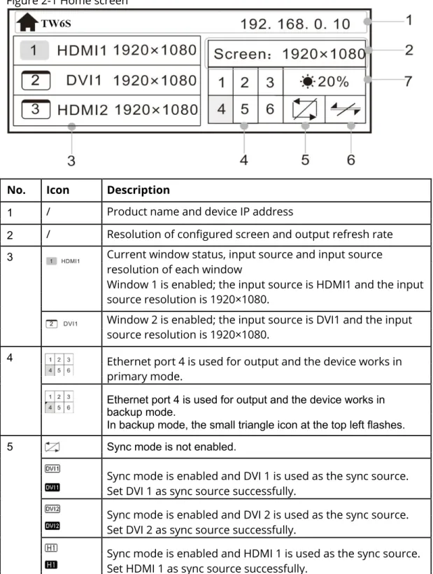
After the TW6S is powered on, the home screen is shown in the figure below.
Figure 2-1 Home screen
No. Icon Description
1 / Product name and device IP address
2 / Resolution of configured screen and output refresh rate 3 Current window status, input source and input source
resolution of each window
Window 1 is enabled; the input source is HDMI1 and the input source resolution is 1920×1080.
Window 2 is enabled; the input source is DVI1 and the input source resolution is 1920×1080.
4 Ethernet port 4 is used for output and the device works in
primary mode.
Ethernet port 4 is used for output and the device works in backup mode.
In backup mode, the small triangle icon at the top left flashes. 5 Sync mode is not enabled.
Sync mode is enabled and DVI 1 is used as the sync source. Set DVI 1 as sync source successfully.
Sync mode is enabled and DVI 2 is used as the sync source. Set DVI 2 as sync source successfully.
Sync mode is enabled and HDMI 1 is used as the sync source. Set HDMI 1 as sync source successfully.
7
Sync mode is enabled and HDMI 2 is used as the sync source. Set HDMI 2 as sync source successfully.
Sync mode is enabled and SDI 1 is used as the sync source. Set SDI 1 as sync source successfully.
Sync mode is enabled and SDI 2 is used as the sync source. Set SDI 2 as sync source successfully.
6 The device is not connected to the control computer.
The device is connected to the control computer via USB port. The device is connected to the control computer via Ethernet port.
7 LED screen brightness
Other l Hold down the knob and ESC button simultaneously to lock
or unlock all the buttons.
l If the icon appears on the home screen, all the buttons
are locked currently and cannot be operated. All the buttons are unlocked.
8
3
Menu Operations
The TW6S has powerful functions and is easy to operate. By using the knob and ESC button, you can perform any operations. Besides, you can switch the input sources by pressing only one button.
3.1 Operation Instructions
Knob
l On the home screen, pressing the knob enters the operation menu screen. l Onthe operation menu screen, rotating the knob selects a menu item,
and pressing the knob confirms the selection or enters the submenu.
l Whena menu item with parameters is selected, you can rotate the knob to
adjust the parameters. Please note that after adjustment, you need to press the knob again to confirm the adjustment.
ESC
This is a return button used to exit current menu or operation.
Button Locking and Unlocking
Hold down the knob and ESC button simultaneously for 3s or longer to lock or unlock all the buttons.
3.2 Screen Brightness
This function is used to adjust the LED display brightness.
On the home screen, press the knob to enter the menu. Then, rotate the knob to select Screen Brightness and press the knob to enter the brightness adjustment status. At last, rotate the knob to adjust the brightness value. After you set the brightness value, press the knob to confirm it.
9
Figure 3-1 Screen brightness
3.3 Screen Settings
3.3.1 Quick Configuration
Prerequisites
l TheLED screen is a regular one, not an irregular one.
l Thecabinets of the LED screen are regular, and each cabinet has the
same resolution.
l Thecabinet connection (data flow) must be one of the following 8 patterns.
The physical connection of cabinets loaded by each Ethernet port must be along the same direction.
l Duringdata flow settings, ensure that the Ethernet port 1 is at the
beginning position of the whole physical connection and the ports must be connected in order.
Operating Procedure
Step 1 Power on the LED screen.
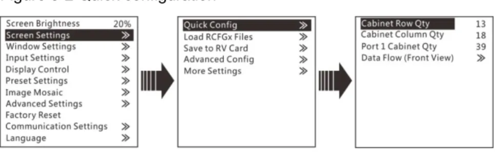
Step 2 On the menu page, choose Screen Settings > Quick Config to enter the
QuickConfig page.
Step 3 Set Cabinet Row Qty and Cabinet Column Qty (number of cabinet rows and columns) based on actual conditions of the LED screen.
10
Figure 3-2 Quick configuration
Step 4 Rotate the knob to select Port 1 Cabinet Qty (number of cabinets loaded by Ethernet port 1) and set the number of cabinets.
Note:
The number of cabinets loaded by Ethernet port should follow the rules below. Ethernet port 1 ≥ Ethernet port 2 ≥ Ethernet port 3 ≥ Ethernet port 4 ≥
Ethernet port 5 ≥ Ethernet port 6
The number of cabinets loaded by each Ethernet port must be the integral multiple of the number of cabinet rows or columns in the LED screen.
Step 5 Rotate the knob to select Data Flow (Front View) and press the knob to select one data flow according to current cabinet connection.
When setting the data flow, you can view the results of different data flow patterns in real time on LED display by rotating the knob. When you are
satisfied with the LED display image in which no image parts are overlapped or displayed repeatedly, press the knob to apply and save the selected data flow. If you press the ESC button, you will exit current operation and the data flow in preview will not be saved.
Figure 3-3 Data flow
3.3.2 Loading RCFGx Files
After the LED screen is powered on, if a certain cabinet or the entire LED screen cannot be lit, you can load the receiving card configuration files (namely RCFGx files) that have been configured
11
Step 3 Review the configuration file name and click Save the Change to HW to save the configuration file to the TW6S.
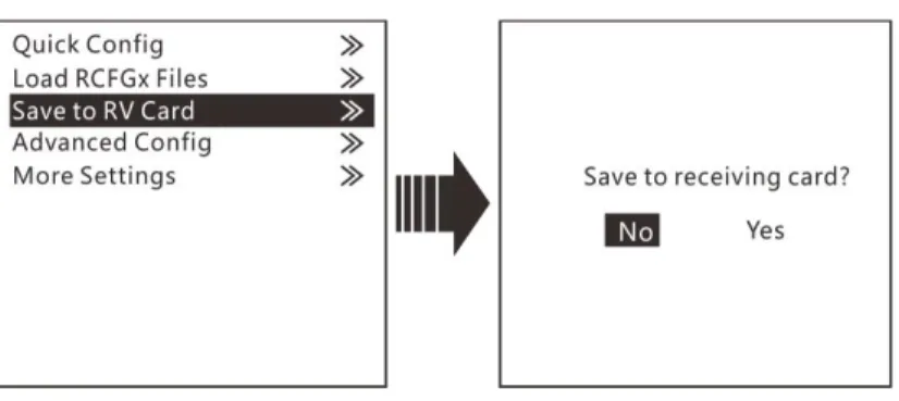
3.3.3 Saving to RV Card
After the cabinet configuration file is loaded or the receiving card color is changed, if you save the configuration data to receiving card by using the Save to RV Card function, the configuration data will not be lost even if power failure occurred.
12
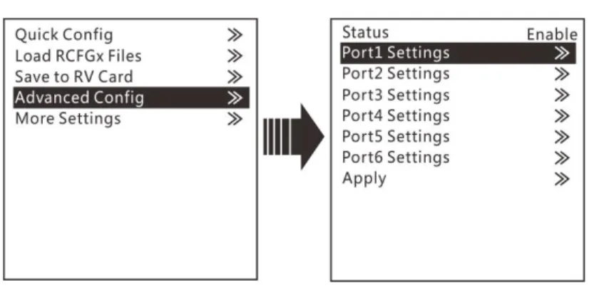
3.3.4 Advanced Configuration
The connection of cabinets loaded by each Ethernet port must follow the 8 data flow patterns provided in the TW6S.
In advanced configuration, you must manually set the Cabinet Row Qty,
CabinetColumn Qty, Horizontal Offset, Vertical Offset and Data Flow for each Ethernetport. It is recommended that you use this function under guidance of technical personnel.
Figure 3-8 Advanced configuration
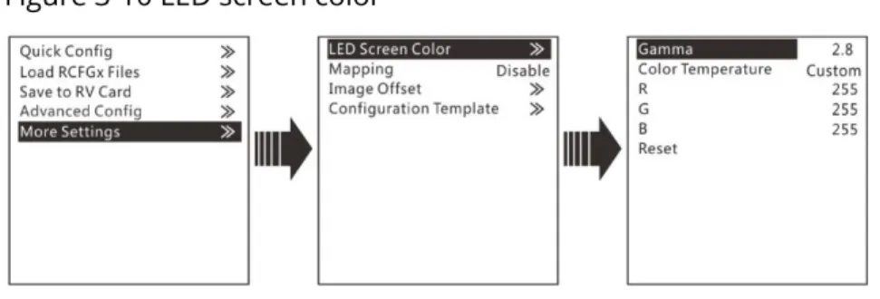
3.3.5 More Settings
You can set the LED screen color, image offset, configuration template and cabinet mapping information.
Figure 3-9 More settings
LED Screen Color
You can adjust the color (namely image quality) of the images displayed on the screen, including Gamma, color temperature, red/green/blue brightness (R/G/B), and reset the image quality to the default values.
13
Figure 3-10 LED screen color
Mapping
When the Mapping function is enabled, each cabinet's receiving card No. and Ethernet port information will be displayed on the LED display, which makes it convenient to check the cabinet information.
Image Offset
You can adjust the position of the image displayed on the screen, including its horizontal start position and vertical start position.
Figure 3-11 Image offset
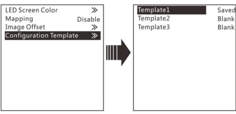
Configuration Template
The TW6S supports configuring 3 templates of screen configuration. After the screen is configured, save the configuration parameters as a configuration
template. The screen configuration parameters can be directly applied by choosing a template.
14
Figure 3-12 Configuration template
3.4 Window Settings
The TW6S supports up to 3 windows. The input source, size, position, priority and input cropping of each window can be set.
Window Settings
Step 1 Rotate the knob to select Window1 Setting, and press the knob to enter the submenu.
Step 2 Rotate the knob to select a parameter item you want to adjust and press the knob to enter the parameter adjustment status. Then, rotate the knob to adjust the parameter value. At last, press the knob again to confirm the parameter value.
l Window1 State: The status of current window
l Input Source: The input source used by current window l H Width: The number of pixels in the horizontal direction l Height: The number of pixels in the vertical direction l Initial X: The initial horizontal coordinate of the window
l Initial Y: The initial vertical coordinate of the window
l Priority: The displaying order of the window
l Input Crop: The function of cropping the input source and displaying the
cropped input source on current window Figure 3-13 Window settings
15
Scale
This function can make the window image fill the entire LED screen.
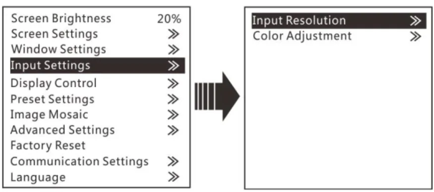
3.5 Input Settings
The resolutions of input sources can be changed on the TW6S. Currently, only HDMI and DVI connectors support the input resolution settings. To change the resolutions of other connectors, the only way is to change the output
resolutions on the front -end devices.
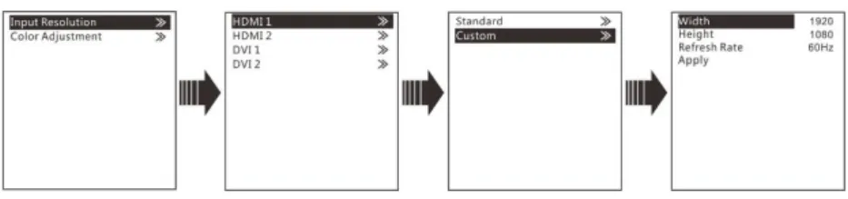
3.5.1 Input Resolution
The input resolution can be set through either of the following ways. Choosing a standard resolution
Customizing a resolution
Figure 3-14 Setting input resolution
Standard Resolution
The refresh rate of standard resolutions defaults to 60 Hz. If you want to change the refresh rate, go to the Custom menu.
Standard resolutions: 800×600, 1024×768, 1280×720, 1280×768, 1280×800,
1280×1024, 1366×768, 1440×900, 1600×1200, 1680×1050, 1920×1080, 1920×1200.
16
Custom Resolution
Rotate the knob to set a custom width (increasing by even numbers), height and refresh rate. After setting these parameters, rotate the knob to select
Apply and press the knob to apply the settings. If you do not press the knob to apply the settings, the custom resolution will not take effect.
Figure 3-16 Custom resolution
3.5.2 Color Adjustment
The TW6S supports adjustment of the input color (namely image quality), including brightness, contrast, saturation, hue and red/green/blue brightness (R/G/B).
Step 1 Choose Color Adjustment > HDMI 1 to enter the color adjustment page of HDMI 1 input source.
Step 2 Rotate the knob to select a parameter item you want to adjust and press the knob to
TWT
enter the parameter adjustment status. Then, rotate the knob to adjust the parameter
value. At last, press the knob again to confirm the adjustment.
l Brightness: The brightness of the input source
l Contrast: The ratio of the luminance of the brightest color (white) to that
of the darkest color (black)
l Saturation: The degree of how deep or how light the colors of the input
source image is
l Hue: The category of the colors of the input source image, namely red,
green and blue
l : The color cast of input source images. When the red parameter value is
greater, the image color is redder. The G and B have the same meaning.
l Reset: Reset all parameters in the input color adjustment menu to the
original default values. Figure 3-17 Adjusting input color
17
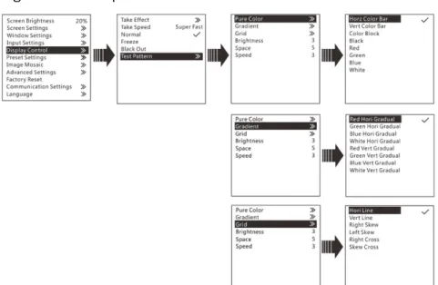
3.6 Display Control
This function is used to control the display. You can set the display to go black, display a test pattern, or go to normal display. You can also set the Take effect and Take speed.
Figure 3-18 Display control
l Take Effect: The transition effects of sending PVW image to PGM. There are
22effects in total, such as cut, fade, wipe from top, wipe from bottom, etc.
l Take Speed: The speed of transition effects. The range is 0.5s to 2s. l Normal: The LED screen displays the content of current input source
normally.
l Freeze:The current frame is frozen and always displayed.
l Black Out: The screen goes black and does not display the content. l Test Pattern: There are 22 test patterns in total, including pure colors,
gradientsand grids. You can adjust the brightness, space and speed of the test pattern based on test needs.
18
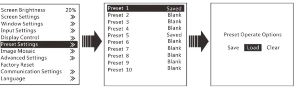
3.7 Preset Settings
The TW6S supports 16 user presets. After the preset data is configured, you can load and use the configured presets by pressing the number buttons on device front panel directly.
Step 1 On the main menu screen, rotate the knob to select Preset Settings.
Step 2 Rotate and press the knob to select a preset. Then rotate the knob to select
Save to save the settings to the selected preset.
Step 3 You can load a preset through either of the following ways.
− Rotate the knob to Load and press the knob to load the selected preset. − Press the number button on the device front panel to load a preset. −
Figure 3-20 Preset settings
3.8 Image Mosaic
When the pixel count of the LED screen is larger than the loading capacity of a single TW6S unit, the image mosaic function is required. The total loading capacity of all cascaded TW6S units should be greater than or equal to the total pixel count of the LED screen. The options are Disable, Equal and Unequal.
l Disable
Disable the image mosaic function.
l Equal
The areas loaded by all TW6S units are the same. You need to set the total H pixels, total V pixels, row quantity, column quantity and current load area position.
l Unequal
The areas loaded by all TW6S units are not the same. You need to set the total H pixels, total V pixels, load area width, load area height, as well as the start X and Y of the load area.
Note:
When the image mosaic function is enabled, Scale function will be disabled
automatically.
When HDMI or SDI input source is used for image mosaic, it is suggested you use
19
When the image mosaic function is enabled, it is suggested you select the
current playback source as the sync source.
Example:
The total pixels of the LED screen is 3000×2000, which exceeds the loading capacity of a single TW6S unit. You can use two TW6S units for image mosaic. The connection is shown as below.
Figure 3-21 Hardware connection for image mosaic
The parameter settings for Equal and Unequal are shown in the below table.
Equal
TW6S 1 TW6S 2 Total Width Pixels 3000
Total Height Pixels 2000 Mosaic Row Qty 16 Mosaic Column Qty 24
Load Area Position 1 2
Unequal
TW6S 1 TW6S 2 Total Width Pixels 3000
20
Unequal Total Height Pixels 2000
Load Area Width 1500 1500 Load Area Height 2000 2000 Load Area Start X 0 1500 Load Area Start Y 0 0
3.9 Advanced Settings
The advanced settings include system mode, video sync mode, Fn settings, redundancy, monitor resolution, advanced properties, factory reset and hardware version, as shown in the figure below.
Figure 3-22 Advanced settings
System Mode
You can set the system mode of TW6S here, including switcher and direct modes.
21
l Switcher: Monitor the image being edited. The edited image is displayed
on themonitoring screen first, and then click TAKE to send the image to the LED screen.
l Direct: Monitor the image being displayed on the LED screen. The edited image
is displayed on both the monitoring screen and LED screen simultaneously.
Video Sync Mode
You can select a synchronization source for all the cascaded devices to realize the synchronization between the output images and selected synchronization source.
Step 1 Rotate the knob to select Video Sync Mode and press the knob to enter the submenu.
Step 2 Set the sync state and sync source, and then press the knob to confirm the settings.
l Sync State: Enable or disable the sync mode. It is disabled by default. l Sync Source Selection: Select an input source as the sync source.
Figure 3-24 Video sync mode
Fn Settings
You can customize the function of the FN button on the front panel. Its function can be set as black out, freeze, test pattern, output mode, and preset. After setting, when you press the FN button, the corresponding function set to the button will directly be enabled.
22
Figure 3-25 Fn settings
Redundancy
The TW6S supports redundancy settings. You can set current device as the primary or backup device. If the primary device becomes abnormal, the backup device can take over the work immediately. This can prevent black out of display.
Figure 3-26 Redundancy
Monitor Resolution
In this function, you can adjust the resolution of images displayed on the monitor connected to the DVI connector. The resolution can be set to 1024×768, 1280×720, 1366×768, 1440×900, and 1920×1080.
23
Advanced Properties
Figure 3-27 Advanced properties
l Output Frequency: Adjust the output frequency of sending card. The
range is24 Hz–60 Hz.
l Homepage Return Time: Set the period of time during which the system
staysat the current page before returning to the homepage automatically when there is no operation performed.
l Grayscale: Adjust the grayscale of the OLED screen. The range is 4–15.
3.10 Factory Reset
You can reset the device to factory settings. Note:
l After the reset, Window 1 is kept, with HDMI as the input source. The
language is English and the system mode is Direct by default.
l The preset and OSD settings will not be cleared after the reset.
3.11 Communication Settings
24
Mode
Figure 3-28 Communication mode
l USB first
When the TW6S is connected to the control computer via both the USB and Ethernet ports, if the communication mode is set as USB First, the control computer will communicate with the TW6S via the USB port.
l LAN first
When the TW6S is connected to the control computer via both the USB and Ethernet ports, if the communication mode is set as LAN First, the control computer will communicate with the TW6S via the Ethernet port.
Network
Figure 3-29 Network
The network parameters can be set manually and automatically. When you set the network manually, the IP address of current device cannot conflict with IP addresses of other devices. You can use the Reset function to reset the Device IP and SubnetMask values to the defaults.
25
4
USB Playback
By using the ViPlex MPlayer software, you can play the media stored in the USB drive, set playback orders and sort the media.
USB playback function supports mouse or knob operations.
Preparation
Step 1 Store the media files to the USB drive.
Step 2 Insert the USB drive into the USB port on the rear panel of the TW6S.
Step 3 Connect the mouse to the TW6S via the USB port of the expansion card on the rear panel.
Step 4 Connect the monitor to the TW6S via the DVI OUT connector in the OUTPUT area.
Step 5 Press the window button on the front panel to add a window.
Step 6 Then press USB button on the front panel to set the input source of current window to USB.
Step 7 Press ESC button to return to the home screen.
Step 8 Hold down USB button to enable the USB input source.
After holding down the USB button, the OLED screen displays the USB playback screen where you can control the playback via knob operations.
Playing Media
Step 1 Click the ViPlex MPlayer icon to start the player software.
The player will automatically read the files that can be played in the USB drive and then show the files under the Disk1 tab.
Step 2 Click the Disk1 tab to open the list of media in USB drive.
26
l Click , select the files you want to delete, and then click Delete Selected
to delete the selected files.
l Click to select the transition effect for switching files.
l Click to show more settings where you can clear the playback list, sort
the media and set the playback order.
Note:
l If the playback file is texts, the coded format of the texts must be ANSI
codes.
l Rotate the knob to select an item, and press the knob to confirm the
selection.
Figure 4-1 More settings
l When the USB drive is the input source, you can hold down USB button on
the front panel to enter the USB playback operation status, and press USB
button to exit the USB playback.
l During USB playback, you can press Fn button to play the media in USB
drive. When you press the pause button (namely the WIN3 button), the content being played on LED screen will be paused.
l During USB playback, the four buttons in the CONTROL area of the front
panel will all be lighted and can be used as playback operation buttons.
l When the input source is set as USB, the TW6S will automatically detect the
files that can be played in the USB drive and then automatically play the files in full screen. Besides, the last playback settings are remembered.
27
5
Specifications
Input
Connector Quantity Description
3G-SDI 2 l Supports input resolutions up to
1920×1080@60Hz and downward compatibility.
l Supports both progressive and interlaced
signals.
l SDI1 supports de-interlacing.
USB 2.0 2 Connects to a mouse/keyboard, or connects to a
USB drive to play media files stored in the drive. The supported USB drives and the formats of the media files in it are described as follows.
l USB drive: FAT/FAT32
The USB drive cannot be a partitioned one or
used as the system startup disk.
l Picture file format: JPG, JPEG, BMP, PNG and
WEBP
l Video file format: MP4, AVI, MKV, MOV, 3GP,
FLV and MPG
Video coding: MPEG-1/2, MPEG-4, H.264/AVC,
MVC, H.265/HEVC, H.263, GOOGLE VP8, VC-1
and MOTION JPEG
l Audio file format: MP3, WMA, WAV and 3GP
Audio coding:
− MPEG Audio: MPEG1/2/2.5 Audio
Layer1/2/3
− Windows Media Audio: WMA Version4/4.1/7/8/9, Wma pro
− WAV Audio: MS-ADPCM, IMA-ADPCM,
PCM
− FLAC Audio: Compress Level 0-8
− AAC Audio: ADIF,ATDS Header AAC-LC
and AAC-HE, AAC-ELD
28
− AMR Audio: AMR-NB, AMR-WB
DVI 2 l VESA standard
Supports input resolutions up to
1920×1200@60Hz and downward compatibility. l Supports HDCP.
l Supports only progressive signals.
DVI LOOP 1 DVI loop output connector
HDMI 2 l Supports input resolutions up to
1920×1200@60Hz and downward compatibility.
l Supports HDCP.
l Supports only progressive signals.
Output
Connector Quantity Description
Ethernet 6 6 Ethernet outputs
DVI 1 A monitoring connector, which can be set to preview the editing image or monitor the PGM
Control
Connector Quantity Description
ETHERNET 1 Connects to the PC for communication, or to the network.
USB (Type-B) 1 On the front panel, type-B
l Connects to the PC for device control. l Used as the input port for cascading devices
U-DISK 1 On the front panel, type-A Reserved connector USB (Type-B) 1 On the rear panel, type-B
l Connects to the PC for device control. l Used as the input port for cascading devices
USB (Type-A) 1 On the rear panel, type-A
29
Overall Specifications
Connector Quantity Description
Power connector 1 AC100-240V~50/60Hz Power consumption 65 W Operating temperature -20°C to +60°C Dimensions 483.6 mm × 250.1 mm × 45.0 mm Package dimensions 550.0 mm × 400.0 mm × 175.0 mm Net weight 2.71 kg Total weight 5.9 kg