www.defra.gov.uk
Advanced Thermal Treatment of
Municipal Solid Waste
Originally prepared on behalf of Defra as part of the New Technologies Supporter Programme, 2004 – 2007, and updated by Frith Resource Management (FRM) in 2012.
We acknowledge support from the Department for Environment, Food & Rural Affairs (Defra), the Department of Communities & Local Government (DCLG), the
Environment Agency (EA), the Department of Energy and Climate Change (DECC), and the contractors (acknowledged in the body of the report) in the preparation of this update.
This Document has been produced on behalf of Defra to provide assistance to Local Authorities and the waste management market generally through awareness rising of the key municipal waste management options for the diversion of residual municipal waste from landfill. The Document has been developed in good faith by the Advisors on behalf of Defra, and neither Defra nor its Advisers shall incur any liability for any action or omission arising out of any reliance being placed on the Document by any Local Authority or organisation or other person. Any Local Authority or organisation or other person in receipt of this Document should take their own legal, financial and other relevant professional advice when considering what action (if any) to take in respect of any waste strategy, initiative, proposal, or other involvement with any waste management option or technology, or before placing any reliance on anything contained therein.
Any interpretations of policy in this document are that of Frith Resource Management Limited and not of Defra, DECC, DCLG, or the Environment Agency.
© Crown copyright 2012 All rights reserved.
You may re-use this information (not including logos) free of charge in any format or medium, under the terms of the Open Government Licence. To view this licence, visit www.nationalarchives.gov.uk/doc/open-government-licence/ or write to the Information Policy Team, The National Archives, Kew, London TW9 4DU, or e-mail: psi@nationalarchives.gsi.gov.uk
This document/publication is also available on our website at: http://www.defra.gov.uk/publications/
Any enquiries regarding this document/publication should be sent to us at: efw@defra.gsi.gov.uk
Cover image courtesy of Energos, ENER.G Group. PB13888
Contents
Preamble ... 1
1. Introduction ... 2
2. How It Works ... 3
3. Markets and Outlets for ATT Outputs ... 15
4. Track Record ... 19
5. Contractual and Financing Issues ... 21
6. Planning and Permitting Issues ... 25
7. Social and Perception Issues ... 35
8. Cost ... 37
9. Contribution to National Targets ... 38
10. Further Reading and Sources of Information ... 40
Preamble
This Waste Management Technology Brief, originally produced in 2007, is one of a series of documents prepared under the New Technologies work stream of the Defra Waste Implementation Programme. This Brief has been revised to accompany the 2013 Energy from Waste Guide while remaining a standalone document. The Briefs address the main technology types that have a role in diverting Municipal Solid Waste (MSW) from landfill.
This Brief has been produced to provide an overview of Advanced Thermal Treatments which recover energy from MSW. Other titles in this revised series include:, Incineration of Municipal Solid Waste, Advanced Biological Treatment, Mechanical Biological Treatment, Mechanical Heat Treatment.
The prime audience for these Briefs are local authorities, in particular waste management officers, members and other key decision makers for MSW
management in England but also members of the public who require more detailed information on the technologies mentioned in the 2013 Energy from Waste Guide. It should be noted that these documents are intended as guides to each generic technology area.
1. Introduction
Residual Municipal Solid Waste (MSW) is waste that is household or household like. It comprises household waste collected by local authorities some commercial and industrial wastes e.g. from offices, schools, shops etc that may be collected by the local authority or a commercial company. Legislation limits (by implication1) the amount of mixed MSW that can be sent to landfill.
One of the guiding principles, now enshrined in law, for European and UK waste management has been the concept of a hierarchy of waste management options, where the most desirable option is not to produce the waste in the first place (waste prevention) and the least desirable option is to dispose of the waste to landfill with no recovery of either materials and/or energy. Between these two extremes there are a wide variety of waste treatment options that may be used as part of a waste
management strategy to recover materials (for example furniture reuse, glass recycling or organic waste composting) or generate energy from the wastes (for example through incineration, or digesting biodegradable wastes to produce usable gases).
There are a wide variety of alternative waste management options and strategies available for dealing with residual Municipal Solid Waste to limit the amount left for disposal to landfill. The aim of this guide is to provide impartial information about the range of technologies referred to as Advanced Thermal Treatment (ATT) – the principle ones being gasification and pyrolysis. These technologies are designed to recover energy (in the form of heat, electricity or fuel) and can contribute to the diversion of biodegradable municipal waste (BMW) from landfill.
The technologies described in this Brief, Advanced Thermal Treatment, have a relatively limited track record in the UK (and a slightly greater track record internationally) on MSW. There are many examples of ATT processes that are established, viable and bankable on various waste streams (e.g. biomass, industrial wastes, tyres etc.) but a lesser number proven on municipal wastes. The aim of this document is to raise awareness of the technologies available and help remove barriers to the development of appropriate ATT processes in England.
This guide is designed to be read in conjunction with the other Waste Management Technology Briefs in this series. Other relevant sources of information are identified throughout the document.
2. How It Works
This section comprises an overview of the principles of Advanced Thermal Treatment processes.
2.1 Advanced Thermal Treatment
Advanced Thermal Treatment technologies are primarily those that employ pyrolysis and/or gasification to process municipal solid waste (MSW). It excludes incineration2 of wastes which is already a mature and well established technology.
The gasification and pyrolysis of solid materials is not a new concept. It has been used extensively to produce fuels such as charcoal, coke and town or producer gas. Charcoal and coke are produced by pyrolysing wood and coal respectively and producer gas is a combustible gas produced by the gasification of coke in the presence of air and steam.
It is only in relatively recent years that such pyrolysis and gasification have been commercially applied to the treatment of MSW. The development of pyrolysis and gasification technologies for commercial and prepared municipal waste is becoming established for some technologies in the UK, whereas other technology
configurations are still at the pilot / early development stages. Other large scale ATT plants have been built and are in operation in North America, Europe and Japan.
2.2 Differences between Pyrolysis, Gasification and
Incineration
There are a variety of differences promoted to differentiate Advanced Thermal Treatment from traditional Incineration technologies. One distinction is that smaller scale facilities are being marketed for treatment of MSW with some ATT processes. This is not a function of the technology per se, as Incinerators can also be designed and operated at a similarly small scale, and conversely ATT at a larger scale,
however it is a more a strategy for seeking to address the needs of the UK market. There are economies of scale for all thermal treatment plant. Smaller scale solutions can provide for more local / integrated waste management needs and potentially make it easier to find local markets for heat generated from the facility, however the
2
Incineration of MSW in the UK always involves some form of energy recovery, either in the form of electricity
generation and/or heat recovery. As such it is also commonly termed Energy from Waste. In this document we
will refer to ‘incineration’ to distinguish from Advanced Thermal Treatment. See the ‘Incineration’ brief in this
gate fees may be higher than equivalent larger scale facilities. Sections 6 and 7 discuss planning and public perception aspects of ATT and the process differences are described below.
Established Thermal Treatment – Incineration
Incineration usually involves the combustion of unprepared (raw or residual) MSW. To allow the combustion to take place a sufficient quantity of oxygen is required to fully oxidise the fuel (waste). Typically, incineration plant combustion temperatures are in excess of 850 C and the waste is converted into carbon dioxide and water. Any non-combustible materials (e.g. metals, glass) remain as a solid, known as Bottom Ash, which contains a small amount of residual carbon. For further information see the Incineration of MSW brief in this series of documents.
Advanced Thermal Treatment – Pyrolysis
In contrast to combustion, pyrolysis is the thermal degradation of a substance in the absence of oxygen. This process requires an external heat source to maintain the temperature required. Typically, lower temperatures of between 300 C to 850 C are used during pyrolysis of materials such as MSW. Raw municipal waste is usually not appropriate for pyrolysis and typically would require some mechanical
preparation and separation of glass, metals and inert materials (such as rubble) prior to processing the remaining waste. In general pyrolysis processes tend to prefer consistent feedstocks and there is a very limited track record of commercial scale pyrolysis plant accepting municipal derived wastes in the world. The products
produced from pyrolysing materials are a solid residue and a synthesis gas (syngas). The solid residue (sometimes described as a char) is a combination of
non-combustible materials and carbon. The syngas is a mixture of gases (non-combustible constituents include carbon monoxide, hydrogen, methane and a broad range of other VOCs). A proportion of these can be condensed to produce oils, waxes and tars. The syngas typically has a net calorific value (NCV) of between 10 and 20MJ/Nm3. If required, the condensable fraction can be collected by cooling the syngas, potentially for use as a liquid fuel. One key issue for use of syngas in energy recovery at ATT facilities are the problems related to tarring. The deposition of tars can cause blockages and other operational challenges and has been associated with plant failures and inefficiencies at a number of pilot and commercial scale facilities. Tarring issues may be overcome by higher temperature secondary processing, as referred to below.
Pyrolysis oil from Cynar facility, image courtesy of SITA
Advanced Thermal Treatment - Gasification
Gasification can be considered a process between pyrolysis and combustion in that it involves the partial oxidation of a substance. This means that oxygen is added but the amounts are not sufficient to allow the fuel to be completely oxidised and full combustion to occur. The temperatures employed are typically above 650°C. The process is largely exothermic but some heat may be required to initialise and sustain the gasification process. Raw municipal waste is usually not appropriate for
gasification and typically would require some mechanical preparation and separation of glass, metals and inert materials (such as rubble) prior to processing the
remaining waste. The main product is a syngas, which contains carbon monoxide, hydrogen and methane. Typically, the gas generated from gasification will have a net calorific value (NCV) of 4-10MJ/Nm3. For reference, the calorific value of syngas from pyrolysis and gasification is far lower than natural gas, which has a NCV of around 38MJ/Nm3. One key issue for use of syngas in energy recovery at ATT facilities are the problems related to tarring. The deposition of tars can cause blockages and other operational challenges and has been associated with plant failures and inefficiencies at a number of pilot and commercial scale facilities. The application of a higher temperature secondary processing phase may be used to ‘crack’ the tars and clean up the syngas prior to application in energy recovery systems. This process is sometimes referred to as ‘syngas clean up’ or ‘polishing’ and could enable higher efficiency energy recovery than applicable through other waste thermal treatment processes. It should be noted however that most
commercial gasification facilities processing MSW derived feedstocks utilise a secondary combustion chamber to burn the syngas and recover energy via a steam circuit, and whilst this is not incineration, the differences between the processes in practical and efficiency terms are much more modest. The other main product
produced by gasification is a solid residue of non-combustible materials (ash) which contains a relatively low level of carbon. Some Plasma gasification technologies are examples of where a high temperature (electric arc) method is applied potentially at various stages of the gasification process (in different configurations). Plasma, or other very high temperature thermal processing, can be applied to fuse the ash from the process into an inert (glassy) residue and crack the tars to generate a relatively clean syngas. There are several initiatives3 seeking to achieve high energy recovery efficiencies using gas engines and hydrogen fuel cells linked to gasifiers.
Advanced Thermal Unit, image courtesy of New Earth Solutions
2.3 Industrial Emissions Directive (IED) / Waste
Incineration Directive (WID)
In the UK, all waste incineration plant and ATT plant must comply with the Waste Incineration Directive (WID)4 2000. This Directive sets the most stringent emissions
3 Example providers and initiatives include: Advanced Plasma Power (APP) / Air Products / AlterNRG /
Waste2Tricity / CHO.
4
controls for any thermal processes regulated in the EU. The requirements of the Directive have been translated into the UK through The Waste Incineration (England and Wales) Regulations 20025 which came into force on 28 December 2002. The Industrial Emissions Directive (IED)6 is a recast of the WID alongside six other European Directives, which will be transposed into English legislation no later than 6th January 2013. The objectives of the IED are to “reduce emissions into air, soil, water and land and to prevent the generation of waste, in order to achieve a high level of protection of the environment taken as a whole”. ATT processes, including Gasification and Pyrolysis are covered by the IED when the substances resulting from the treatment are subsequently combusted.
The enforcement of the IED is undertaken by the Environment Agency through the Environmental Permitting regime7, which provides the mechanism by which all major industrial processes are permitted and regulated, with respect to their environmental performance.
The key requirements in the IED for the operation of an ATT facility are:
• A minimum combustion temperature and residence time of the resulting combustion products. For MSW this is a minimum requirement of 850°C for 2 seconds;
• Specific emission limits for the release to atmosphere of the following:
- Sulphur Dioxide (SO2);
- Nitrogen Oxide and Nitrogen Dioxide (NO and NO2); - Hydrogen Chloride (HCl);
- Hydrogen Fluoride (HF);
- Gaseous and vaporous organic substances expressed as Total
Organic Carbon (TOC);
- Carbon Monoxide (CO); - Dust;
- Heavy Metals; and - Dioxins and furans;
• A requirement that the resulting bottom ashes and slag produced has a total organic carbon content of less than 3%.
5 The Waste Incineration (England and Wales) Regulations 2002 (SI 2002/2980). 6
Directive 2010/75/EU on Industrial Emissions (integrated pollution prevention and control) (Recast).
7
The Environmental Permitting (England and Wales) (Amendment) Regulations 2012 (SI 2012/630). The
regulations replace the 2010 and previously 2007 versions which had combined Waste Management Licenses
2.4 ATT Technology Overview
The actual plant design and configuration of ATT facilities will differ considerably between technology providers. However, an ATT plant will typically consist of the following key elements:
• Waste reception, handling and pre-treatment;
• Thermal treatment reactor;
• Gas and residue treatment plant (optional);
• Energy recovery plant (optional); and
• Emissions clean-up.
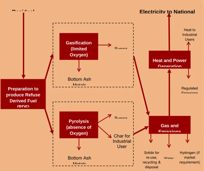
Figure 1 provides examples of generic process flows for ATT technologies.
Residual Electricity to National
Figure 1: ATT Generic Process Flows
There are a wide variety of configurations of ATT plant, and whilst Figure 1 separately shows Pyrolysis and Gasification systems, some processes use both Pyrolysis and Gasification (and potentially also combustion) in sequential stages. As
Preparation to produce Refuse Derived Fuel (RDF) Gasification (limited Oxygen) Pyrolysis (absence of Oxygen) Synga Char for Industrial User Synga Bottom Ash Metals Bottom Ash Metals Gas and Emissions Heat and Power
Generation Heat to Industrial Users Regulated Emissions Solids for re-use, recycling& disposal Hydrogen (if market requirement Water )
noted previously there may also be plasma or other high temperature phases in the initial thermal stage or as ‘polishing’ of the syngas generated by the first process stage.
Waste Reception, Handling and Pre-treatment
The pyrolysis and gasification process is focused on treating the biodegradable based materials present in MSW (e.g. paper, card, putrescible waste, green waste, wood), as well as plastics. Therefore, it is common to remove non-combustible materials and recyclables, (typically metals, glass and non-combustibles) prior to the primary treatment reactor stage (2.2). In addition, depending on the technology employed, the feed material might require processing to remove excess moisture and shredding to reduce the size.
It is the preference (for most ATT processes) to treat only pre-processed residual MSW that is one of the aspects that makes these systems appropriate to be
integrated into a wider municipal waste management strategy. ATT processes may be used in conjunction with other waste treatment technologies such as Mechanical Biological Treatment (MBT) and Mechanical Heat Treatment (MHT). Many
MBT/MHT plant are designed to produce a fuel stream (primarily composed of paper, card and plastics) as one of the outputs from the process. This is commonly referred to as Refuse Derived Fuel (RDF) or Solid Recovered Fuel (see Box 1). This may be more amenable to processing in an ATT plant rather than raw MSW. For more information on MBT and MHT see the separate technology briefs in this series. Box 1: Fuel from Mixed Waste Processing Operations
Various terms are in use to describe solid fuel arising from MBT/MHT processes in the UK, the most common being solid recovered fuel and refuse derived fuel. A CEN Technical Committee (TC 343) has developed standards on fuels prepared from wastes, where the suite of standards uses the terminology Solid Recovered Fuel (SRF) and classify the SRF by a number of characteristics, including by thermal value, chlorine content and mercury content. The use of Refuse Derived Fuel (RDF) as a term has no strict definition and could be generated from a wide variety of waste treatment processes.
A recent development in the UK is the separation between the procurement of waste treatment processes that give rise to a fuel output and the procurement of the market for the utilisation of the fuel generated. In these circumstances a specification of RDF/SRF would be required.
Within this Brief, Refuse Derived Fuel will be used as a term to cover the various fuel products processed from MSW.
Thermal Treatment Reactor
The thermal treatment process, whether pyrolysis or gasification, will produce syngas and solid residue. The composition of the syngas and solid residue will depend on the process conditions employed, which include operating temperature, oxygen level, heating rate and residence time in the reactor. Key types of thermal treatment units available, their application and operating conditions are summarised in Table 1. There are also other factors influencing the process such as direction of gas flow (e.g. horizontally or vertically).
Reactor Typical Application
Operating Conditions
Rotating Kiln Pyrolysis
Typically operate at temperatures of between 300 C and 850 C. Units can accommodate large size feed material (200 mm). Kiln is heated externally and waste is fed in from one end of the kiln which slowly rotates creating a tumbling action. This mixes the waste and ensures contact with the heating surface and gases inside the kiln.
Heated Tube Pyrolysis
The tubes are heated externally and temperatures as high as 800 C are used. The process can accommodate large size feed material. The waste passes through the tube at a set speed to ensure the pyrolysis process is complete.
Surface
Contact Pyrolysis
Small size feed material required and therefore significant pre-treatment is necessary. Process operates at high temperatures and the small size of the feed gives high heating rates. The application of this technology is to maximise the rate of pyrolysis.
Fluidised Bed Gasification
Fluidised bed technology may be used for gasification or combustion processes. The bed is a mass of particles
(typically Alumina) that has similar characteristics to a moving fluid. This is achieved by blowing hot gases through the bed of particles. This system provides good mixing and heat transfer to the incoming waste. Waste is pre-treated to remove large sized material. This technology is well suited to the gasification of refuse derived fuels.
Fixed Bed Gasification
There are a range of different reactor types that come under this heading. A typical example is a grate system where the feed passes along the grate and hot gases pass through the bed of waste heating it.
Table 1: Treatment Reactors
Gas and Residue Treatment Stages
Solids will inevitably be discharged from the process. These solids include metals together with carbon. In the case of gasification, the level of carbon is small; in pyrolysis it is significant. Larger particles of solids in the thermal treatment reactor are usually discharged as bottom ash and slag. In higher temperature processes including those where plasma is applied to the solid residue, the output from the plant may be a vitrous (glassy) slag with minimal leaching properties. This material may have recycling potential as an ‘inert’ aggregate. Lighter ash is usually collected when the gas is separated with the use of cyclones and ultimately filters. In addition, volatile metals such as lead, tin, cadmium and mercury will be carried in the gas until such point that the gas is cooled for them to be sufficiently condensed.
Pollution control strategies for ATT plants will typically be on a smaller scale than for incineration technologies, hence less costly, due to the reduction in the volume of process air required, however compliance with the Industrial Emissions Directive would still be mandatory.
Energy Recovery/Utilisation of Syngas
One of the potential benefits of pyrolysis and gasification is that the syngas can be used in a number of different ways.
In terms of producing energy, the most common configuration is to burn the syngas in a boiler to generate steam. The steam can then be used to generate electricity by passing it through a steam turbine and, if there is a demand local to the plant, for heating. In such instances there is unlikely to be any efficiency benefit over conventional combustion (indeed the Defra Demonstration plant utilising this
approach in the Isle of Wight8 delivered a significantly lower efficiency than would be anticipated through an equivalent incineration plant). Where boilers are utilised, using the heat in addition to generating electricity improves the overall energy efficiency of the system significantly, and should be encouraged. Government incentives (see section 9.4) apply for both electricity and heat recovery from ‘Advanced Conversion Technologies’, which include qualifying Pyrolysis and Gasification systems.
The syngas can also be used to fuel a dedicated gas engine. Syngas from a very well-run gasifier, or further processed for example by reforming, may be suitable for use in a gas turbine. There are very few examples of MSW ATT plant commercially
8
An Energos Gasifier linked to an older (pre‐existing) boiler and flue gas treatment system. The issues with
retrofitting new equipment with old energy recovery infrastructure may have impacted upon the overall
operating on this basis at present. Running these types of plant on syngas is still in its infancy and would require cleaning and cooling prior to use. However, using a gas engine or gas turbine could increase efficiencies for electricity generation. This is of particular relevance if a Combined Cycle Gas Turbine (CCGT) or Combined Heat and Power (CHP) configuration is used (see table 2). Whilst high efficiencies can be achieved using gas engines, the highest efficiencies can only be reached using a high calorific value gas. Efficiencies should be checked if using a lower calorific value gas.
To minimise costs for energy generation the ATT plant could be located adjacent to an existing power plant and the syngas transferred to it. This would also provide benefits if the existing plant has a higher efficiency than a standalone unit. Issues associated with tarring (see section 2.2) should be considered and addressed as appropriate. The power plant may require upgrading, in order to comply with the Industrial Emissions Directive, to improve the abatement system for controlling emissions from the combustion of the syngas, which could incur additional costs. In addition to using the syngas to produce energy, it could also be used as a chemical feedstock. This offers a further option for utilising the syngas but would require the treatment plant to be local to the end user, in order to be a practical solution. This would require very high gas cleanliness; pollutants, notably sulphur and halogens, may need to be removed prior to combustion of the gas. An issue with both the liquid product from Pyrolysis and the Synthesis gas from Gasification or Pyrolysis is the variability of the composition of the product, this is often a limiting factor in terms of ‘high end’ markets.
Where gas is combusted for energy recovery the reduced gas volumes involved in cleaning the combusted gas gives a financial advantage to the process over
equivalent incineration processes. Alkalis such as lime and sodium hydroxide are the favoured reagents for removal of the halogen streams. Sulphur can be removed by a variety of routes, largely dependent on the initial concentration.
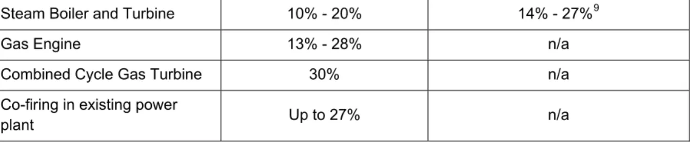
For reference a summary of the potential net electrical generating efficiencies for new build thermal treatment plant employing various energy recovery options is presented in Table 2. For comparison the performance of a new incinerator is also provided. Significantly greater efficiencies are possible by recovering useable heat as well as power. Energy System Efficiencies of Pyrolysis / Gasification Treatment Plant Efficiencies of Incinerator
Steam Boiler and Turbine 10% - 20% 14% - 27%9
Gas Engine 13% - 28% n/a
Combined Cycle Gas Turbine 30% n/a
Co-firing in existing power
plant Up to 27% n/a
Table 2: Potential Net Electrical Generation Efficiencies
Syngas from waste has also been identified as a potential source of hydrogen, which could have applications in both power generation and as a vehicle fuel. There are predicted high energy recovery efficiency benefits of this approach and also carbon dioxide reduction benefits of the hydrogen from waste route compared with the current use of natural gas and electrolysis to produce the gas. There would however be significant purification and reforming required before the gas would be of an appropriate quality for power generation (in turbines or static fuel cells) or transport (in fuel cells). This is an area that is being explored through a range of pilot and emerging technologies in the UK. A limitation and a potential impact on efficiency is the availability of supporting infrastructure for H2 use, however this is an area that could be developed in future as part of a wider package of hydrogen initiatives.
2.5 Summary
Advanced Thermal Treatment processes for MSW are primarily gasification (or pyrolysis with gasification) based. The ATT technologies usually pre-treat MSW prior to the thermal stage and there are a variety of possible energy recovery
configurations available, some of which offer the potential for higher efficiencies than conventional incineration plant. The commercial MSW ATT plant in operation tend to use similar energy recovery systems to incinerators (steam turbines) and therefore do not realise this benefit. Rigorous evaluation of the technology is essential to reduce any operational risks when processing the anticipated feedstock. Over the operational timeline of an ATT plant the composition of waste is likely to alter and the process selected should be robust or flexible enough to treat varying calorific values and compositions of waste feedstock.
9
Typical incinerator efficiencies range from 14% to 24%. A report (Carbon Balances and Energy Impacts of the
Management of UK Wastes, ERM and Golder Associates report for Defra, March 2006),
http://randd.defra.gov.uk/Document.aspx?Document=WR0602_4750_FRP.pdf) states an efficiency range for
3. Markets and Outlets for ATT Outputs
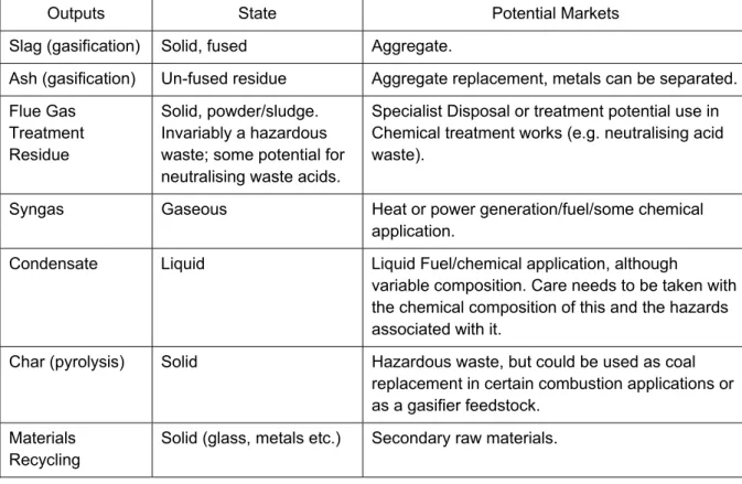
ATT processes will all produce a gas (usually for energy recovery) and a solid residue (slag, ash or char). Some facilities are also designed with mechanical preparation and sorting equipment to extract recyclables. Table 3 summarises the key outputs from ATT processes and the following sections address materials and energy recovery.
Outputs State Potential Markets
Slag (gasification) Solid, fused Aggregate.
Ash (gasification) Un-fused residue Aggregate replacement, metals can be separated.
Flue Gas Treatment Residue
Solid, powder/sludge. Invariably a hazardous waste; some potential for neutralising waste acids.
Specialist Disposal or treatment potential use in Chemical treatment works (e.g. neutralising acid waste).
Syngas Gaseous Heat or power generation/fuel/some chemical
application.
Condensate Liquid Liquid Fuel/chemical application, although
variable composition. Care needs to be taken with the chemical composition of this and the hazards associated with it.
Char (pyrolysis) Solid Hazardous waste, but could be used as coal
replacement in certain combustion applications or as a gasifier feedstock.
Materials Recycling
Solid (glass, metals etc.) Secondary raw materials.
Table 3: Examples of Outputs from ATT Processes
The following section summarises some key issues with regard to these outputs.
3.1 Recovery from ATT
Materials Recycling
Recyclables (metals, glass) derived from either the front end preparation stage of an ATT plant or metals extracted from the back end of the process (i.e. out of the ash) are typically of a lower quality than those derived from a separate household
recyclate collection system, and generally have a lower value accordingly. The types of materials recovered from ATT processes almost always include metals (ferrous and non-ferrous), usually from the front end of the process. Metal removal can help enhance overall recycling levels and enable recovery of certain constituent parts that
would not normally be collected in household systems (e.g. steel coat hangers, scrap metal etc.).
Pyrolysis plants may generate an oil for use in chemical applications, this would be subject to meeting quality requirements of any market outlet. Pyrolysis processes also generate a solid char residue that contains significant amounts of carbon. This will need to be disposed of to landfill, or treated further to reduce the carbon content for example by gasification or combustion. If treated further the final bottom residue could then be recycled as a secondary aggregate. Gasification tends to produce a bottom residue which has a lower carbon content and in higher temperature
processes, has usually been melted or fused, and this could therefore be recycled as aggregate. The recycling of bottom ash would need to be undertaken in accordance with relevant legislation standards10 and it should be noted that incinerator bottom ash, is currently recycled in a number of aggregate applications (see below and also the ‘Incineration’ Waste Management Brief).
Box 2: Use of Incinerator Bottom Ash Aggregate as a constituent in Cement Bound Material (CBM)
10,000 tonnes of Incinerator Bottom Ash Aggregate (IBAA) supplied from Ballast Phoenix’s Edmonton operation was used as a component of cement bound material (CBM). The CBM was laid on the 2012 Olympics Logistics Centre in Chigwell, Essex covering approximately 3Ha of the site with a 150mm of the mixture which contained fine grade (<10mm) IBAA. The low density of the IBAA meant that 100 less truckloads of aggregate were delivered to site when compared to conventional natural aggregate. This contributes to the low carbon footprint attached to the use of IBAA.
10 The Environment Agency is currently developing a Quality Protocol for establishing end of waste criteria for
Use of Incinerator Bottom Ash Aggregate. Image courtesy of Ballast Phoenix
Energy Recovery
ATT processes are designed to recover energy from the waste processed either in the form of fuel production (liquid or gas) or combusting the syngas to generate electricity and/or heat for use on site and export off site. There is also potential for the syngas to be utilised in vehicles, after reforming to produce hydrogen. It is envisaged that the initial market for the hydrogen would be public transport fleets using fuel cell vehicles, and this option is discussed is section 2.4.
Electricity generated from the biomass fraction of waste in gasification and pyrolysis plants should be eligible for support under the Renewables Obligation11 and
Renewable Heat Incentive12 scheme, as noted in section 9.4.
11
DECC RO website:
www.decc.gov.uk/en/content/cms/meeting_energy/renewable_ener/renew_obs/renew_obs.aspx.
12 DECC RHI website:
It should be noted that the processes using Refuse Derived Fuel will have already incurred energy usage in the preparation of the fuel and this prepared material will have a higher calorific value than raw MSW.
4. Track
Record
Whilst ATT technologies are established technologies for the treatment of certain specific waste streams, it is only in recent years, in the UK, that pyrolysis and gasification have been commercially applied to the treatment of MSW.
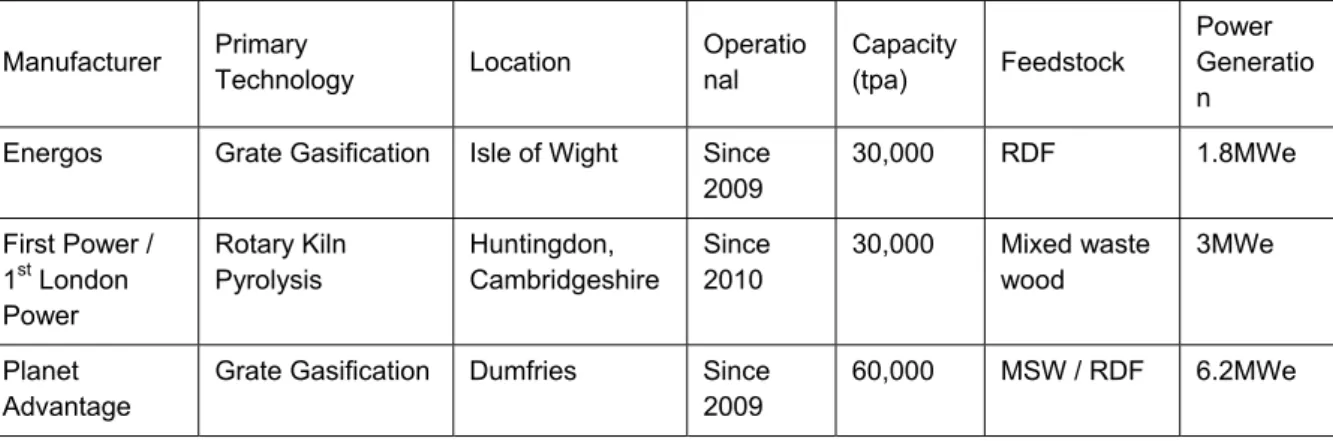
The prime drivers in the UK for the development of these technologies are increasing landfill costs (as a result of the Landfill Tax) and the implementation of the Landfill Directive. The development of pyrolysis and gasification technologies for MSW are in relatively early stages of commercial operation in the UK, but more established plant have been built and are in operation in North America, Europe and Japan. Table 4 provides examples of ATT facilities in the UK, treating MSW and other types of waste. Manufacturer Primary Technology Location Operatio nal Capacity (tpa) Feedstock Power Generatio n Energos Grate Gasification Isle of Wight Since
2009 30,000 RDF 1.8MWe First Power / 1st London Power Rotary Kiln Pyrolysis Huntingdon, Cambridgeshire Since 2010 30,000 Mixed waste wood 3MWe Planet Advantage
Grate Gasification Dumfries Since 2009
60,000 MSW / RDF 6.2MWe
Table 4: Example ATT Facilities in the UK
The following case studies detail ATT plants under planning/development and operational that can be described as technology demonstration sites/facilities.
Energos Gasification Facility, Isle of Wight
This project was partly funded through the Defra New Technologies Demonstrator Programme and is operated by Biffa. It comprises:
• Gasification facility integrated with existing MRF and in-vessel composting facilities to process residual MSW, in the form of RDF.
• Capacity of 30,000tpa RDF.
• Consumes RDF with a high biodegradable content (70 - 80%) and a calorific value of 11 – 14 MJ/kg.
• Export of approximately 1.8 MWe of renewable electricity and locally usable waste heat.
SITA / Cynar Pyrolysis Plant, Avonmouth
A pyrolysis based technology developed by Cynar, and in partnership with SITA, is under development in Bristol, with the aim of establishing a series of similar plant around the UK. The plant operates on end of life plastics from the commercial / industrial (or other) sources and converts the waste into Diesel, Kerosene and Gasoline grade products. The syngas from the Pyrolysis process and some of the liquid fuel products are utilised to run the process, the remainder will be marketed at potential fuel / chemicals customers.
Avonmouth MBT / ATT Facility, New Earth Solutions
New Earth’s fifth and largest facility was formally opened in September 2011
following a 5 month commissioning period. At 200,000 tpa capacity the MBT facility uses waste preparation and sorting technology to treat primarily residual household waste from the West of England Partnership, comprising the local authorities of Bath and North East Somerset, Bristol City, North Somerset and South Gloucestershire, but also commercial and industrial waste of a similar composition.
The facility, which was developed on a disused industrial site, aims to divert ~95% of waste away from landfill - helping local authorities to meet landfill diversion targets and maximizing the recycling potential of the waste it treats by extracting valuable metals and plastics and creating a compost-like output from the organic waste. From the fraction of the waste which cannot be recycled, New Earth produce a refuse-derived fuel product. Currently this is being shipped to Europe under the trans-frontier shipment regulations. However, on land adjacent to the MBT facility, New Earth are currently installing an energy recovery plant utilising the patented New Earth Advanced Thermal (NEAT) energy recovery technology. When fully operational in 2013 the plant will generate 13MW of electricity, enough to meet the needs of nearly 25,000 homes in the Bristol area.
5. Contractual and Financing Issues
5.1 Grants and Funding
Development of ATT plant will usually involve a minimum capital expenditure of several million pounds. There are a number of potential funding sources for Local Authorities planning to develop such facilities, including:
Capital Grants: general grants may be available from national economic initiatives and EU structural funds;
Prudential Borrowing: the Local Government Act 2003 provides for a
'prudential' system of capital finance controls, which is covered in detail by the Chartered Institute of Public Finance and Accountancy (CIPFA) 2009
Prudential Code for Capital Finance;
Waste Infrastructure (WI) credits and Private Sector Financing: waste authorities were able to obtain grant funding from central Government to support the expenditure required to deliver new facilities.. However, there is no intention to issue new WI credits at the date of this publication;
Other Private-Sector Financing: a contractor may be willing to enter a contract to provide a new facility and operate it. The contractor’s charges for this may be expressed as gate fees;
Existing sources of local authority funding: for example from National Non-Domestic Rate payments (distributed by central government)13, credit borrowing where government credit approvals are received, local tax rising powers (council tax), and income from rents, fees, charges and asset sales (capital receipts). In practice capacity for this will be limited.
The Government is encouraging the use of different funding streams, otherwise known as a ‘mixed economy’ for the financing and procurement of new waste
infrastructure to reflect the varying needs of local authorities. The Government Green Investment Bank is investing in waste infrastructure. This option may provide
financing for appropriate projects moving forward.
13
Except, for example, in ‘Core Cities’ where authorities may be eligible for infrastructure support through the
application of business rates under the ‘New Development Deals’ and ‘Economic Investment Funds’
mechanisms of the Governments City Deals programme. See ‘Unlocking Growth in Cities: City Deals – Wave 1’,
5.2 Contractual Arrangements
Medium and large scale municipal waste management contracts, since January 2007, are likely to be procured through the EU Competitive Dialogue (CD)
programme under the Public Contact Regulations14. This is dialogue between an authority and the bidders with the aim of developing a suitable technical or legal position against which all the bidders can submit a formal bid. More information on CD is available from the Local Partnership website at
http://www.localpartnerships.org.uk/PageContent.aspx?id=9&tp=Y.
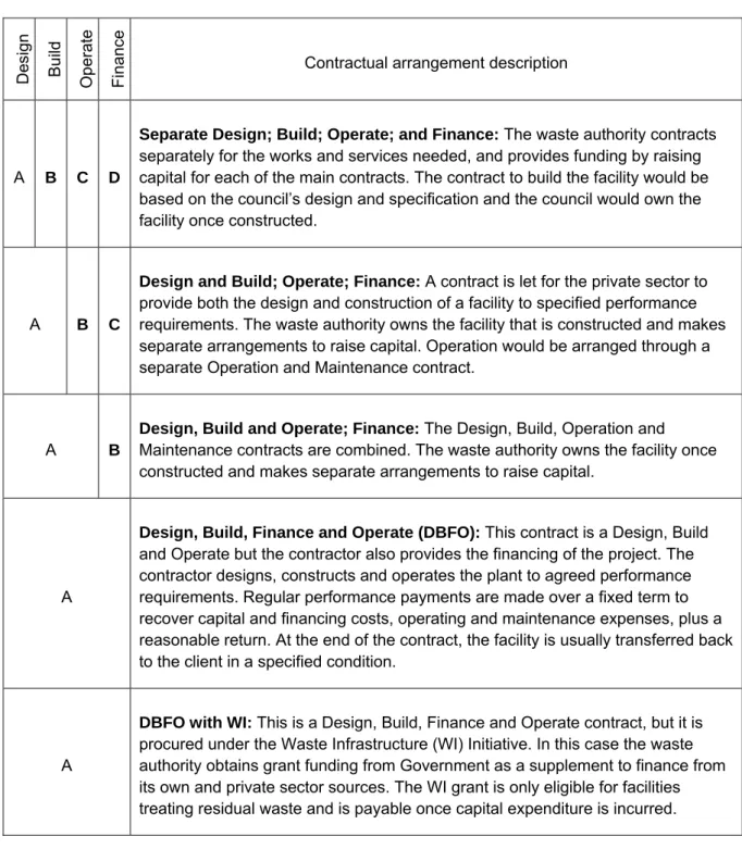
The available contractual arrangement between the Private Sector Provider (PSP) and the waste disposal authority (or partnership) may be one of the following:
De
sign
Build
Operate Finan
ce
Contractual arrangement description
A B C D
Separate Design; Build; Operate; and Finance: The waste authority contracts separately for the works and services needed, and provides funding by raising capital for each of the main contracts. The contract to build the facility would be based on the council’s design and specification and the council would own the facility once constructed.
A B C
Design and Build; Operate; Finance: A contract is let for the private sector to
provide both the design and construction of a facility to specified performance requirements. The waste authority owns the facility that is constructed and makes separate arrangements to raise capital. Operation would be arranged through a separate Operation and Maintenance contract.
A B
Design, Build and Operate; Finance: The Design, Build, Operation and Maintenance contracts are combined. The waste authority owns the facility once constructed and makes separate arrangements to raise capital.
A
Design, Build, Finance and Operate (DBFO): This contract is a Design, Build
and Operate but the contractor also provides the financing of the project. The contractor designs, constructs and operates the plant to agreed performance requirements. Regular performance payments are made over a fixed term to recover capital and financing costs, operating and maintenance expenses, plus a reasonable return. At the end of the contract, the facility is usually transferred back to the client in a specified condition.
A
DBFO with WI: This is a Design, Build, Finance and Operate contract, but it is procured under the Waste Infrastructure (WI) Initiative. In this case the waste authority obtains grant funding from Government as a supplement to finance from its own and private sector sources. The WI grant is only eligible for facilities treating residual waste and is payable once capital expenditure is incurred.
Table 5: Available Contractual Arrangement Configurations
The majority of large scale waste management contracts currently being procured in England are DBFO contracts and many waste disposal authorities in two tier English arrangements (County Councils) are currently seeking to partner with their Waste Collection Authorities (usually District or Borough Councils). Sometimes partnerships are also formed with neighbouring Unitary Authorities to maximise the efficiency of the waste management service and make the contract more attractive to the Private Sector Provider, for example the Greater Manchester Waste Disposal Authority combining nine of ten unitary authorities in the city region.
Contracts are becoming more ‘output’ led since contractors increasingly have to build proposals around obligated targets placed on authorities such as for recycling yields.
A fundamentally important issue in consideration of the bankability of any waste treatment project is the acceptable risk profile of the procurement in question (i.e. risk allocation within the contract), and project risk in terms of ability to deliver the infrastructure required (planning, technology, availability, reliability and available secure markets for process outputs). There are a number of steps that may be taken by contracting authorities and waste management solution providers in order to minimise the risk profile and help in the delivery of the project as a whole. The following examples of further reading explore these issues:
• ‘Rubbish to Resource: Financing New Waste Infrastructure’, Associate Parliamentary Sustainable Resource Group (APSRG), September 2011, available at http://www.policyconnect.org.uk/apsrg/rubbish-resource-financing-new-waste-infrastructure.
• Local Authority funding examples
http://www.defra.gov.uk/environment/waste/local-authorities/widp/pfi-projects/.
• Guidance documents on waste management procurement
http://www.defra.gov.uk/environment/waste/local-authorities/widp/widp-guidance/.
• For Works Contracts: the NEC3 contracts (available at www.neccontract.com – formerly the Institute of Civil Engineers ‘New Engineering Contract’).
• Local Partnerships provide guidance to local authorities concerning partnership opportunities and achieving optimum service delivery and efficiencies,
6. Planning and Permitting Issues
This section contains information on the planning and regulatory issues associated with ATT facilities based on legislative requirements, formal guidance, good practice documents and examples of permits and planning applications.
6.1 Planning Application Requirements
All development activities are covered by Planning laws and regulations. Minor development may be allowed under Permitted Development rights but in almost all cases new development proposals for waste facilities will require planning
permission.
Under certain circumstances new waste facilities can be developed on sites
previously used for General Industrial (B2) or Storage and Distribution (B8) activities. In practice even where existing buildings are to be used to accommodate new waste processes, variations to existing permissions are likely to be required to reflect
changes in traffic movements, emissions etc.
Under changes to the planning system introduced in 2006 all waste development is now classed as ‘Major Development’. This has implications with respect to the level of information that the planning authority will expect to accompany the application and also with respect to the likely planning determination period. The target determination periods for different applications are:
• Standard Application – 8 weeks
• Major Development – 13 weeks
• EIA Development – 16 weeks
The principal national planning policy objectives associated with waste management activities are set out in Planning Policy Statement (PPS) 10 ‘Planning for Sustainable Waste Management’ published in March 2011. Supplementary guidance is also contained within the Companion Guide to PPS 1015. Both of these documents can be accessed via the Department of Communities and Local Government (DCLG website.
)
It should be noted that with the publication of the National Planning Policy Framework (NPPF) in March 2011, virtually all pre-existing Planning Policy Statements (PPS) and Planning Policy Guidance (PPG) notes have now been replaced. However, as the Framework does not contain specific waste policies since
these will be published alongside the national waste management plan for England, PPS10 will remain in place until the new Plan is adopted.
PPS 10 places the emphasis on the plan led system, which should facilitate the development of new waste facilities through the identification of sites and policies in the relevant local development plan. Separate guidance on the content and
validation of planning applications is also available from DCLG through their website16. Individual Planning Authorities can set out their own requirements with respect to supporting information and design criteria through Supplementary
Planning Documents linked to the Local Development Framework (which is likely to be referred to as the ‘Local Plan’ in the future under the NPPF system). It is
important that prospective developers liaise closely with their Local Planning Authorities over the content and scope of planning applications.
Key Issues
When considering the planning implications of an ATT plant the key issues that will need to be considered are common to most waste management facilities, and are:
• Plant/Facility Siting;
• Traffic;
• Air Emissions / Health Effects;
• Dust / Odour;
• Flies, Vermin and Birds;
• Noise;
• Litter;
• Water Resources;
• Visual Intrusion;
• Size and Landtake; and
• Public Concern.
A brief overview of the planning context for each of these issues is provided in the following pages.
Plant Siting
PPS 10 and its Companion Guide contain general guidance on the selection of sites suitable for waste facilities. This guidance does not differentiate between facility types and states:
“Most waste management activities are now suitable for industrial locations, many fall within the general industrial class in the Use Classes
Order (as amended).17
The move towards facilities and processes being enclosed within purpose designed buildings, rather than in the open air, has accentuated this trend. The guidance goes on to state:
“With advancement in mitigation techniques, some waste facilities may also be considered as light industrial in nature and therefore compatible with residential development. In more rural areas, redundant agricultural and forestry buildings may also provide suitable opportunities, particularly for the management of agricultural wastes”.
The following general criteria would also apply to the siting of new ATT plants:
• ATT processes can be similar in appearance and characteristics to various process industries. It would often be suitable to locate facilities on land previously used for general industrial activities or land allocated in development plans for such (B2) uses;
• Facilities are likely to require good transport infrastructure. Such sites should either be located close to the primary road network or alternatively have the potential to be accessed by rail or barge;
• The location of such plants together with facilities producing RDF (such as MBT and MHT facilities) could be advantageous. The potential for co-location of such facilities on resource recovery parks or similar is also highlighted in the Companion Guide; and
• The potential for export of energy to host users or the national grid should also be a key consideration in the siting of ATT facilities. The Renewables Obligation provides a price premium for electricity generated from renewable sources (the biomass fraction of waste) in gasification and pyrolysis plants consideration should always be given to utilising not only the electricity from the plant but also the waste heat in order to maximise energy and carbon benefits.
Traffic
ATT facilities may be served by large numbers of Large (Heavy) goods vehicles (LGVs) (depending on the scale of the facility) with a potential impact on local roads and the amenity of local residents. It is likely that the site layout/road configuration will need to be suitable to accept a range of light and heavy vehicles. For a
17 For more information on change of use classes see,
50,000tpa capacity plant, of the order of 20 Refuse Collection Vehicles per day would be anticipated.
Air Emissions / Health Effects
In terms of complying with the Industrial Emissions Directive (IED) the major emission from a plant with energy recovery is the release of flue gases from the combustion of the syngas (and in some instances also the residual solid, if it has high carbon content). The clean-up required for the flue gases is dependent on the process from which they have been generated. Entrained (fine) particles in the syngas can either be removed before or after combustion depending on the treatment process and combustion technology employed.
One of the main benefits claimed by manufacturers for pyrolysis and gasification plant is that emissions of pollutants are lower than those from conventional
incineration, and also that plant are designed to comply with the emission limits set out in the directive. The flue gases are maintained at high temperatures for a specified minimum time, before being rapidly cooled. These stages minimise the formation of potentially harmful substances. Following the thermal stage, the flue gases are normally treated to remove oxides of nitrogen, mercury, dioxins and furans, and acid gases, although specific treatment may not be needed if the in-process controls give the required performance. The air stream is then passed through a bag filter to remove particulate matter. The residual emissions to air from waste thermal treatment processes are discharged from a stack which is designed to provide sufficient dispersion of the low levels of remaining air pollutants.
Waste thermal treatment facilities need to rely on post-treatment gas clean-up measures such as those described above to achieve the requirements of the Directive. The use of an air filtration system to remove particulate matter from the flue gases results in a fine, dusty waste stream referred to as “air pollution control residues” (or in some cases Flue Gas Treatment residues). This waste stream must be disposed of appropriately.
Emissions of many parameters need to be monitored continuously. This enables process operators to comply with the emissions limits set out in operating permits, which as a minimum reflect those in the Industrial Emissions Directive (IED).
Some substances, including dioxins, furans and some metals, cannot be measured continuously or it may be prohibitively expensive to do so. Some substances such as dioxins and furans can be continuously sampled, with analysis carried out
periodically to give the average amount emitted over a longer period. Emissions of substances which cannot be measured continuously are normally measured periodically under the terms of the operating permit. Routine day-to-day control is achieved by ensuring that surrogate indicators such as combustion temperature,
particulate emissions and hydrogen chloride emissions are within the permitted limits.
The Health Protection Agency (HPA) consider the potential health impacts of thermal treatment plant, notably Incinerators, and provides input into each Environmental Permit application. They have provided a position statement18 on the subject which states:
“While it is not possible to rule out adverse health effects from modern, well regulated municipal waste Incinerators with complete certainty, any potential damage to the health of those living close-by is likely to be very
small, if detectable. This view is based on detailed assessments of the effects of air pollutants on health and on the fact that modern and well managed municipal waste Incinerators make only a very small contribution
to local concentrations of air pollutants.”
Dust / Odour
Any waste management operations can give rise to dust and odours. These can be minimised by good building design, performing all operations under controlled conditions indoors, good working practices and effective management undertaken for dust suppression from vehicle movements. The control of odour from waste reception areas of ATT facilities needs careful consideration. Because ATT facilities are located within an enclosed building, potential odour emissions can normally be controlled through the building ventilation system. Many ATT processes are
designed to operate under negative pressure within buildings in order to minimise dust and odour problems.
Flies, Vermin and Birds
The enclosed nature of ATT operations will limit the potential to attract vermin and birds. However, during hot weather it is possible that flies could accumulate, especially if they have been brought in during delivery of the waste.
Effective housekeeping and on site management of tipping and storage areas is essential to minimise the risk from vermin and other pests. In some operations waste heat from the process may be passed through fresh inputs waste so temperatures
exceed levels at which flies can survive. Similarly, waste storage time in some ATT plant is designed to be less than the breeding cycle of vermin such as rats. The use of RDF as a feedstock would reduce this issue relative to raw waste.
Noise
Noise is an issue that will be controlled under permitting regulations and noise levels at nearby sensitive receptors can be limited by a condition of a planning permission. The main contributors to noise associated with ATT are likely to be:
• Vehicle movements / manoeuvring;
• Traffic noise on the local road networks;
• Mechanical processing such as waste preparation;
• Air extraction fans and ventilation systems;
• Steam turbine units; and
• Air cooled / other condenser units.
Litter
Any waste which contains plastics and paper is more likely to lead to litter problems. With ATT, litter problems can be minimised if good working practices are adhered to, vehicles use covers and reception and processing are undertaken indoors.
Water Resources
Common to many new waste treatment processes the enclosed nature of the operations significantly reduces the potential for impacts on the water environment. The greatest potential for pollution to surface/ground water is linked to the
arrangement for delivery of waste and the collection of processed materials. Pollution of water is unlikely due to ATT facilities being under cover and rainfall is unlikely to come into contact with the process. Even so, any wash down waters or liquid within the waste will need to be managed using a drainage system on site. The level of water usage will be specific to the technology and therefore it is not possible to provide detail on the nature of the effluent that might be generated and how it should be managed. However, as part of the permitting requirements for a facility a management plan would be required for effluent.
Design Principles and Visual Intrusion
Current planning guidance in PPS 10 emphasises the importance of good design in new waste facilities, the importance of which is echoed by the National Planning Policy Framework in relation to the design of the built environment as a whole. Good design principles and architect input to the design and physical appearance of large
scale buildings and structures such as ATT plant is essential. Buildings should be of an intrinsically high standard and should not need to be screened in most cases. Good design principles also extend to other aspects of the facility including having regard to issues such as:
• Site access and layout;
• Energy efficiency;
• Water efficiency; and
• The general sustainability profile of the facility.
Construction of any building will have an effect on the visual landscape of an area. Visual intrusion issues should be dealt with on a site specific basis and the following items should be considered:
• Direct effect on landscape by removal of items such as trees or undertaking major earthworks;
• Site setting – is the site close to listed buildings, conservation areas or sensitive viewpoints;
• Existing large buildings and structures in the area;
• The potential of a stack associated with some air clean up systems for mixed waste processing operations may impact on visual intrusion;
• Appropriate use of landscaping features (trees, hedges, banks etc.) not for screening but to enhance the setting of the facility;
• The number of vehicles accessing the site and their frequency; and
• Many of these facilities are housed in ‘warehouse’ type clad steel buildings, however use of good design techniques can help minimise visual intrusion. For more information on the role of good design in waste facilities, please see the Defra publication ‘Designing Waste Facilities: A Guide to Modern Design in Waste’, which can be found at
http://archive.defra.gov.uk/environment/waste/localauth/documents/designing-waste-facilities-guide.pdf.
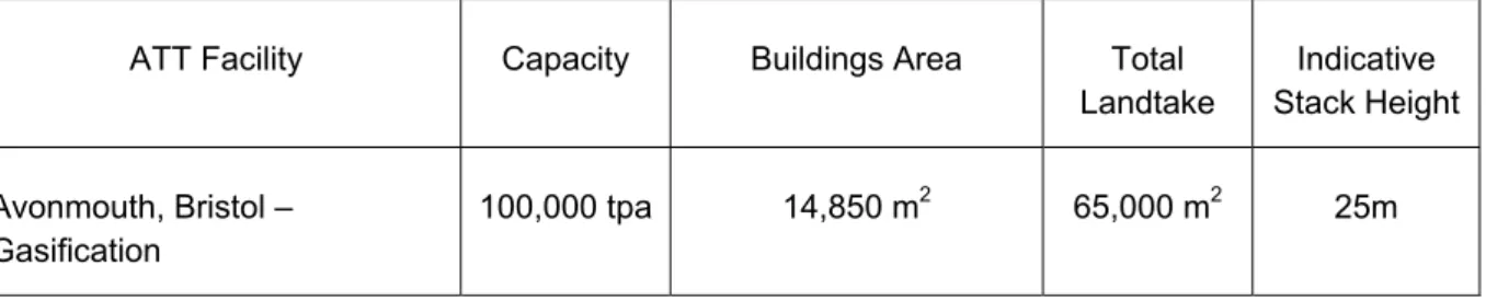
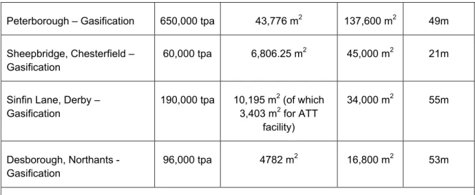
Size and Land Take
Table 6 shows the land area required for the building footprint and also for the entire site (including supporting site infrastructure) for examples of thermal processes.
ATT Facility Capacity Buildings Area Total
Landtake Indicative Stack Height Avonmouth, Bristol – Gasification 100,000 tpa 14,850 m2 65,000 m2 25m
Peterborough – Gasification 650,000 tpa 43,776 m2 137,600 m2 49m
Sheepbridge, Chesterfield – Gasification
60,000 tpa 6,806.25 m2 45,000 m2 21m
Sinfin Lane, Derby – Gasification
190,000 tpa 10,195 m2 (of which
3,403 m2 for ATT facility) 34,000 m2 55m Desborough, Northants - Gasification 96,000 tpa 4782 m2 16,800 m2 53m
Note. All data taken from planning application documents.
Table 6: Examples of Size and Landtake of Proposed Thermal Treatment Facilities
ATT plants are usually of modular design and scalable to suit the requirements of different waste management operators, offering flexible capacity and operational patterns.
Public Concern
Section 7, Social and Perception Issues, relates to public concern. In general public concerns about waste facilities in general relate to amenity issues (odour, dust, noise, traffic, litter etc.). For facilities that form part of a larger development which include thermal treatment of the RDF, including ATT processes, health concerns can also be a perceived issue. Public concern founded upon valid planning reasons (known as ‘material considerations’) can be taken into account when considering a planning application.
Environmental Impact Assessment
It is likely that an Environmental Impact Assessment (EIA) will be required for an ATT facility as part of the planning process. Whether a development requires a statutory EIA is defined under the EIA Regulations 201119. Care should be taken with the difference in meaning between ‘treatment’ and ‘disposal’ when applying these regulations, an ATT facility is a waste treatment facility and is not a waste disposal installation. The existing additional guidance in DETR circular 02/99 withdrawn following the publication of the new EIA Regulations; however no proposals have yet been made as to a replacement.
is to be
6.2 Licensing / Permitting
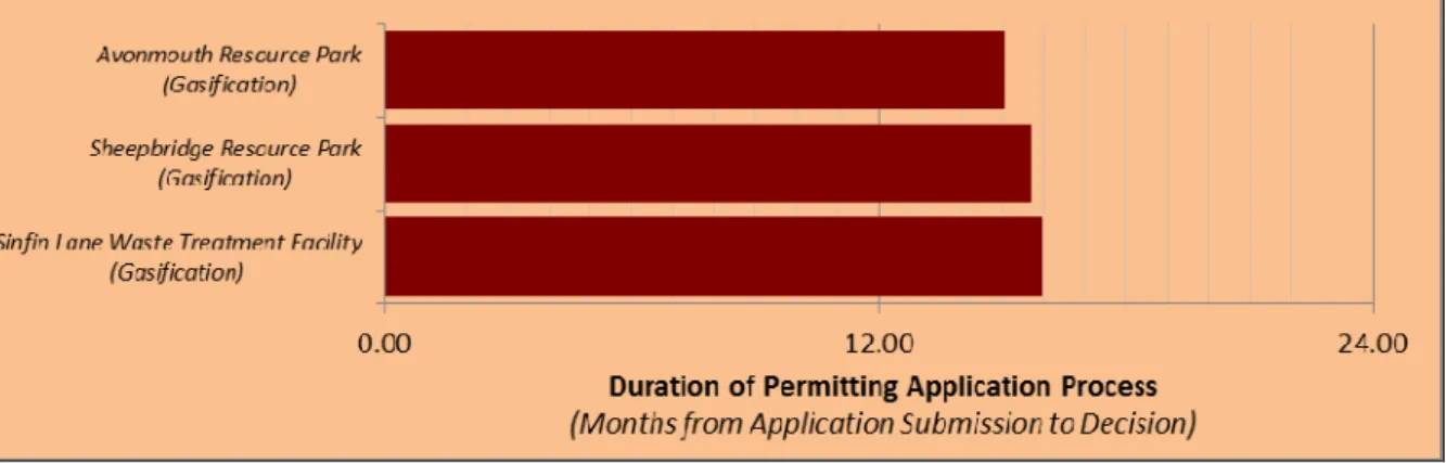
The Environmental Permitting Regulations (EPR) have been amended on several occasions20 and combined the previously separate Pollution Prevention and Control (PPC) and Waste Management Licensing (WML) Regulations. All commercial scale ATT facilities require a permit.
It is the scope of the proposal, in addition to local environmental circumstances, that will determine the nature and complexity of the permit, and hence the process and, to a certain degree, timescale from initiation to permit determination. Figure 2 shows example permit timescales for ATT processes in the UK. Whilst the examples shown are relatively consistent in terms of determination period, the scope and nature of the proposal can have a significant influence on the duration of the process as a whole. Furthermore in some instances multi-operator permits are needed where for example the ATT process may be operated by one contractor and the CHP plant may be operated by another, again such aspects can add time and complexity into the permitting process.
Figure 2 Example Environmental Permit timescales for Gasification facilities
The process of obtaining an environmental permit is an initial step in an on-going management process for delivery of the requirements of the Permit and ensuring compliance and use of Best Available Techniques. This may include reporting, improvement plans and other on-going activities. There is also a facility within the regulations for the variation of Permits. In the case of municipal waste treatment facilities, where there is a significant operational life anticipated (15 – 30 years), the option to vary may be an important one to allow incorporation of new technology or methods within the installation. In addition, the Permit may be transferred or
surrendered (e.g. at the end of a projects operational life). These aspects should be appropriately considered and will involve management processes and reporting / actions as required by the Environment Agency (for example completion reports, decommissioning plans, etc.).
For more information, please see the permitting pages of the Environment Agency’s site at
7. Social and Perception Issues
This section contains a discussion of the social and environmental considerations of ATT facilities.
7.1 Social Considerations
Any new facility is likely to impact on local residents and may result in both positive and negative impacts. Potential impacts on local amenity (odour, noise, dust,
landscape) are important considerations when siting any waste management facility. These issues are examined in more detail in the Planning and Permitting section of this Brief. Transport impacts associated with the delivery of waste and onward transport of process outputs may lead to impacts on the local road network. The Planning and Permitting section of this Brief provides an estimate of potential vehicle movements.
An ATT facility may also provide positive social impacts in the form of employment, educational opportunities and a source of low cost heat. Typical employment for an ATT plant of 50,000tpa capacity would be in the order of 25 – 35 permanent staff. The plant could operate on a shift system, to allow for 24-hour operations. These facilities are also likely to provide vocational training for staff. New facilities may be built with a visitor centre to enable local groups to view the facility and learn more about how it operates.
7.2 Public Perception
Changes to waste management arrangements in local areas as a result of
continually improving recycling and landfill diversion performance, often creates a higher profile for the service through the media. Many people as a result of greater publicity, targeted education and more comprehensive waste services are
participating, to a greater extent, in waste reduction and recycling activities. This leads to a greater level of engagement in waste management activity. There is still however a significant challenge with regard to acceptance of waste management facilities.
Public opinion on waste management issues is wide ranging, and can often be at extreme ends of the scale. Typically, the most positively viewed waste management options for MSW are recycling and composting. However, this is not necessarily reflected in local attitudes towards the infrastructure commonly required to process waste to compost, or sort mixed recyclables. It should be recognised that there is