Open-Systems Host Attachment Guide
Hitachi Virtual Storage Platform G1000
Hitachi Virtual Storage Platform
Hitachi Unified Storage VM
Hitachi Universal Storage Platform V/VM
F
ASTF
INDL
INKSContents
Product Version
Getting Help
© 2014 Hitachi, Ltd. All rights reserved.
No part of this publication may be reproduced or transmitted in any form or by any means, electronic or mechanical, including photocopying and recording, or stored in a database or retrieval system for any purpose without the express written permission of Hitachi, Ltd.
Hitachi, Ltd., reserves the right to make changes to this document at any time without notice and assumes no responsibility for its use. This document contains the most current information available at the time of
publication. When new or revised information becomes available, this entire document will be updated and distributed to all registered users.
Some of the features described in this document might not be currently available. Refer to the most recent product announcement for information about feature and product availability, or contact Hitachi Data Systems Corporation at https://portal.hds.com.
Notice: Hitachi, Ltd., products and services can be ordered only under the terms and conditions of the
applicable Hitachi Data Systems Corporation agreements. The use of Hitachi, Ltd., products is governed by the terms of your agreements with Hitachi Data Systems Corporation.
Notice on Export Controls. The technical data and technology inherent in this Document may be subject to
U.S. export control laws, including the U.S. Export Administration Act and its associated regulations, and may be subject to export or import regulations in other countries. Reader agrees to comply strictly with all such regulations and acknowledges that Reader has the responsibility to obtain licenses to export, re-export, or import the Document and any Compliant Products.
Hitachi is a registered trademark of Hitachi, Ltd., in the United States and other countries. Hitachi Data Systems is a registered trademark and service mark of Hitachi, Ltd., in the United States and other countries. Archivas, Essential NAS Platform, Hi-Track, ShadowImage, Tagmaserve, Tagmasoft, Tagmasolve, Tagmastore, TrueCopy, Universal Star Network, and Universal Storage Platform are registered trademarks of Hitachi Data Systems Corporation.
AIX, AS/400, DB2, Domino, DS6000, DS8000, Enterprise Storage Server, ESCON, FICON, FlashCopy, IBM, Lotus, MVS, OS/390, RS/6000, S/390,System z9, System z10, Tivoli, VM/ESA, z/OS, z9, z10, zSeries, z/VM, and z/VSE are registered trademarks or trademarks of International Business Machines Corporation.
All other trademarks, service marks, and company names in this document or website are properties of their respective owners.
Contents
Preface ... ix
Intended audience ... x
Product version ... x
Release notes ... x
Document revision level ... xi
Changes in this revision ... xi
Referenced documents ... xi
Document conventions ... xii
Convention for storage capacity values ... xiv
Accessing product documentation ... xiv
Getting help ... xv
Comments ... xv
Overview of host attachment ... 1-1
About the Hitachi RAID storage systems ... 1-2
Device types ... 1-3
Host queue depth ... 1-6
Host attachment workflow ... 1-7
Preparing for host attachment ... 2-1
Installation and configuration requirements ... 2-2
Installing the Hitachi RAID storage system ... 2-4
Configuring the Hitachi RAID storage system ... 2-5
Setting the system option modes ... 2-5
Configuring the ports ... 2-6
Setting the host modes and host mode options ... 2-7
Installing and configuring the host ... 2-12
Installing the host OS software ... 2-12
Installing the LVM software ... 2-12
Installing the failover software ... 2-13
Installing the SNMP software ... 2-14
Installing and configuring the host FC adapters ... 2-15
Connecting the Hitachi RAID storage system to the host ... 2-17
Configuring the new hosts and new LU paths ... 2-18
AIX
®configuration and attachment ... 3-1
Hitachi storage system configuration for AIX
®operations ... 3-2
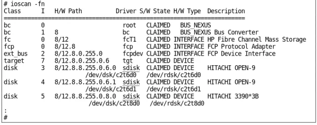
Verifying new device recognition ... 3-3
Configuring the new devices ... 3-5
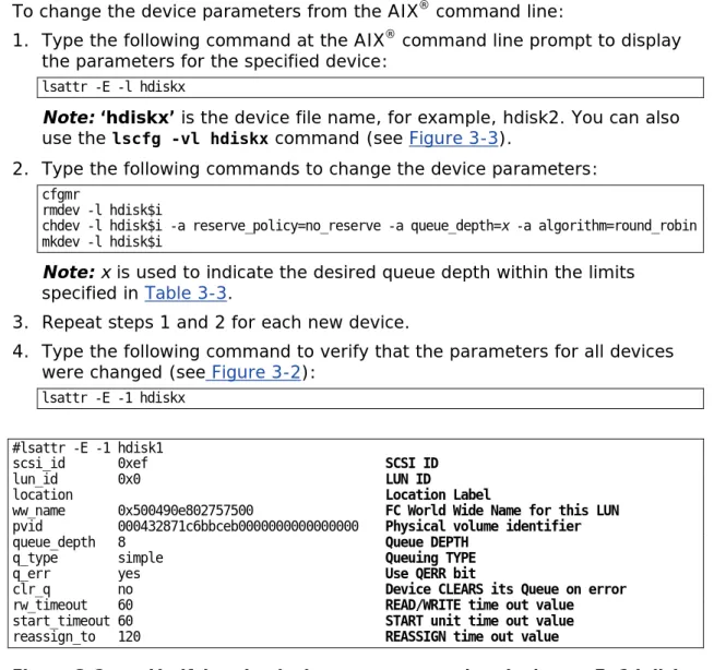
Changing the default device parameters ... 3-5
Changing device parameters from the AIX
®command line ... 3-6
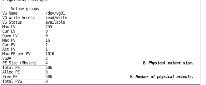
Assigning new devices to volume groups and setting partition sizes ... 3-7
Creating, mounting, and verifying file systems ... 3-10
Creating the file systems ... 3-10
Mounting and verifying file systems ... 3-14
Using the Object Data Manager with Hitachi RAID storage ... 3-15
Overview of ODM ... 3-15
ODM advantages and cautions ... 3-16
Using ODM ... 3-17
Discovering new devices ... 3-17
Deleting devices ... 3-17
Queue depth and read/write timeout values ... 3-17
Online device installation ... 3-18
Online LUSE configuration ... 3-19
Creating and mounting the file systems ... 3-19
Expanding the logical volume (LP400) ... 3-21
Expanding the file system (up to 3 GB) ... 3-22
Increasing the file system (up to 40 GB) ... 3-22
Troubleshooting for AIX
®host attachment ... 3-24
HP-UX configuration and attachment ... 4-1
Hitachi storage system configuration for HP-UX operations... 4-2
Configuring the new devices ... 4-3
Verifying new device recognition ... 4-4
Verifying device files and the driver ... 4-7
Creating device files ... 4-8
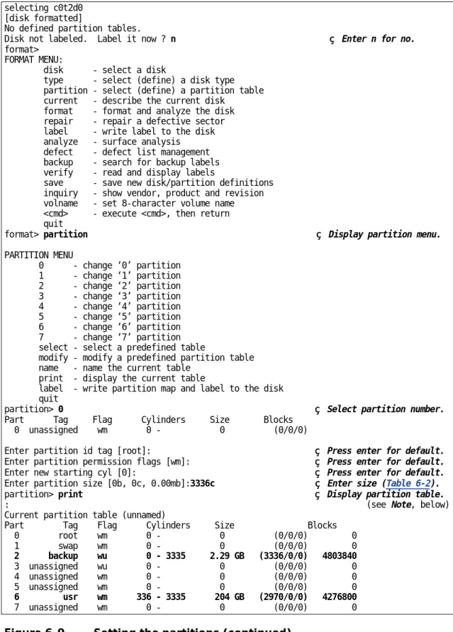
Partitioning disk devices ... 4-10
Creating physical volumes ... 4-11
Creating volume groups ... 4-12
Creating logical volumes ... 4-15
Creating file systems ... 4-17
Setting device parameters ... 4-18
Setting the IO time-out parameter ... 4-18
Setting the queue depth parameter ... 4-19
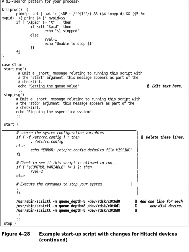
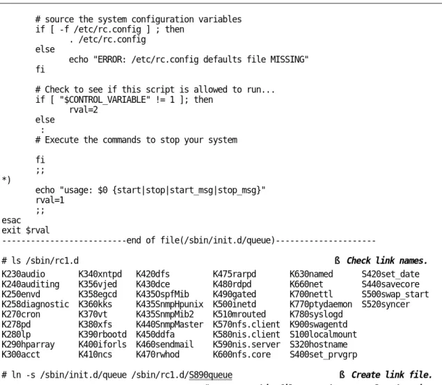
Creating and registering the queue depth start-up script ... 4-21
Creating mount directories ... 4-25
Mounting and verifying file systems ... 4-26
Setting and verifying auto-mount parameters ... 4-27
Online device installation ... 4-28
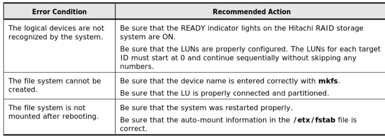
Troubleshooting for HP-UX host attachment ... 4-29
Red Hat Linux configuration and attachment ... 5-1
Hitachi storage system configuration for Red Hat Linux operations ... 5-2
Device Mapper (DM) Multipath configuration ... 5-3
Verifying new device recognition ... 5-4
Configuring the new devices ... 5-6
Setting the number of logical units ... 5-6
Partitioning the devices ... 5-7
Creating, mounting, and verifying the file systems ... 5-8
Creating the file systems ... 5-8
Creating the mount directories ... 5-8
Mounting the new file systems ... 5-8
Verifying the file systems ... 5-8
Setting the auto-mount parameters... 5-9
Troubleshooting for Red Hat Linux host attachment ... 5-10
Solaris configuration and attachment ... 6-1
Hitachi storage system configuration for Solaris operations ... 6-2
FCA configuration for Solaris ... 6-3
Verifying the FCA installation ... 6-3
Setting the disk and device parameters ... 6-4
Configuring the new devices ... 6-6
Setting and recognizing the LUs ... 6-6
Verifying recognition of new devices ... 6-9
Partitioning and labeling the new devices ... 6-11
Creating and mounting the file systems ... 6-28
Creating the file systems ... 6-28
Creating and verifying the mount directories ... 6-29
Mounting and verifying the file systems ... 6-30
Setting and verifying the auto-mount parameters ... 6-32
Troubleshooting for Solaris host attachment ... 6-34
Verbose mode troubleshooting ... 6-34
Online device installation ... 6-36
Sun fibre-channel host bus adapter installation ... 6-36
Using MPxIO path failover software ... 6-37
SUSE Linux configuration and attachment ... 7-1
Hitachi storage system configuration for SUSE Linux operations ... 7-2
Device Mapper (DM) Multipath configuration ... 7-3
Verifying new device recognition ... 7-4
Configuring the new devices ... 7-6
Setting the number of logical units ... 7-6
Partitioning the devices ... 7-7
Creating, mounting, and verifying file systems ... 7-8
Creating file systems ... 7-8
Creating mount directories ... 7-8
Mounting new file systems ... 7-8
Verifying file systems ... 7-8
Setting auto-mount parameters ... 7-9
Troubleshooting for SUSE Linux host attachment ... 7-10
VMware configuration and attachment ... 8-1
Hitachi storage system configuration for VMware operations ... 8-2
VMware host configuration for Hitachi RAID storage ... 8-3
SAN configuration ... 8-3
VMware vSphere API operations ... 8-3
VMware ESX Server and VirtualCenter compatibility ... 8-3
Installing and configuring VMware ... 8-4
Creating and managing VMware infrastructure components ... 8-4
FCA configuration for VMware ... 8-5
Settings for QLogic adapters ... 8-5
Settings for Emulex adapters ... 8-6
Configuring the new devices ... 8-7
Creating the VMFS datastores ... 8-7
Adding a hard disk to a virtual machine ... 8-8
Troubleshooting for VMware host attachment ... 8-9
Windows configuration and attachment... 9-1
Hitachi storage system configuration for Windows operations ... 9-2
Verifying the disk and device parameters ... 9-3
Verifying the disk I/O timeout value (TOV) ... 9-3
Verifying the queue depth ... 9-4
Verifying new device recognition ... 9-6
Configuring the new disk devices ... 9-8
Writing the signatures ... 9-8
Creating and formatting the partitions ... 9-11
Verifying file system operations ... 9-15
Verifying auto-mount ... 9-17
Changing the enable write caching option ... 9-18
Creating an online LUSE volume ... 9-19
Enabling MultiPath IO (MPIO) ... 9-23
Troubleshooting for Windows host attachment ... 9-29
XenServer configuration and attachment ... 10-1
Hitachi storage system configuration for XenServer operations ... 10-2
Recognizing the new devices... 10-3
Creating storage repositories... 10-4
Configuring the new storage devices for host use ... 10-6
Troubleshooting for XenServer host attachment ... 10-7
General troubleshooting ... 11-1
General troubleshooting ... 11-2
Contacting the Hitachi Data Systems Support Center ... 11-3
SCSI TID Maps for FC adapters ... 1
Note on using Veritas Cluster Server ... 1
Disk parameters for Hitachi disk types ... 1
Parameter values for OPEN-x disk types ... 1
Parameter values for VLL disk types ... 3
Parameter values for LUSE disk types ... 4
Parameter values for VLL LUSE disk types ... 5
Parameter values for OPEN-8 disk types... 6
Preface
This document describes and provides instructions for installing andconfiguring the storage devices on the Hitachi RAID storage systems for attachment to open-systems hosts. The Hitachi RAID storage systems include the following models:
•
Hitachi Virtual Storage Platform G1000 (VSP G1000)•
Hitachi Virtual Storage Platform (VSP)•
Hitachi Unified Storage VM (HUS VM)•
Hitachi Universal Storage Platform V (USP V)•
Hitachi Universal Storage Platform VM (USP VM)Please read this document carefully to understand how to use this product, and maintain a copy for reference purposes.
¨ Intended audience ¨ Product version ¨ Release notes
¨ Document revision level ¨ Changes in this revision ¨ Referenced documents ¨ Document conventions
¨ Convention for storage capacity values ¨ Accessing product documentation ¨ Getting help
Intended audience
This document is intended for system administrators, Hitachi Data Systems representatives, and authorized service providers who are install, configure, and operate the Hitachi RAID storage systems.
Readers of this document should be familiar with the following:
•
Data processing and RAID storage systems and their basic functions.•
The Hitachi RAID storage system and the User and Reference Guide for thestorage system.
•
For VSP, HUS VM, and USP V/VM: the Storage Navigator software andStorage Navigator User Guide for the storage system.
•
For VSP G1000: the Hitachi Command Suite software and the HitachiCommand Suite User Guide.
•
The host operating system (OS), the hardware hosting the system, and the hardware used to attach the Hitachi RAID storage system to the host, including fibre-channel cabling, host adapters, switches, and hubs.Product version
This document revision applies to the following microcode levels:
•
Hitachi Virtual Storage Platform G1000: 80-01-0x or later•
Hitachi Unified Storage VM: 73-01-0x or later•
Hitachi Virtual Storage Platform: 70-01-0x or later•
Hitachi Universal Storage Platform V/VM: 60-05-0x or laterRelease notes
The Release Notes for the Hitachi RAID storage systems provide information about the microcode (DKCMAIN and SVP), including new features and
functions and changes. The Release Notes are available on the Hitachi Data Systems Portal: https://portal.hds.com
Document revision level
Revision Date Description
MK-90RD7037-00 April 2014 Initial release. Supersedes and replaces the following documents:
Configuration Guide for HP-UX Host Attachment, MK-96RD638 Configuration Guide for IBM® AIX® Host Attachment, MK-96RD636 Configuration Guide for Red Hat Linux Host Attachment, MK-96RD640 Configuration Guide for Solaris Host Attachment, MK-96RD632 Configuration Guide for SUSE Linux Host Attachment, MK-96RD650 Configuration Guide for VMware Host Attachment, MK-98RD6716 Configuration Guide for Windows Host Attachment, MK-96RD639 Configuration Guide for XenServer Host Attachment, MK-90RD6766
Changes in this revision
•
Added support for the Hitachi Virtual Storage Platform G1000.•
Updated the information about queue depth for the VSP, HUS VM, and VSP G1000 (new section Host queue depth, Table 3-3, Table 4-4, Table 6-1).•
Added a link to the Hitachi Data Systems Technical Upload Facility (TUF)site (ODM advantages and cautions).
Referenced documents
Hitachi Command Suite documents:
•
Hitachi Command Suite User Guide, MK-90HC172•
Hitachi Command Suite Administrator Guide, MK-90HC175•
Hitachi Command Suite Messages Guide, MK-90HC178Hitachi Virtual Storage Platform G1000 documents:
•
Hitachi Virtual Storage Platform G1000 Provisioning Guide, MK-92RD8014•
Hitachi Virtual Storage Platform G1000 Product Overview, MK-92RD8051Hitachi Virtual Storage Platform documents:
•
Provisioning Guide for Open Systems, MK-90RD7022•
Storage Navigator User Guide, MK-90RD7027•
Storage Navigator Messages, MK-90RD7028•
User and Reference Guide, MK-90RD7042Hitachi Unified Storage VM documents:
•
User and Reference Guide, MK-92HM7005•
Provisioning Guide, MK-92HM7012•
Storage Navigator User Guide, MK-92HM7016Hitachi Universal Storage Platform V/VM documents:
•
Storage Navigator Messages, MK-96RD613•
LUN Manager User’s Guide, MK-96RD615•
LUN Expansion (LUSE) User’s Guide, MK-96RD616•
Storage Navigator User’s Guide, MK-96RD621•
Virtual LVI/LUN and Volume Shredder User’s Guide, MK-96RD630•
User and Reference Guide, MK-96RD635Hitachi Dynamic Link Manager documents:
•
Hitachi Dynamic Link Manager (HDLM) for IBM® AIX® Systems User’sGuide, MK-92DLM111
•
Hitachi Dynamic Link Manager (HDLM) User’s Guide for HP-UX Systems,MK-92DLM112
•
Hitachi Dynamic Link Manager (HDLM) for Linux User’s Guide,MK-92DLM113
•
Hitachi Dynamic Link Manager (HDLM) for Solaris Systems User’s Guide,MK-92DLM114
•
Hitachi Dynamic Link Manager (HDLM) for Windows Systems User’s Guide,MK-92DLM129
•
Hitachi Dynamic Link Manager Software User Guide for VMware,MK-92DLM130
Document conventions
This document uses the following terminology conventions:
Convention Description
Hitachi RAID storage system, storage system
Refers to all configurations and models of the Hitachi RAID storage systems unless otherwise noted.
This document uses the following typographic conventions:
Convention Description
Regular text bold In text: keyboard key, parameter name, property name, hardware label,
hardware button, hardware switch In a procedure: user interface item
Italic Variable, emphasis, reference to document title, called-out term
screen text Command name and option, drive name, file name, folder name, directory name,
code, file content, system and application output, user input < > angle brackets Variable (used when italic is not enough to identify variable) [ ] square brackets Optional value
{ } braces Required or expected value
| vertical bar Choice between two or more options or arguments
This document uses the following icons to draw attention to information:
Icon Meaning Description
Tip Provides helpful information, guidelines, or suggestions for performing tasks more effectively.
Important Provides information that is essential to the completion of a task. Caution Warns that failure to take or avoid a specified action can result in adverse conditions or consequences (for example, loss of access to data).
WARNING Warns the user of severe conditions, consequences, or both (for example, destructive operation).
Convention for storage capacity values
Physical storage capacity values (for example, disk drive capacity) are calculated based on the following values:
Physical capacity unit Value
1 KB 1,000 (103) bytes 1 MB 1,000 KB or 1,0002 bytes 1 GB 1,000 MB or 1,0003 bytes 1 TB 1,000 GB or 1,0004 bytes 1 PB 1,000 TB or 1,0005 bytes 1 EB 1,000 PB or 1,0006 bytes
Logical storage capacity values (for example, logical device capacity) are calculated based on the following values:
Logical capacity unit Value
1 block 512 bytes 1 KB 1,024 (210) bytes 1 MB 1,024 KB or 1,0242 bytes 1 GB 1,024 MB or 1,0243 bytes 1 TB 1,024 GB or 1,0244 bytes 1 PB 1,024 TB or 1,0245 bytes 1 EB 1,024 PB or 1,0246 bytes
Accessing product documentation
The user documentation for the Hitachi RAID storage systems is available on the Hitachi Data Systems Portal: https://portal.hds.com. Check this site for the most current documentation, including important updates that may have been made after the release of the product.
Getting help
The Hitachi Data Systems customer support staff is available 24 hours a day, seven days a week. If you need technical support, log on to the Hitachi Data Systems Portal for contact information: https://portal.hds.com
Comments
Please send us your comments on this document: [email protected]. Include the document title and number, including the revision level (for example, -07), and refer to specific sections and paragraphs whenever possible. All comments become the property of Hitachi Data Systems. Thank you!
1
Overview of host attachment
This chapter provides an overview of the Hitachi RAID storage systems and open-systems host attachment:¨ About the Hitachi RAID storage systems ¨ Device types
About the Hitachi RAID storage systems
The Hitachi RAID storage systems offer a wide range of storage and data services, including thin provisioning with Hitachi Dynamic Provisioning,
application-centric storage management and logical partitioning, and simplified and unified data replication across heterogeneous storage systems. These storage systems are an integral part of the Services Oriented Storage
Solutions architecture from Hitachi Data Systems, providing the foundation for matching application requirements to different classes of storage and
delivering critical services such as:
•
Business continuity services•
Content management services (search, indexing)•
Non-disruptive data migration•
Volume management across heterogeneous storage arrays•
Thin provisioning•
Security services (immutability, logging, auditing, encryption, shredding)•
Data de-duplication•
I/O load balancing•
Data classification•
File management servicesThe Hitachi RAID storage systems provide heterogeneous connectivity to support multiple concurrent attachment to a variety of host operating systems, including UNIX, Windows, VMware, Linux, and mainframe servers, enabling massive consolidation and storage aggregation across disparate platforms. The storage systems can operate with multi-host applications and host clusters, and are designed to handle very large databases as well as data warehousing and data mining applications that store and retrieve terabytes of data. The Hitachi RAID storage systems are compatible with most fibre-channel host bus adapters (HBAs) and FC-over-ethernet (FCoE) converged network adapters (CNAs).
Hitachi RAID storage system models
This document applies to the following Hitachi RAID storage systems:
•
Hitachi Virtual Storage Platform G1000 (VSP G1000)•
Hitachi Virtual Storage Platform (VSP)•
Hitachi Unified Storage VM (HUS VM)Device types
Table 1-1 lists and describes the types of logical devices (LDEVs) on the Hitachi RAID storage systems that can be configured and used by open-systems hosts. The logical devices on the Hitachi RAID storage open-systems are defined to the host as SCSI disk devices, even though the interface is fibre channel or iSCSI. For information about configuring logical devices other than OPEN-V, contact your Hitachi Data Systems representative.
Table 1-1 Logical devices provided by the Hitachi RAID storage systems
Device type Description
OPEN-V devices SCSI disk devices (VLL-based volumes) that do not have a predefined size. OPEN-x devices SCSI disk devices of predefined sizes:
§ OPEN-3 (2.3 GB) § OPEN-8 (6.8 GB) § OPEN-9 (6.9 GB) § OPEN-E (13.5 GB) § OPEN-L (33 GB)
For information on the use of these devices, contact your Hitachi Data Systems account team. VLL devices
(OPEN-x VLL) Custom-size LUs that are configured by “slicing” a single LU into two or more smaller LUs to improve host access to frequently used files. VLL devices are configured using the Virtual LVI/LUN (VLL) feature. The product name for OPEN-x VLL devices is OPEN-x-CVS, in which CVS stands for custom volume size. OPEN-L devices do not support VLL.
LUSE devices
(OPEN-x*n) Combined LUs composed of multiple OPEN-x devices. LUSE devices are configured using the LUN Expansion (LUSE) feature. A LUSE device can be from 2 to 36 times larger than a fixed-size OPEN-x LU. LUSE devices are designated as OPEN-x*n, where x is the LU type and 2< n < 36. For example, a LUSE device created by combining 10 OPEN-3 LUs is designated as an
OPEN-3*10 device. LUSE lets the host access the data stored on the Hitachi RAID storage system using fewer LU numbers.
VLL LUSE devices
(OPEN-x*n VLL) Combined LUs composed of multiple VLL devices. VLL LUSE devices are configured first using the Virtual LVI/LUN feature to create custom-size devices and then using the LUSE feature to combine the VLL devices. You can combine from 2 to 36 VLL devices into one VLL LUSE device. For example, an OPEN-3 LUSE volume created from 10 OPEN-3 VLL volumes is designated as an OPEN-3*10 VLL device (product name OPEN-3*10-CVS).
FX devices (3390-3A/B/C, OPEN-x-FXoto)
The Hitachi Cross-OS File Exchange (FX) feature allows you to share data across mainframe and open-systems platforms using special multiplatform volumes called FX devices. FX devices are installed and accessed as raw devices (not SCSI disk devices). Windows hosts must use FX to access the FX devices as raw devices (no file system, no mount operation).
The 3390-3B devices are write-protected from Windows host access. The Hitachi RAID storage system rejects all Windows host write operations (including FC adapters) for 3390-3B devices. The 3390-3A/C and OPEN-x-FXoto devices are not write-protected for Windows host access. Do not execute any write operations on these devices. Do not create a partition or file system on these devices. This will overwrite data on the FX device and prevent the Cross-OS File Exchange software from accessing the device.
The VLL feature can be applied to FX devices for maximum flexibility in volume size. For more information about Hitachi Cross-OS File Exchange, see the Hitachi Cross-OS File
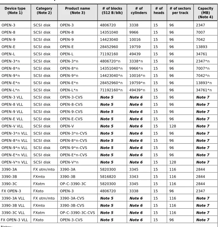
Table 1-2 lists the specifications for the logical devices on the Hitachi RAID storage systems. The sector size for the devices is 512 bytes.
Table 1-2 Device specifications Device type
(Note 1) Category (Note 2) Product name (Note 3) (512 B/blk) # of blocks cylinders # of heads # of # of sectors per track Capacity (MB) (Note 4) OPEN-3 SCSI disk OPEN-3 4806720 3338 15 96 2347 OPEN-8 SCSI disk OPEN-8 14351040 9966 15 96 7007 OPEN-9 SCSI disk OPEN-9 14423040 10016 15 96 7042 OPEN-E SCSI disk OPEN-E 28452960 19759 15 96 13893 OPEN-L SCSI disk OPEN-L 71192160 49439 15 96 34761 OPEN-3*n SCSI disk OPEN-3*n 4806720*n 3338*n 15 96 2347*n OPEN-8*n SCSI disk OPEN-8*n 14351040*n 9966*n 15 96 7007*n OPEN-9*n SCSI disk OPEN-9*n 14423040*n 10016*n 15 96 7042*n OPEN-E*n SCSI disk OPEN-E*n 28452960*n 19759*n 15 96 13893*n OPEN-L*n SCSI disk OPEN-L*n 71192160*n 49439*n 15 96 34761*n OPEN-3 VLL SCSI disk OPEN-3-CVS Note 5 Note 6 15 96 Note 7 OPEN-8 VLL SCSI disk OPEN-8-CVS Note 5 Note 6 15 96 Note 7 OPEN-9 VLL SCSI disk OPEN-9-CVS Note 5 Note 6 15 96 Note 7 OPEN-E VLL SCSI disk OPEN-E-CVS Note 5 Note 6 15 96 Note 7 OPEN-V VLL SCSI disk OPEN-V Note 5 Note 6 15 128 Note 7 OPEN-3*n VLL SCSI disk OPEN-3*n-CVS Note 5 Note 6 15 96 Note 7 OPEN-8*n VLL SCSI disk OPEN-8*n-CVS Note 5 Note 6 15 96 Note 7 OPEN-9*n VLL SCSI disk OPEN-9*n-CVS Note 5 Note 6 15 96 Note 7 OPEN-E*n VLL SCSI disk OPEN-E*n-CVS Note 5 Note 6 15 96 Note 7 OPEN-V*n VLL SCSI disk OPEN-V*n Note 5 Note 6 15 128 Note 7 3390-3A FX otm/mto 3390-3A 5820300 3345 15 116 2844 3390-3B FXmto 3390-3B 5816820 3343 15 116 2844 3390-3C FXotm OP-C-3390-3C 5820300 3345 15 116 2844 FX OPEN-3 FXoto OPEN-3 4806720 3338 15 96 2347 3390-3A VLL FX otm/mto 3390-3A-CVS Note 5 Note 6 15 116 Note 7 3390-3B VLL FXmto 3390-3B-CVS Note 5 Note 6 15 116 Note 7 3390-3C VLL FXotm OP-C-3390-3C-CVS Note 5 Note 6 15 116 Note 7 FX OPEN-3 VLL FXoto OPEN-3-CVS Note 5 Note 6 15 96 Note 7 Notes:
1. The availability of specific device types depends on the storage system model and the level of microcode installed on the storage system.
2. The category of a device (SCSI disk or Cross-OS File Exchange) determines its volume usage. SCSI disk devices (for example, OPEN-V) are usually formatted with file systems but can also be used as raw devices (for example, some applications use raw devices).
3. The product name for Virtual LVI/LUN devices is OPEN-x-CVS, where CVS = custom volume size. The command device (used for Command Control Interface operations) is distinguished by –CM on the product name (for example, OPEN-V-CM).
4. This capacity is the maximum size that can be entered. The device capacity can sometimes be changed by the BIOS or host adapter. Also, different capacities may be due to variations such as 1 MB = 10002 bytes or 10242 bytes.
5. The number of blocks for a Virtual LVI/LUN volume is calculated as follows:
# of blocks = (# of data cylinders) × (# of heads) × (# of sectors per track)
The number of sectors per track is 128 for OPEN-V and 96 for the other emulation types. Example: For an OPEN-3 VLL volume with capacity = 37 MB:
# of blocks = (53 cylinders – see Note 3) × (15 heads) × (96 sectors per track) = 76320
6. The number of data cylinders for a Virtual LVI/LUN volume is calculated as follows (↑…↑ means that the value
should be rounded up to the next integer):
§ Number of data cylinders for OPEN-x VLL volume (except for OPEN-V) =
# of cylinders = ↑ (capacity (MB) × 1024/720 ↑ Example: For OPEN-3 VLL volume with capacity = 37 MB: # of cylinders = ↑37 × 1024/720↑ = ↑52.62↑ = 53 cylinders
§ Number of data cylinders for an OPEN-V VLL volume =
# of cylinders = ↑ (capacity (MB) specified by user) × 16/15 ↑ Example: For OPEN-V VLL volume with capacity = 50 MB:
# of cylinders = ↑50 × 16/15↑ = ↑53.33↑ = 54 cylinders
7. The size of an OPEN-x VLL volume is specified by capacity in MB, not number of cylinders. The size of an OPEN-V VLL volume can be specified by capacity in MB or number of cylinders.
Host queue depth
Each operating system chapter in this document describes the specific
configuration files and file format syntax required to configure the queue depth settings on your Hitachi RAID storage systems. The requirements for host queue depth depend on the Hitachi RAID storage system model.
•
USP V/VM (and earlier). The Universal Storage Platform V/VM requires that the host queue depth (or max tag count) be set appropriately due to the queue depth limits of 32 per LUN and 2048 per port. This is because each MP in the USP V/VM can process a maximum of 4096 I/Os, and each MP manages two ports.•
VSP, HUS VM, VSP G1000. Due to the advanced architecture of the VSP, HUS VM, and VSP G1000, the I/O limit per MP in these storage systems has increased substantially. However, while the technical limit toqueue depth is much higher, the appropriate queue depth settings for each operational environment must be carefully researched and determined.
To ensure smooth processing at the ports and best average performance, the recommended queue depth setting (max tag count) for these storage systems is 2048 per port and 32 per LDEV. Other queue depth settings, higher or lower than these recommended values, can provide improved performance for certain workload conditions.
Caution: Higher queue depth settings (greater than 2048 per port) can
impact host response times, so caution must be exercised in modifying the recommended queue depth settings.
Host attachment workflow
1. Install the new Hitachi RAID storage system, or install the new physical storage devices on the existing Hitachi RAID storage system. This task is performed by the Hitachi Data Systems representative. See Installing the Hitachi RAID storage system.
2. Configure the Hitachi RAID storage system for host attachment. This task is performed by the Hitachi Data Systems representative and the user. See Configuring the Hitachi RAID storage system.
3. Configure the host for connection to the Hitachi RAID storage system, including host OS, middleware, and SNMP. This task is performed by the user. See Installing and configuring the host.
4. Install and configure the FC adapters for connection to the Hitachi RAID storage system. This task is performed by the user. See Installing and configuring the host FC adapters.
5. Connect the Hitachi RAID storage system to the host. This task is
performed by the Hitachi Data Systems representative and the user. See Connecting the Hitachi RAID storage system to the host.
6. Configure the newly attached hosts and LU paths. This task is performed by the user. See Configuring the new hosts and new LU paths.
7. Configure the new storage devices for use on the host. This task is performed by the user. See the following chapters:
– AIX® configuration and attachment – HP-UX configuration and attachment
– Red Hat Linux configuration and attachment – Solaris configuration and attachment
– SUSE Linux configuration and attachment – VMware configuration and attachment – Windows configuration and attachment – XenServer configuration and attachment
2
Preparing for host attachment
This chapter describes how to install and configure the Hitachi RAID storage system, host, and FCAs in preparation for host attachment.¨ Installation and configuration requirements ¨ Installing the Hitachi RAID storage system ¨ Configuring the Hitachi RAID storage system ¨ Installing and configuring the host
¨ Installing and configuring the host FC adapters
Installation and configuration requirements
Table 2-1 lists the requirements for installing and configuring the Hitachi RAID storage system for attachment to an open-systems host server.
Table 2-1 Installation and configuration requirements
Item Requirements
Hitachi RAID
storage system § The availability of features and devices depends on the Hitachi RAID storage system model and the level of microcode installed on the storage system. § The Hitachi Storage Navigator software must be installed and operational. For
details, see the Storage Navigator User Guide. For VSP G1000 see the Hitachi
Command Suite Administrator Guide.
§ The Hitachi LUN Manager feature must be enabled. For details, see the Storage Navigator User Guide. For VSP G1000 see the Hitachi Command Suite Administrator Guide.
Host server
hardware § Review the hardware requirements for attaching new storage to the host server. For details, see the user documentation for the host server. § For details about supported host server hardware, see the Hitachi Data
Systems interoperability site: http://www.hds.com/products/interoperability
Hardware for host
attachment § For details about supported hardware for host attachment (optical cables, hubs, switches, and so on), see the Hitachi Data Systems interoperability site:
http://www.hds.com/products/interoperability
Host operating
system § This document covers the following host platforms. Check the Hitachi Data Systems interoperability site for the latest information about host OS support. – AIX
– HP-UX – Red Hat Linux – Solaris – SUSE Linux – VMware – Windows – XenServer
§ Verify that the OS version, architecture, relevant patches, and maintenance levels are supported by the Hitachi RAID storage system. For details about supported OS versions, see the Hitachi Data Systems interoperability site:
http://www.hds.com/products/interoperability
§ Verify that the host meets the latest system and software requirements for attaching new storage. For details, see the host OS user documentation. § Verify that you have the host OS software installation media.
Item Requirements Host adapters
(HBAs and CNAs) § HBAs: The Hitachi RAID storage systems support FC HBAs equipped as follows: – 8-Gbps fibre-channel interface, including shortwave non-OFC (open fibre
control) optical interface and multimode optical cables with LC connectors. – 4-Gbps fibre-channel interface, including shortwave non-OFC (open fibre
control) optical interface and multimode optical cables with LC connectors. – 2-Gbps fibre-channel interface, including shortwave non-OFC (open fibre
control) optical interface and multimode optical cables with LC connectors. – 1-Gbps fibre-channel interface, including shortwave non-OFC optical
interface and multimode optical cables with SC connectors.
For OM3 fiber and 200-MB/s data transfer rate, the total cable length attached to each FC HBA must not exceed 500 meters (1,640 feet). Do not connect any OFC type connectors to the Hitachi RAID storage system.
§ CNAs: The Hitachi VSP storage system supports FCoE converged network adapters (CNAs) equipped as follows:
– 10 Gbps fibre-channel over Ethernet interface, including shortwave non-OFC (open fibre control) optical interface and multimode optical cables with LC connectors.
For OM3 fiber and 10-Gb/s data transfer rate, the total cable length attached to each CNA must not exceed 300 meters (984 feet). The diskless storage system model (no internal drives) does not support the FCoE option. Attachment to FCoE CNAs is supported for VMware and Windows hosts. § For details about installing the adapter and using the utilities and tools for the
adapter, see the user documentation for the adapter.
§ For details about supported host adapters and drivers, see the Hitachi Data Systems interoperability site: http://www.hds.com/products/interoperability
Storage area
network (SAN) § A SAN may be required to connect the Hitachi RAID storage system to the host. For details about supported fibre-channel switches, topology, and firmware versions for SAN configurations, see the Hitachi Data Systems interoperability site: http://www.hds.com/products/interoperability
Installing the Hitachi RAID storage system
The Hitachi RAID storage systems come with all hardware and cabling required for installation. The Hitachi Data Systems representative follows the
instructions and precautions in the Maintenance Manual for the storage system when installing the product. The installation tasks include:
•
Checking all specifications to ensure proper installation and configuration.•
Installing and assembling all hardware and cabling.•
Verifying that the Storage Navigator software is installed and ready for use. For details, see the Storage Navigator User Guide or for VSP G1000 theHitachi Command Suite Administrator Guide.
•
Installing and formatting the logical devices (LDEVs). The user provides the desired parity group and LDEV configuration information to the Hitachi Data Systems representative. For details, see the Provisioning Guide for the storage system (for USP V/VM see the manuals for LUN Manager, LUN Expansion, and Virtual LVI/LUN).Configuring the Hitachi RAID storage system
Complete the following tasks to configure the Hitachi RAID storage system for attachment to the host server:
¨ Setting the system option modes ¨ Configuring the ports
¨ Setting the host modes and host mode options
Setting the system option modes
To provide greater flexibility, the Hitachi RAID storage systems have additional operational parameters called system option modes (SOMs) that allow you to tailor the storage system to your unique operating requirements. The SOMs are set on the service processor by the Hitachi Data Systems representative. To set and manage the SOMs
1. Review the list of SOMs in the hardware guide for your storage system: – Hitachi VSP G1000 Product Overview, MK-92RD8051
– Hitachi VSP User and Reference Guide, MK-90RD7042
– HUS VM Block Module Hardware User Guide, MK-92HM7005
– Hitachi USP V/VM User and Reference Guide, MK-96RD635
– Hitachi USP/NSC User and Reference Guide, MK-94RD231
2. Work with your Hitachi Data Systems team to ensure that the appropriate SOMs for your operational environment are set on your storage system. 3. Check each new revision of the User and Reference Guide for SOM changes
that may apply to your operational environment, and contact your Hitachi Data Systems representative as needed.
Configuring the ports
Before the storage system is connected to the host, you must configure the ports on the Hitachi RAID storage system. Select the appropriate settings for each port based on the device to which the port is connected. The settings include attribute, security, speed, address, fabric, and connection type. For the latest information about port topology configurations supported by OS versions and adapter/switch combinations, see the Hitachi Data Systems
interoperability site: http://www.hds.com/products/interoperability
For details on configuring the ports, see the Provisioning Guide for the storage system (or the LUN Manager User’s Guide for the USP V/VM).
Note:
• If you plan to use LUN security, enable the security setting now before the port is attached to the host. If you enable LUN security on a port when host I/O is in progress, I/Os will be rejected with a security guard after LUN security is enabled.
• If you plan to connect different types of servers to the RAID storage system via the same fabric switch, use the zoning function of the fabric switch.
Setting the host modes and host mode options
Before the storage system is connected to the host, you must configure the host groups for the new hosts and set the host mode and host mode options (HMOs) for each host group. When you connect multiple server hosts of different platforms to a single port, you must group server hosts connected to the storage system by host groups that are segregated by platform. For example, if VMware hosts, Windows hosts, and Solaris hosts will be connected to a single port, you must create a host group for each platform and set the host mode and host mode options for each host group. Later when the storage system is connected to the hosts, you will register the new hosts in the
appropriate host groups.
While a host group can include more than one WWN, it is recommended that you create one host group for each host adapter and name the host group the same as the nickname for the adapter. Creating one host group per host adapter provides flexibility and is the only supported configuration when booting hosts from a SAN.
Table 2-2 lists and describes the host modes for the Hitachi RAID storage systems. Table 2-3 lists and describes the host mode options for the Hitachi RAID storage systems. For details and instructions on setting the host modes and host mode options, see the Provisioning Guide for the storage system (or the LUN Manager User’s Guide for the USP V/VM).
WARNING:
• Changing host modes or HMOs on a Hitachi RAID storage system that is already installed and attached to the host is disruptive and requires the host server to be rebooted.
• Before setting any HMO, review its functionality carefully to determine whether it can be used for your configuration and environment. If you have any questions or concerns, contact your Hitachi Data Systems
Table 2-2 Host modes for the Hitachi RAID storage systems
Host mode When to select this mode
00 Standard When registering Red Hat Linux, XenServer, or IRIX server hosts in the host group 01 VMware When registering VMware server hosts in the host group
When the host mode is 01 and an LU path is defined between the host group and a logical volume, the logical volume cannot be combined with other logical volumes to form a LUSE volume. If you plan to expand LUs by using LUSE in the future, set the host mode to 21 VMware Extension.
03 HP When registering HP-UX server hosts in the host group 05 OpenVMS When registering OpenVMS server hosts in the host group 07 Tru64 When registering Tru64 server hosts in the host group 09 Solaris When registering Solaris server hosts in the host group 0A NetWare When registering NetWare server hosts in the host group 0C Windows When registering Windows server hosts in the host group
When the host mode is 0C and an LU path is defined between the host group and a logical volume, the logical volume cannot be combined with other logical volumes to form a LUSE volume. If you plan to expand LUs by using LUSE in the future, set the host mode to 2C Windows Extension.
0F AIX When registering AIX server hosts in the host group 21 VMware
Extension When registering VMware server hosts in the host group When the host mode is 21 and an LU path is defined between the host group and a logical volume, the logical volume can be combined with other logical volumes to form a LUSE volume. If you plan to expand LUs by using LUSE in the future, set the host mode to 21 VMware Extension.
2C Windows
Extension When registering Windows server hosts in the host group When the host mode is 2C and an LU path is defined between the host group and a logical volume, the logical volume can be combined with other logical volumes to form a LUSE volume. If you plan to expand LUs by using LUSE in the future, set the host mode to 2C Windows Extension.
4C UVM When registering another storage system in the host group for mapping by using Universal Volume Manager.
If this mode is used when the storage system is being used as an external storage system of another storage system, the data of the MF-VOL in the storage system can be transferred. Refer to emulation types below for the MF-VOL.
The data of the MF-VOL cannot be transferred when the storage systems are connected with the host mode other than 4C UVM, and a message requiring formatting appears after the mapping. In this case, cancel the message requiring formatting, and set the host mode to 4C UVM when you want to transfer data.
The volume data of the following emulation types can be transferred: 3390-3A, 3380-3A, 3390-9A, 3390-LA.
Table 2-3 Host modes options for the Hitachi RAID storage systems
No. Host mode option When to select this host mode option
2 VERITAS Database
Edition/Advanced Cluster When VERITAS Database Edition/Advanced Cluster for Real Application Clusters or VERITAS Cluster Server 4.0 or later (I/O fencing function) is used. 6 TPRLO When all of the following conditions are satisfied:
§ The host mode 0C Windows or 2C Windows Extension is used. § The Emulex host bus adapter is used.
§ The mini-port driver is used.
§ TPRLO=2 is specified for the mini-port driver parameter of the host bus adapter.
7 Automatic recognition
function of LUN When all of the following conditions are satisfied: § The host mode 00 Standard or 09 Solaris is used.
§ SUN StorEdge SAN Foundation Software Version 4.2 or higher is used. § You want to automate recognition of increase and decrease of devices when
genuine SUN HBA is connected.
12 No display for ghost LUN When all of the following conditions are satisfied: § The host mode 03 HP is used.
§ You want to suppress creation of device files for devices to which paths are not defined.
13 SIM report at link failure1 When you want to be informed by service information message (SIM) that the
number of link failures detected between ports exceeds the threshold. 14 HP TruCluster with TrueCopy
function When all of the following conditions are satisfied: § The host mode 07 Tru64 is used.
§ You want to use TruCluster to set a cluster to each of P-VOL and S-VOL for TrueCopy or Universal Replicator.
15 HACMP When all of the following conditions are satisfied: § The host mode 0F AIX is used.
§ HACMP 5.1 Version 5.1.0.4 or later, HACMP4.5 Version 4.5.0.13 or later, or HACMP5.2 or later is used.
22 Veritas Cluster Server When Veritas Cluster Server is used.
23 REC Command Support1 When you want to shorten the recovery time on the host side if the data
transfer failed.
This HMO is not applicable to USP V/VM. 33 Set/Report Device Identifier
enable When all of the following conditions are satisfied: § Host mode 03 HP or 05 OpenVMS2 is used.
§ You want to enable commands to assign a nickname of the device. § You want to set UUID to identify a logical volume from the host. 39 Change the nexus specified
in the SCSI Target Reset When you want to control the following ranges per host group when receiving Target Reset: § Range of job resetting.
§ Range of UAs (Unit Attentions) defined. 40 V-VOL expansion When all of the following conditions are satisfied:
§ The host mode 0C Windows or 2C Windows Extension is used.
§ You want to automate recognition of the DP-VOL capacity after increasing the DP-VOL capacity.
41 Prioritized device recognition
No. Host mode option When to select this host mode option 42 Prevent "OHUB PCI retry" When IBM Z10 Linux is used.
43 Queue Full Response When the command queue is full in the storage system connecting with the HP-UX host, and if you want to respond Queue Full, instead of Busy, from the storage system to the host.
48 HAM Svol Read Option When you do not want to generate the failover from MCU to RCU, and when the applications that issue the Read commands more than the threshold to S-VOL of the pair made with High Availability Manager are performed.
This HMO is not applicable to VSP G1000.
49 BB Credit Set Up Option13 When you want to adjust the number of buffer-to-buffer credits (BBCs) to
control the transfer data size by the fibre channel, for example when the distance between MCU and RCU of the TrueCopy pair is long (approximately 100 kilometers) and the Point-to-Point topology is used.
Use the combination of this host mode option and the host mode option 50. 50 BB Credit Set Up Option23 When you want to adjust the number of buffer-to-buffer credits (BBCs) to
control the transfer data size by the fibre channel, for example when the distance between MCU and RCU of the TrueCopy pair is long (approximately 100 kilometers) and the Point-to-Point topology is used.
Use the combination of this host mode option and the host mode option 49. 51 Round Trip Set Up Option3 If you want to adjust the response time of the host I/O, for example when the
distance between MCU and RCU of the TrueCopy pair is long (approximately 100 kilometers) and the Point-to-Point topology is used.
Use the combination of this host mode option and the host mode option 65. 52 HAM and Cluster software for
SCSI-2 Reserve When a cluster software using the SCSI-2 reserve is used in the High Availability Manager environment. This HMO is not applicable to VSP G1000 and USP V/VM.
54 Support Option for the
EXTENDED COPY command When the VAAI (vStorage API for Array Integration) function of VMware ESX/ESXi 4.1 is used. 57 Conversion of sense
code/key Converts the sense code/key that is returned when an S-VOL is accessed. Apply this HMO when the sense code/key response needs to be converted when an old data volume of an HAM pair is accessed.
ON: Sense code/key 05/2500 (LDEV blockage) converted from 0b/c0000 is
returned when SSB=B8A0 is output.
OFF (default): Sense code/key 0b/c0000 is returned when SSB=B8A0 is
output.
This HMO is not applicable to VSP G1000 and HM700.
60 LUN0 Change Guard When HP-UX 11.31 is used, and when you want to prevent adding or deleting of LUN0.
This HMO is not applicable to USP V/VM. 61 Expanded Persistent Reserve
Key When 128 keys are insufficient for the host. This HMO is not applicable to USP V/VM. 63 Support Option for vStorage
APIs based on T10 standards When you connect the storage system to VMware ESXi 5.0 and use the VAAI function for T10. This HMO is not applicable to USP V/VM.
65 Round Trip extended set up
option3 If you want to adjust the response time of the host I/O when you use the host mode option 51 and the host connects the TrueCopy pair. For example, when
the configuration using the maximum number of processor blades is used. Use the combination of this host mode option and the host mode option 51. This HMO is not applicable to HM700 and USP V/VM.
No. Host mode option When to select this host mode option 67 Change of the ED_TOV value When the fibre channel port configuration applies to following:
§ The topology is the Fibre Channel direct connection. § The port type is Target or RCU Target.
This HMO is not applicable to USP V/VM. 68 Support Page Reclamation
for Linux When using the Page Reclamation function from the environment which is being connected to the Linux host. This HMO is not applicable to USP V/VM.
69 Online LUSE expansion When you want the host to be notified of expansion of LUSE volume capacity. This HMO is not applicable to VSP G1000 and USP V/VM.
71 Change the Unit Attention for
Blocked Pool-VOLs When you want to change the unit attention (UA) from NOT READY to MEDIUM ERROR during the pool-VOLs blockade. This HMO is not applicable to USP V/VM.
72 AIX GPFS Support When using General Parallel File System (GPFS) in the storage system connecting to the AIX host.
This HMO is not applicable to USP V/VM.
73 Support Option for WS2012 When using following functions provided by Windows Server 2012 (WS2012) from the environment which is being connected to the WS2012.
- Thin Provisioning function
This HMO is not applicable to USP V/VM. Notes:
1. Configure these host mode options only when requested to do so.
2. Set the UUID when you set host mode option 33 and host mode 05 OpenVMS is used. 3. Host mode options 49, 50, and 51 are enabled for the HF8G package.
Installing and configuring the host
This section describes general host configuration tasks that must be performed before the Hitachi RAID storage system is attached to the host server.
¨ Installing the host OS software ¨ Installing the LVM software ¨ Installing the failover software ¨ Installing the SNMP software
Note: The user is responsible for configuring the host system as needed for
the new storage devices.
• For assistance with host configuration, see the user documentation for the product or contact the vendor’s technical support.
• For assistance with specific configuration issues related to the Hitachi RAID storage system, contact the Hitachi Data Systems Support Center. For details, see Contacting the Hitachi Data Systems Support Center.
Installing the host OS software
The host operating system (OS) software must be loaded, configured, and operational before the Hitachi RAID storage system is attached.
1. Verify that the OS version, architecture, relevant patches, and maintenance levels are supported by the Hitachi RAID storage system. For details about supported OS versions, see the Hitachi Data Systems interoperability site: http://www.hds.com/products/interoperability
2. Verify that the host meets the latest system and software requirements for attaching new storage. For details, see the user documentation for the OS. 3. Verify that you have the host OS software installation media.
4. Verify that you have root/administrator login access to the host system.
Installing the LVM software
The Hitachi RAID storage systems support industry-standard products and functions that provide logical volume management (LVM). You must configure the LVM products on the host servers to recognize and operate with the new storage devices before the new storage is attached. For assistance with LVM operations, see the user documentation for the LVM software or contact the vendor’s technical support.
Installing the failover software
The Hitachi RAID storage systems support industry-standard products and functions that provide host, application, and path failover. You should
configure the failover products to recognize and operate with the new storage devices before the new storage is attached.
•
Supported host and application failover products include High Availability Cluster Multi-Processing (HACMP), Veritas Cluster Server, Sun Cluster, Microsoft Cluster Server (MSCS), and MC/ServiceGuard.•
Supported path failover products include Hitachi Dynamic Link Manager (HDLM), Veritas Volume Manager, DM Multipath, XenCenter dynamic multipathing, and HP-UX alternate link path failover.For assistance with failover operations, see the user documentation for the failover product or contact the vendor’s technical support.
For details about HDLM, see the HDLM User’s Guide for the host platform (for example, Hitachi Dynamic Link Manager User’s Guide for Windows), or contact your Hitachi Data Systems representative.
Note: Failover products may not provide a complete disaster recovery or
backup solution and are not a replacement for standard disaster recovery planning and backup/recovery.
Installing the SNMP software
The Hitachi RAID storage systems support the industry-standard simple network management protocol (SNMP) for remote storage system
management from the host servers. You must configure the SNMP software on the host before the new storage is attached. For assistance with SNMP
configuration on the host, see the SNMP user documentation or contact the vendor’s technical support.
SNMP is a part of the TCP/IP protocol suite that supports maintenance functions for storage and communication devices. The Hitachi RAID storage systems use SNMP to transfer status and management commands to the SNMP Manager on the host (see Figure 2-1). When the SNMP manager requests status information or when a service information message (SIM) occurs, the SNMP agent on the storage system notifies the SNMP manager on the host. Notification of error conditions is made in real time, enabling you to monitor the storage system from the open-systems host.
When a SIM occurs, the SNMP agent initiates trap operations, which alert the SNMP manager of the SIM condition. The SNMP manager receives the SIM traps from the SNMP agent and can request information from the SNMP agent at any time. Private LAN Error Info. Public LAN SNMP Manager Service
Processor Server Host SIM
Hitachi RAID storage system
Installing and configuring the host FC adapters
The host FCAs must be installed on the host before the Hitachi RAID storage system is attached. You also need to discover and write down the WWNs of the adapters to be connected to the storage system.
Note: The user is responsible for installing and configuring the adapters as
needed for the new storage devices.
• For assistance with host adapter configuration, see the user documentation for the adapter or contact the vendor’s technical support.
• For assistance with specific configuration issues related to the Hitachi RAID storage system, contact the Hitachi Data Systems Support Center. For details, see Contacting the Hitachi Data Systems Support Center. To install the host FC adapters:
1. Verify interoperability. Verify that the host adapters are supported by the Hitachi RAID storage system. For details, see the Hitachi Data Systems interoperability site: http://www.hds.com/products/interoperability
2. Install and verify the FCAs. Install the host adapters on the host server, and verify that the adapters are functioning properly. For details about installing the adapter and using the utilities for the adapter, see the user documentation for the adapter.
Note:
– Do not connect OFC-type FC interfaces to the Hitachi storage system. – If a switch or adapter with a 1-Gbps transfer rate is used, configure the
device to use a fixed 1-Gbps setting instead of Auto Negotiation. Otherwise, it may prevent a connection from being established.
However, the transfer speed of CHF port cannot be set as 1 Gbps when the CHF model type is 8US/8UFC/16UFC. Therefore 1-Gbps adapter and switch cannot be connected.
3. Configure the FCA. Use the setup utilities to configure the adapters to be connected to the Hitachi RAID storage system. The adapters have many configuration options. The minimum requirements for configuring the adapters for operation with the Hitachi RAID storage system are: – I/O timeout value (TOV). The disk I/O timeout value (TOV)
requirement for the Hitachi storage system is 60 seconds (0×3c hex). – Queue depth. The queue depth requirements for the Hitachi storage
system devices are listed below. You can adjust the queue depth for the devices later as needed (within the specified range) to optimize the I/O performance of the devices. For details, see Host queue depth.
Parameter for VSP G1000, VSP, HUS VM Recommended value Required value for USP V/VM Queue depth per LU 32 per LU ≤ 32 per LU
– BIOS. The BIOS may need to be disabled to prevent the system from trying to boot from the storage system.
Use the same settings and device parameters for all devices on the Hitachi RAID storage system. Several other parameters (for example, FC fabric) may also need to be set. Refer to the user documentation for the host adapter to determine whether other options are required to meet your operational requirements.
4. Record the WWNs of the FCAs. Find and write down the WWN of each
host adapter. You will need to enter these WWNs when you configure the new hosts on your storage system.
For details about finding the WWN of an adapter, see the user
documentation for the adapter. The method for finding the WWN varies depending on the adapter type, host platform, and topology. You can use the adapter utility (for example, the LightPulse Utility for Emulex), or the host OS (for example, the dmesg |grep Fibre command in Solaris), or the fabric switch connected to the host (for example, an AIX® host).
Connecting the Hitachi RAID storage system to the host
After the Hitachi RAID storage system and host have been configured, the Hitachi RAID storage system can be physically connected to the host system. Some of the steps in this procedure are performed by the Hitachi DataSystems representative, and some are performed by the user.
Note: The Hitachi Data Systems representative must use the Maintenance
Manual for the storage system during all installation activities. Follow all precautions and procedures in the Maintenance Manual, and always check all specifications to ensure proper installation and configuration.
To connect the Hitachi RAID storage system to the host system:
1. Verify the storage system installation. The Hitachi Data Systems representative verifies the configuration and operational status of the Hitachi RAID storage system ports, LDEVs, and paths.
2. Shut down and power off the host. The user shuts down and powers off the host. The power must be off when the FC/FCoE cables are connected.
3. Connect the Hitachi RAID storage system to the host system. The
Hitachi Data Systems representative connects the cables between the Hitachi RAID storage system and the host or fabric switch. Verify the ready status of the storage system and peripherals.
4. Power on and boot the host system. The user powers on and boots the host system after the storage system has been connected:
– Power on the host system display.
– Power on all peripheral devices. The Hitachi RAID storage system must be on, and the ports and modes must be configured before the host is powered on. If the ports are configured after the host is powered on, the host may need to be restarted to recognize the new settings. – Confirm the ready status of all peripheral devices, including the Hitachi
RAID storage system.
Configuring the new hosts and new LU paths
After discovering the WWNs of the host adapters and connecting the storage system to the host, you need to configure the new hosts and new LU paths on the Hitachi RAID storage system.
To configure the newly attached hosts and LUs:
1. Add new hosts. Before you can configure LU paths, you must register the new hosts in host groups. Register the new hosts in host groups using the WWNs of the host adapters. For details, see the Provisioning Guide for the storage system (LUN Manager User’s Guide for USP V/VM).
When registering hosts in multiple host groups, set the security switch (LUN security) to enabled, and then specify the WWN of the host adapter. 2. Configure LU paths. Configure the LU paths for the newly attached
storage devices, including defining primary LU paths and alternate LU paths and setting the UUID. For details, see the Provisioning Guide for the
storage system (LUN Manager User’s Guide for USP V/VM).
3. Set fibre-channel authentication. Set fibre-channel authentication as needed on host groups, ports, and fabric switches of the storage system. For details, see the Provisioning Guide for the storage system (LUN
Manager User’s Guide for USP V/VM).
After configuring the newly attached hosts and LUs, you are ready to configure the new storage devices for use on the host system. For details, see the
following chapters:
•
AIX® configuration and attachment•
HP-UX configuration and attachment•
Red Hat Linux configuration and attachment•
Solaris configuration and attachment•
SUSE Linux configuration and attachment•
VMware configuration and attachment•
Windows configuration and attachment•
XenServer configuration and attachment3
AIX
®
configuration and attachment
This chapter describes how to configure and manage the new Hitachi disk devices on an AIX® host:
¨ Hitachi storage system configuration for AIX® operations ¨ Verifying new device recognition
¨ Configuring the new devices
¨ Using the Object Data Manager with Hitachi RAID storage ¨ Online device installation
¨ Online LUSE configuration
Note: Configuration of the devices should be performed by the AIX® system
administrator. Configuration requires superuser/root access to the host system. If you have questions or concerns, please contact the Hitachi Data Systems Support Center.
Hitachi storage system configuration for AIX
®operations
The storage system must be fully configured before being attached to the AIX® host, as described in Configuring the Hitachi RAID storage system.Devices types. The following devices types are supported for AIX® operations. For details, see Device types.
•
OPEN-V•
OPEN-3/8/9/E/L•
LUSE (OPEN-x*n)•
VLL (OPEN-x VLL)•
VLL LUSE (OPEN-x*n VLL)•
Cross-OS File Exchange (FX) (3390-3A/B/C, OPEN-x-FXoto)Host mode. The required host mode for AIX® is 0F. Do not select a host mode other than 0F for IBM AIX. For a complete list of host modes, see Table 2-2. For details on setting host modes, see the Provisioning Guide for the storage system (or the LUN Manager User’s Guide for USP V/VM).
Host mode options. You may also need to set host mode options (HMOs) to meet your operational requirements. For a complete list of HMOs, see Table 2-3. For details on setting HMOs, see the Provisioning Guide for the storage system (or the LUN Manager User’s Guide for USP V/VM).