i
tif c n
e C
i o
c n
S f
l e
a r
n e
o n
i c
t e
a
2
nr 0
et 1
1
n I
ISC 2011
Proceeding of the International Conference on Advanced Science,
Engineering and Information Technology 2011
Hotel Equatorial Bangi-Putrajaya, Malaysia, 14 - 15 January 2011
ISBN 978-983-42366-4-9
ISC 2011
International Conference on Advanced Science, Engineering and Information Technology ICASEIT 2011
Cutting Edge Sciences for Future Sustainability
Hotel Equatorial Bangi-Putrajaya, Malaysia, 14 - 15 January 2011
SR
IE
AIV
UN IT NESIE DOKB
IN N
R AG
JA A
L S
A A
E N P M
N A
A L
U A T Y A S
S A I
REP
N I
NOI TAI COSSA STNEDUTS NA ISENOD
Organized by Indonesian Students Association Universiti Kebangsaan Malaysia
Proceeding of the
Effects of Open-Valve and Close-Valve Injections
on the Performance of a Port Injection Methane
Engine
Taib Iskandar Mohamad1, How Heoy Geok2,Shahrir Abdullah1 1
Department of Mechanical and Materials Engineering, Faculty of Engineering and Built Environment,
Universiti Kebangsaan Malaysia, 43600 Bangi, Selangor, Malaysia Tel.:+603-89216967, E-mail: [email protected]
2
Faculty of Engineering and Technology, Multimedia University, Jalan Ayer Keroh Lama, Bukit Beruang, 75450 Melaka, Malaysia.
Tel.:+606-252 3307, E-mail: [email protected]
1
Department of Mechanical and Materials Engineering, Faculty of Engineering and Built Environment,
Universiti Kebangsaan Malaysia, 43600 Bangi, Selangor, Malaysia Tel.:+603-89216013, E-mail: [email protected]
Abstract— Increasing concerns over energy security and stricter legislation on automotive exhaust emission limits have triggered greater efforts in utilizing alternatives to petroleum-based fuels. Compressed natural gas (CNG) is one of the promising candidates in terms of emissions and price. In this paper, methane, the major constituent of natural gas (NG), in used to fuel a Ricardo E6 engine and run in a port injection operation with open-valve and close-valve injection. The compression ratio is set at 10.5:1. Methane at 30 bar was supplied to the injector and injection length was adjusted to achieve the desired air fuel ratio (AFR). The minimum advance for best torque (MBT) was determined for 1100rpm speed by measuring the indicated mean effective pressure (IMEP) for
combustion at spark advance between 14oCA and 35oCA BTDC. The result is clearly demonstrated that the performance of the open
valve port injection (OVPI) is superior to the one of the close valve port injection (CVPI) with better IMEP, fuel conversion efficiency, indicated power and volumetric efficiency. The observation indicates that OVPI shows steadiness of peak pressures shifts toward top dead centre (TDC) as spark ignitions were advanced compared to CVPI. In terms of combustion characteristics, the OVPI operation yields shorter ignition delay and overall burning duration even at the same phasing angle. Therefore, the open valve operation is preferable for NG port injection due to the fact that injections take place while intake valve is open. It accelerates the charge flow into the cylinder causing higher volumetric efficiency and avoiding the back pressure that happen when high pressure methane is injected while intake valve closes.
Keywords— Methane, port injection, ignition timing, open-valve, close-valve.
I. INTRODUCTION
Increasing concerns over energy security and the emission of pollutant gases have triggered greater efforts to utilize alternatives fuels for road vehicles. In the presence of these concerns, automotive engine technology is challenged
liquefied petroleum gas (LPG), hydrogen, as well as ethanol and methanol. They are used either as supplement or replacement to gasoline in spark ignition engines. For compression ignition (CI) engines, dual fuel operation with diesel fuel providing pilot ignition source has been successful for heavy-duty applications. CI engines have also benefited from the use of various alternative fuels of vegetable origins as diesel replacement.
Natural gas use has various advantages over conventional fuels mainly due to its potential for higher thermal efficiency (due to higher octane value that allows the use of higher compression ratios), lower CO2 emission (due to lower carbon-to-hydrogen ratio) and less knocking tendency [5]-[8]. From the supply point of view, natural gas has the advantage of energy diversification and the total reserves have been estimated in the same order as petroleum but with only 60% of its production rate [9]. LPG is another promising alternative mainly due to its relatively high energy density, high octane rating and low pollutant emissions. It can be stored as liquid at moderate pressure, which gives it major advantage over most other alternative fuels. Methanol on the other hand has a very high octane rating but low heating value and stoichiometric AFR. Thus it leads to higher volumetric fuel consumption when compared to gasoline. Hydrogen fuel for electrically driven fuel cell cars, seen as the future replacement to internal combustion (IC) engine technology, is undergoing extensive research and development and is expected to be in large scale production at some distance of time. IC engine is therefore will remain
the key power source in the 21st century until fuel cell
vehicles become widespread [10].
The application of indirect fuel injection rather than carburetion has provided improvements in exhaust emissions and vehicle performance. This system introduces fuel at certain higher-than-ambient pressure, which provides more accurate control of fuel quantity injected. In addition, the absence of a venturi as in carburetor reduces intake system pressure reduction. There are mainly two type of indirect injection; single point and multipoint. The single point injection method uses an ECU-controlled fuel injector to introduce fuel into a mixer within the intake system. One common natural gas engine system utilizing this method is referred to GFI, which functions by introducing the expanded fuel to 7 bar into the intake manifold from a single injector nozzle [11]. In the multipoint injection or port injection method, fuel is injected into each intake manifold, where the numbers of fuel injector depends on the number of engine cylinder. This method has several advantages over single point injection including minimizing the risk of intake flashback and improving fuel distribution between cylinders [12]. In this system, NG is injected by individual injector at each cylinder intake manifold near the intake port just before the opening of intake valve. As a result, better control of mixture formation and response to changing speed can be achieved. Thus, it provides the opportunity to reduce the negative effects on the performance compared to carburettor-type or single injector manifold injection [8]. The objective of the paper is to investigate the effects of open-valve and close-valve injection on the performance of a port injection methane engine. The effect of varying the
ignition timings were also investigated and analyzed for both open and close-valve injection operations.
II. METHODOLOGY
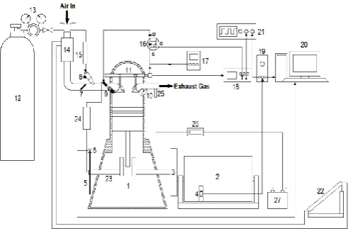
The methane port injection system was tested on a Ricardo E6 engine. Fig. 1 shows the schematic of the experimental set up. The engine is connected and mounted on a common test bed with a direct current electric dynamometer, which functions as motor or brake. Lubricant circulation is driven by an electric motor and water coolant is circulated by separately driven centrifugal pump. The engine has one intake and one exhaust poppet-type valves. A shaft encoder was mounted on the camshaft, giving one TTL signal per camshaft rotation which, corresponds to one signal for every two crankshaft rotations. The signal is set as an input to a pulse generator which output signal at changeable pulse length and delay is generated. This secondary signal which determines injector pulse length is then sent to a MOSFET that functions as a gate for the high power signal from power supply unit (12 V, 5A) to the fuel injector. Engine speed is controlled from the main unit of the electric dynamometer. Crank position is determined from the photodiode signals flashing through 180-rectangular-slotted disk mounted to the crankshaft.
Cylinder pressures were measured with an un-cooled type Kistler model 6121 A1 pressure sensor attached to the cylinder wall. Pressure signal is amplified through a piezoelectric amplifier. The crank angle and TDC were encoded using the photodiode and slotted disk system. Both crank angle and pressure signals were sent to a data acquisition system at 12000 samples per second rate. Methane is supplied from a 230 bar container and a pressure regulator is adjusted to achieved the desired injection pressures. Injection timings were varied to investigate the effects on engine performance. AFR was set to be stoichiometric and ignition timings were set at MBT. Methane was used as natural gas substitute due to close proximity of properties of these two gases.
There are two throttle valves available on the intake system with one fixed and another adjusted for varying air flow rate. Two injection timings were tested; open valve and closed valve. Methane at 30 bar was supplied to the injector and injection length was adjusted to achieve the desired AFR. The MBT was determined for 1100rpm speed by measuring the IMEP for combustion at spark advance
between 14oCA and 35oCA BTDC. The ignition timing was
1. Ricardo E6 engine, 2. Electric dynamometer, 3. Flywheel, 4. Load cell, 5. Slotted disk, 6. Photodiode, 7. Throttle valve, 8. Gasoline injector, 9. Spark plug, 10. Pressure sensor, 11. Camshaft and shaft encoder, 12. CNG tank, 13. Pressure
regulator, 14. Viscous air flow meter, 15. Fuel flow meter, 16. MOSFET circuit controller, 17. Power supply unit, 18. Pulse generator, 19. Charge amplifier, 20. Data acquisition controller, 21. Oscilloscope, 22. Multislope manometer, 23. Crankshaft, 24. Spark ignition unit, 25. Lambda sensor, 26. Lambda meter, 27. Battery
Fig. 1 Schematic of the experimental setup
TABLE I
SPECIFICATION OF RICARDO E6 ENGINE
Bore (mm) 76.2
Stroke (mm) 111.125
Displacement volume (cm3) 507
Compression ratio 10.5 : 1
Intake valve open 8o
CA BTDC
Intake valve close 33o
CA ABDC
Exhaust valve open 42o
CA BBDC
Exhaust valve close 8o
CA ATDC
Cooling method Water cooling
Valve clearance (intake/exhaust) 0.15 mm / 0.20 mm
III. RESULT AND DISCUSSION
The experimental investigations of methane port fuel injection in two modes; open valve and close valve were carried out. The method that yields the better performance between the two was selected as the basis of comparison with the performance of direct injection. The effects of varying the ignition timings on the overall performance are presented. The performances of comparison are IMEP, fuel conversion efficiency, indicated power and volumetric efficiencies. First, the effects of two fuel injections timings on performance were compared.
Fig. 2 through Fig. 7 show the results from OVPI and CVPI operations at 1100 rpm, stoichiometric AFR and 30 bar injection pressure at various ignition timings. In Fig. 2, for OVPI operation, cylinder pressures are plotted against crank angle for one cycle. The effect of spark advance can be seen from the values and timings of peak pressures. In Fig. 3, cylinder pressures are plotted against cylinder volume.
The area enclosed by the curve is the cyclic integral of pressures against volume which were used to determine indicated work and subsequently the IMEP. Fig. 4 shows the cylinder work over one cycle which represent positive work due to combustion during expansion process and negative work values due to compression process and combustion. Fig. 5 through Fig. 7 shows the same set of results for the CVPI.
Fig. 2 Cylinder pressures of OVPI at various spark advances
Fig. 3 PV diagram of OVPI at various spark advances
Fig. 5 Cylinder pressures of CVPI at various spark advances
Fig. 6 PV diagram of CVPI at various spark advances
Fig. 7 Cylinder work of CVPI at various spark advances
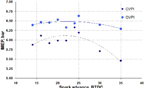
From Fig. 8 and Fig. 9, it is clearly demonstrated that the performance of OVPI is superior to the one of CVPI with overall higher IMEP and fuel conversion efficiency. In these figures, polynomial fit lines are drawn to show the trend of parameters change with different spark advances. Another observation is that OVPI shows steadiness of peak pressures shifts toward TDC as spark ignitions were advanced compared to CVPI. Volumetric efficiencies of OVPI also showed advantages over CVPI. These advantages were due to the fact that in OVPI operation, better air-fuel pre-mixture in the intake manifold was achieved because methane was injected into the flow of air. In the case of CVPI, methane occupies the inlet area and when the intake valve opens, the incoming flow of air pushes the bulk methane into the cylinder before further mixing inside the combustion chamber can happen.
Fig. 8 and Fig. 9 show that there are similar trends of performance change with varying spark timings where optimal calibration can be achieved. On average, the IMEP of OVPI operation is 7.7% higher than the one of CVPI. These result in better indicated power of 6.06% on average as shown in Fig. 10. The volumetric efficiencies of the two methods (Fig. 11) do not show significant difference due to the mass flow rate of air for both OVPI and CVPI operations are almost the same; with the average efficiency of OVPI is only 0.17% better. The average fuel conversion efficiency of CVPI and OVPI are 23.51% and 25.25% respectively. The difference gives OVPI an advantage of 7.42% more efficient.
The best ignition timings were found to be best at 24oCA
BTDC for CVPI and at 25 oCA BTDC for OVPI. At these
optimal setting, IMEP and indicated power differ by 1.54% and 1.71% respectively. The fuel conversion efficiency of OVPI is 1.55% better. Volumetric efficiency is the only advantage of CVPI with 75.01% compared to 74.87% in the OVPI. However, looking at the results, the OVPI operation produced a more stable performance over the whole range of tested spark timings especially at spark advances more than
25oCA BTDC as shown in Fig. 8 and Fig. 9. At these spark
advances, the performance drops in CVPI operation become
more obvious. The overall performance of OVPI operation
are no more than 10% better but more importantly, they are less effected by the variation of spark timing compared to CVPI operation. Because of these advantages, the OVPI was further investigated with the effects of ignition timing.
Fig. 8 IMEPs of OVPI and CVPI at various spark advances
Fig. 10 Indicated power of OVPI and CVPI at various spark advances
Fig. 11 Volumetric efficiencies of OVPI and CVPI at various spark advances
In addition, the combustion characteristics of both OVPI and CVPI were investigated. The characteristics were described by burning rate MBF is calculated by normalising the pressure rise due to combustion. It is assumed that the normalised pressure rise is directly proportional to the fraction of mass burnt [13], [14]. The most commonly used definitions for MBF profile is described as the followings [13].
1. Flame development angle, d. This is the interval
between spark event and the time when small but significant amount of fuel is burnt (about 10%), and referred as ignition delay.
2. Rapid burning angle, b. The interval when bulk of
fuel is burnt and bulk chemical energy released, typically the middle 10-90% of MBF curve.
3. Overall burning angle, o. The duration of overall
burning process, which is the sum of d and b.
Another useful parameter obtained from MBF
determination is the timing of the angle of maximum heat release, often referred to as combustion phasing angle and usually coincides with the 50% mass burnt fraction angle.
For most SI engines, this occurs between 5 oCA and 10oCA
ATDC.
Fig. 12 shows the MBF curve of the OVPI and CVPI at MBT. Injection timing has significant effect on the ignition
delay, d, which can be seen by the 18oCA in OVPI and
22oCA in CVPI. While the total combustion duration, o, is
24oCA for both. The difference of phasing angle, or the
angle were peak cylinder pressure (or 50% of burning) happens between the two methods results in the difference in
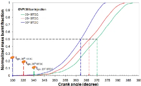
indicated performance (6oCA vs. 10oCA). Fig. 13 shows
MBF at three ignition times near MBT for the OVPI method. The shifts of combustion processes with respect to crank angle are in order with ignition advance. Combustion duration increases and ignition delay decreases as the
ignition is retarded. MBT was achieved at 25oCA BTDC
where 50% mass burnt point or the phasing angle is about 6o
ATDC. Table 2 shows the burning parameters for OVPI and CVPI operations.
TABLE 2
BURNING PARAMETERS FOR OVPI AND CVPI
Operations OVPI CVPI
Ignition delay angle, d 18o 22o
Rapid burning angle, b 24o 24o
Overall burning angle, o 42o 46o
From the combustion analysis, the OVPI operation yields shorter ignition delay and overall burning duration even at the same phasing angle. Therefore, the open valve operation is preferable for methane port injection due to the fact that injection while intake valve is opened. This helps accelerate the charge flow into the cylinder thus increasing volumetric efficiency and avoiding the back pressure that happen when high pressure methane is injected while intake valve closes which can reduces the amount of charge inhaled into the cylinder.
Fig. 12 Mass burnt fraction for OVPI and CVPI
IV. CONCLUSIONS
As conclusions, it is clearly demonstrated that the performance of OVPI is superior to the one of CVPI with overall higher IMEP, fuel conversion efficiency, power indicated and volumetric efficiency. The observation indicates that OVPI shows steadiness of peak pressures shifts toward TDC as spark ignitions were advanced compared to CVPI. In terms of combustion characteristics, the OVPI operation yields shorter ignition delay and overall burning duration even at the same phasing angle. Therefore, the open valve operation is preferable for NG port injection due to the fact that injection while intake valve is opened. This helps accelerate the charge flow into the cylinder thus increasing volumetric efficiency and avoiding the back pressure that happen when high pressure methane is injected while intake valve closes which can reduces the amount of charge inhaled into the cylinder.
NOMENCLATURE
ABDC After bottom dead centre
AFR Air fuel ratio
ATDC After top dead centre
BBDC Before bottom dead centre
BTDC Before top dead centre
CI Compressed ignition
CNG Compressed natural gas
CVPI Close valve port injection
ECU Electronic control unit
GFI Gaseous Fuel Injection
IMEP Indicated mean effective pressure
LPG Liquefied petroleum gas
MBT Minimum advance for best torque
MOSFET Metal-oxide-semiconductor field-effect
transistor
NG Natural gas
OVPI Open valve port injection
TDC Top dead centre
b Rapid burning angle
d Ignition delay angle
o Overall burning angle
ACKNOWLEDGMENT
The authors would like to acknowledge to Ministry of Science, Technology and Innovation (MOSTI) for sponsoring the research funding under project 03-01-02-SF0558.
REFERENCES
[1] C. Stan, Direct Injection Systems: The Next Decade in Engine
Technology, Warrendale, PA: SAE International, 2002.
[2] H. Bayraktar, and O. Durgun, “The effects of using gaseous fuels on
engine combustion and performance,” in The Sixth Combustion
Symposium, 1998, p. 273-285.
[3] T. Beer, T. Grant, D. Williams, and H. Watson, “Fuel-cycle
greenhouse gas emissions from alternative fuels in Australian heavy vehicles,” Atmospheric Environment, vol. 36, pp. 753-763, 2002.
[4] E. Johnson, “LPG: a secure, cleaner transport fuel? a policy
recommendation for Europe,” Energy Policy, vol. 31, pp. 1573-1577, 2003.
[5] S. Shiga, S. Ozone, H. T. C. Machacon, T. Karasawa, H. Nakamura,
T. Ueda, N. Jingu, Z. Huang, M. Tsue, and M. Kono, “A study of the combustion and emission characteristics of compressed-natural-gas direct-injection stratified combustion using a rapid-compression-machine,” Combustion and Flame, vol. 129, pp. 1-10, 2002.
[6] Z. Huang, S. Shiga, T. Ueda, H. Nakamura, T. Ishima, T. Obokata,
M. Tsue, and M. Kono, “Effect of fuel injection timing relative to ignition timing on the natural-gas direct-injection combustion,” Journal of Engineering for Gas Turbines and Power, vol. 125, pp. 783-790, 2003.
[7] H. M. Cho, and B.-Q. He, “Spark ignition natural gas engines - a
review,” Energy Conversion and Management, vol. 48, pp. 608-618, 2007.
[8] H. G. How, T. I. Mohamad, S. Abdullah, Y. Ali, A. Shamsudeen, and
E. Adril., “Experimental investigation of performance and emission of a sequential port injection natural gas engine,” European Journal of Scientific Research, vol. 30, pp. 204-214, 2009.
[9] A. K. Vourenkoski, “Development of a liquid-phase LPG MPI
conversion system,” PhD Thesis, Cranfield University, Cranfield, 2004.
[10] K. Morita, “Automotive power source in 21st century,” JSAE Review,
vol. 24, pp. 3-7, 2003.
[11] S. Carter, J. Heenann, and B. Williamson, “The GFI
system-prototype to product,” in 3rd International Conference on Natural
Gas Vehicles, 1992.
[12] J. C. Guibert, Fuels and Engines: Technology, Energy, Environment,
Paris: Institut Francais du Petrole Publication, 1999.
[13] J.B. Heywood, Internal Combustion Engines Fundamentals,
McGraw Hill, New York, 1988.
[14] G. M. Rassweiler, and L. Withrow, “Motion Pictures of Engines