TECHNICAL NOTE
SIZING OF A PACKED BED STORAGE FOR
SOLAR AIR HEATING SYSTEMS
K. Abbaspour-sani
Solar Energy Research Group, Department of Energy, Materials and Energy Research Center P. O. Box 14155-4777, Tehran, Iran, [email protected]
(Received: November 10, 2002 – Accepted: February 6, 2003)
Abstract Packed bed units generally, represent the most suitable storage units for air heating solar systems. In these systems the storage unit receives the heat from the collector during the collection period and discharges the heat to the building at the retrieval process. A method for sizing of packed-bed storage in an air heating system is represented. The design is based on the K-S curves, which have been generated for the storage used in the CSU solar House II through simulation. The complete simple solar heating system is simulated numerically during both the heating and retrieval processes. The simulation, which utilizes the hourly meteorological data, takes into account consideration of the principle parameters such as pressure drop across the bed, particle diameter, and mean voidage. The results are compared with the reported data from a real size of storage and also with the criteria of f-chart recommendation.
Key Words Packed Bed Storage, Air Heating Solar System, Simulation
ﻩﺪﻴﻜﭼ
ﻩﺪﻴﻜﭼ
ﻩﺪﻴﻜﭼ
ﻩﺪﻴﻜﭼ
ﻲﻣﻩﺩﺮﺸﻓﺮﺘﺴﺑﻉﻮﻧﺯﺍﻱﮊﺮﻧﺍﻩﺮﻴﺧﺫﻥﺰﺨﻣ،ﻲﻳﺍﻮﻫﻱﺪﻴﺷﺭﻮﺧﻱﺎﻫﻢﺘﺴﻴﺳﻢﻬﻣﻱﺍﺰﺟﺍﺯﺍﻲﻜﻳ
ﺪﺷﺎﺑ
.
ﻪﺑﺍﺮﻧﺁ ﺖﻓﺎﻳﺯﺎﺑﻡﺎﮕﻨﻫﻭﺖﻓﺎﻳﺭﺩﻱﺪﻴﺷﺭﻮﺧﻩﺪﻨﻨﻛﻊﻤﺟ ﺯﺍﺍﺭﺕﺭﺍﺮﺣ ،ﻱﮊﺮﻧﺍﺏﺬﺟ ﺪﻨﻳﺁﺮﻓﻲﻃﺭﺩﻥﺰﺨﻣ ﻦﻳﺍ
ﻲﻣﺮﻈﻧﺩﺭﻮﻣﻂﻴﺤﻣ ﺪﻧﺎﺳﺭ
. ﻥﺰﺨﻣﻦﻳﺍﺩﺎﻌﺑﺍﻦﻴﻴﻌﺗﻱﺍﺮﺑﻲﺷﻭﺭﻪﻟﺎﻘﻣﻦﻳﺍﺭﺩ
ﻱﺪﻴﺷﺭﻮﺧﻢﺘﺴﻴﺳﺭﺩﻩﺩﺎﻔﺘﺳﺍﺩﺭﻮﻣ
ﻲﻣﻪﺋﺍﺭﺍ ﺩﻮﺷ
.
ﻲﻨﺤﻨﻣ ﺱﺎﺳﺍﺮﺑﺵﻭﺭﻦﻳﺍ
ﻱﺪﻴﺷﺭﻮﺧﻢﺘﺴﻴﺳﻱﺯﺎﺳﻪﻴﺒﺷﻊﻗﻮﻣﺭﺩﻪﻛﻩﺩﻮﺑﻥﺰﺨﻣﺩﺮﻛﺭﺎﻛ ﻱﺎﻫ
ﻲﻣﺩﺎﺠﻳﺍ ﺩﺩﺮﮔ
. ﻱﺩﺪﻋﺵﻭﺭﻪﺑﻱﮊﺮﻧﺍﺖﻓﺎﻳﺯﺎﺑﻭﻱﺭﻭﺁ ﻊﻤﺟﺪﻨﻳﺁﺮﻓﻲﻃﺭﺩﻱﺪﻴﺷﺭﻮﺧﻪﻧﺎﺧﻚﻳﻞﻣﺎﻛﻢﺘﺴﻴﺳ
ﻪﻴﺒﺷ
ﻮﺟ ﺕﺎﻋﻼﻃﺍ ﻥﺁ ﻱﺩﻭﺭﻭ ﻪﻛ ﻩﺪﺷ ﻱﺯﺎﺳ
ّ
ﺗ ﻭ ﻱ
ﻪﻧﺎﺧ ﺐﺼﻧ ﻞﺤﻣ ﻱﺍﺮﺑ ﺖﻋﺎﺳ ﺮﻫ ﺭﺩ ﻱﺪﻴﺷﺭﻮﺧ ﺶﺑﺎ
ﻲﻣ ﻱﺪﻴﺷﺭﻮﺧ ﺪﺷﺎﺑ
.
ﻪﻴﺒﺷ ﻦﻳﺍ
ﻂﺳﻮﺘﻣﺮﻄﻗ ،ﺮﺘﺴﺑ ﻝﻮﻃﺭﺩ ﺭﺎﺸﻓﺖﻓﺍ ﻞﻴﺒﻗ ﺯﺍ ﻲﻠﺻﺍ ﻱﺎﻫﺮﺘﻣﺍﺭﺎﭘ ﻲﺧﺮﺑ ﻱﺯﺎﺳ
ﻲﻣﺮﻈﻧﺭﺩﺍﺭﻂﺳﻮﺘﻣﻞﺨﻠﺨﺗﻭﺎﻫﻪﻧﺍﺪﮕﻨﺳ ﺩﺮﻴﮔ
. ﻦﻳﺍﺭﺩﻩﺩﺎﻔﺘﺳﺍﺩﺭﻮﻣﻱﻮﮕﻟﺍﻥﻮﻣﺍﺮﻴﭘﺚﺤﺑﻦﻤﺿﻪﻟﺎﻘﻣﻦﻳﺍﺭﺩ
ﻪﻴﺒﺷ
ﻣﺁﺖﺳﺪﺑﺞﻳﺎﺘﻧ،ﻱﺯﺎﺳ
ﺵﻭﺭﺯﺍﻩﺪ
f-chart ﻪﺴﻳﺎﻘﻣﻲﻌﻗﺍﻭﻢﺘﺴﻴﺳﻚﻳﺩﺮﻜﻠﻤﻋﺯﺍﻩﺪﻣﺁﺖﺳﺪﺑﺕﺎﻋﻼﻃﺍﻭ
ﺪﻧﺍﻩﺪﺷ
.
1. INTRODUCTION
Packed bed units generally, represent the most suitable storage units for solar air heating systems where, the storage unit receives the heat from the collector during the collection period and discharges the heat to the building at the retrieval process. Two important considerations are involved in the design and operation of a packed - bed storage. Firstly, the rates of heat transfer that will take place between the airflow and solid particles is characterized by the volumetric heat transfer coefficient. Secondly, sizing of the bed involving determining, the four
most critical parameters: the airflow rate per unit of collector surface area, the equivalent particle diameter, the bed length, and finally, the bed frontal area. While the heat transfer within a packed bed associated with a solar heating system has been found in the literature [1,2,3] here, we deal with the second consideration.
collector surface, and the daily space-heating load must be adequately represented. Since these variations are irregular, a statistical approach to reflect all the possible considerations is desired.
One of the methodologies used in the design of a solar heating system is the f-chart method described by Beckman et al. [4]. In this method the results of many numerical experiments are correlated in terms of two dimensionless variables; one represents the monthly average heat loss from collector and other describes the monthly average absorbed solar energy as a function of monthly average total heating load. For a given solar heating system, the method provides a means to estimate the fraction of a total heating load that will be supplied by solar energy in respect to these variables. A number of different factors were taken into account in developing the design recommendation with the f-chart method and many simplifying assumptions
were necessary. Several reports on the design of storage for solar heating systems have been prepared [5,6]. It is recommended that one of the available calculation methods; the f-chart is used to Figure 1. Schematic diagram of a simple solar system.
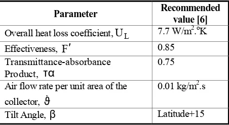
TABLE 1. Selected Design Parameter for Collector.
Parameter Recommended
value [6]
Overall heat loss coefficient,UL 7.7 W/m2.oK
Effectiveness, F′ 0.85
Transmittance-absorbance Product, τα
0.75
Air flow rate per unit area of the collector, ϑ&
0.01 kg/m2.s
determine the size of the collector. The volume of the storage device is assumed to be directly proportional to the collector area. The sizing of the storage, its surface area, and length are based directly on pressure drop considerations. The purpose of this paper is to present a simple method, yet accurate, for the design of the packed beds used for thermal storage in a simple heating system.
2. THERMAL MODEL OF THE SYSTEM
The design procedure developed in this study is based on the results obtained from the computer simulation of the solar heating system, shown in Figure 1. The system consists of a collector, a fan, a bypass controller for the retrieval process, and a packed bed storage unit.
Collector
The solid line in Figure 1 shows the path taken by the air during the collection and storing period. The path is a closed loop and the collector outlet temperature is dependent on the incident solar radiation and the storage outlet temperature. In the steady state the actual useful energy gain in collector described by following equation:
( )
(
)
[
L i a]
c R
u
F
A
I
U
T
T
q
=
τα
−
−
(1)Where, FR is the collector removal factor and is given
by [7]. ′ − = p L L p
R G C
F U exp 1 U C G F o
o (2)
Here, for simulation purposes the system parameters are associated with the collectors installed in the
CSU solar House II [7]. They are listed in Table 1.
Insolation
To estimate the insolation on the collector surface area during a time step, the simulation of the solar system requires hourly data. This is done using the meteorological data of the location of interest by the correlation of Erb et al. [8]. The results for calculating the monthly average daily total radiation on a horizontal surface are shown in Table 2.Packed Bed Storage
The air flows through the packed bed during the retrieval process in a counter-flow manner. The performance of the packed bed is described by Schumann model [1]. For common conditions encountered in solar applications, where the thermal conductivity of the bed in the flow direction compared to that in the perpendicular direction is very small, thus the Schumann model for this case is reduced to:( )
(
)
( )
p b( )
b v(
f b) ( ) (
s a b)
f b v f f p T T V UA T T h t T 1 C T T h x T A C m − + − = ∂ ∂ ε − ρ − = ∂ ∂ & (3) The volumetric heat transfer coefficient, hv, which
is a function of the flow rate through the bed is calculating using the correlation of Ergun [9]:
7 . 0 v dp G 650 h
= o (4)
Where
G
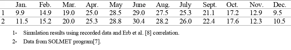
o is mass velocity per unit of frontal area of the bed and dp is the particle diameter.TABLE 2. Average Daily Total Radiation on a Horizontal Surface at Albquerque (Latitude 35.5o) in MJ/m2.
Jan. Feb. Mar. Apr. May June Aug. July Sept. Oct. Nov. Dec.
1 9.9 14.9 19.0 25.0 28.5 29.0 27.5 25.3 21.1 17.2 12.9 9.5
2 11.5 15.2 20.0 25.3 28.8 30.4 28.2 26.0 22.4 17.6 12.3 10.5
The physical properties of the storage medium, gravel, were considered to be constant. The mean
voidage,
ε
, greatly influences the pressure drop while it has less dramatic effect on the storage characteristics of the bed for a given length. A value of 0.35 was used in obtaining the data to be presented.Bypass Control
A bypass arrangement is necessary during the retrieval process, in order to maintain the temperature of the air delivered to the load and also the temperature of the air returning from the load was considered to be time independent and to have a constant prescribed value. It is assumed that the air circulation through the storage is terminated when the storage is no longer able to maintain the desired discharge temperature.3. SIMULATION
To simulate the solar heating system shown in Figure 1, Equation 1 and Equation 3 were solved numerically. The procedure followed in generating the results to be presented is as follows:
1. The meteorological data and design parameters associated with the collector and storage are selected. 2. The hourly insolation incident on the collector surface is calculated.
3. The monthly average insolation is computed. 4. A maximum pressure drop through the bed is selected.
5. For the initial mass velocity of the air, the length of the bed is calculated.
6. The monthly average energy supply during the retrieval process per unit area of the collector surface area is determined. This represents one point on the performance characteristics to be noted as K-S curves [10].
7. A new value of mass velocity is selected and steps 4-6 repeated until complete K-S curves are obtained. This procedure is repeated for each month of the year.
4. RESULTS AND DISCUSSION
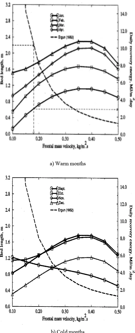
The performance of the solar system shown in Figure 1 was determined using the described procedure in Section 3. The pressure drop across the packed – bed storage bed was 0.76 Cm of water, the mean a) Warm months
b) Cold months
rock diameter was 2 Cm, and mean voidage of the bed was 0.35. For a given range of frontal mass velocity, calculation has been made for bed length and daily recovery energy. The results are shown in
Figure 2-a and 2-b in solid lines. These performance curves are referred to as K-S curves. The pressure drop across the packed bed is determined using the correlation of Ergun [9], which is defined by:
( )
( )
0.7f 3
f dp
1 150 G 75 . 1 dp 1 G g L
P
+ −εµ
ε ρ
ε − =
∆ (5)
The plot of this relation is shown as a dashed line in Figure 2-a and Figure 2-b. Once the bed length is selected, this plot can determine the mass velocity, G. The solid lines then determine the average daily energy retrieval for each month. The heating load and the retrieval rates are compared and the surface area of the collector is selected so best meets the heating load. The frontal area of the bed is:
o
&
G A v
A c f
f
ρ
= (6)
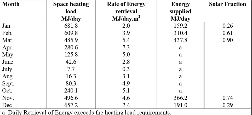
The results are shown in Table 2. The size of the collector is selected so that the system can meet the demand in March, and is found to be 79.6 Figure 3. The effect of mean voidage on variation of bed
length.
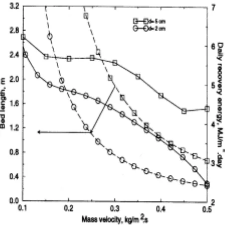
Figure 4. The effect of rock bed diameter on daily energy retrieval for solar heating system.
m2. By examining the energy supplied as
indicated in Table 2, it reveals that in some months auxiliary heating will be required. The frontal area of the storage unit using Equation 6 is found to be 5.72 m2. The total volume of the
storage bed is 12.6 m3 or 0.158 m3 /m2 of
collector surface area. In Table 4 some design data are compared with the reported data from a real size of storage unit and criteria of the f-chart recommendation.
Two variables, which were considered to be
primary importance in the design of the storage unit are the particle diameter and the total pressure drop through the bed. The effect of variations in these parameters on the performance characteristics was investigated. It is apparent from Equation 3 that the pressure drop is strongly influenced by the mean voidage of the bed. The effect of mean voidage on mass velocity is shown in Figure 3. Another significant variable in the design of a storage unit is the particle diameter. From Figure 4 it can TABLE 3. Load and Solar Energy Retrieval for Packed Bed Storage.
Month Space
heating
load
MJ/day
Rate of Energy
retrieval
MJ/day.m
2Energy
supplied
MJ/day
Solar Fraction
Jan.
Feb.
Mar.
Apr.
May
June
July
Aug.
Sept.
Oct.
Nov.
Dec.
681.8
609.8
485.9
280.6
125.8
42.6
7.7
16.3
80.3
240.1
496.6
657.2
2.0
3.9
5.4
7.3
5.0
2.8
0.3
3.1
4.9
5.1
4.6
2.4
159.2
310.4
437.8
a
a
a
a
a
a
a
366.2
191.0
0.26
0.61
0.90
0.74
0.29
a- Daily Retrieval of Energy exceeds the heating load requirements.
TABLE 4. Comparison of Design Data with the F-chart Recommendation and Reported Data.
Design data
Reported
data[5]
Predicted results
F-chart[6]
Collector flow rate per unit of surface
area, m
3/m
2.s
0.01 0.01
0.005-0.02
Storage capacity per unit of frontal
area, m
3/m
20.152 0.158
0.15-0.30
Pressure drop, Cm water
-
0.70 0.55-0.76
Mass velocity, kg/m
2.s
0.187
0.139
Min 0.0216
be seen that, for a bed with a given length, the mass velocity is increases with increasing of the particle diameter but it causes a decrease in heat transfer rate.
The effect of the maximum pressure drop across the bed on the sizing of the storage is shown in Figure 5. This indicates that if the allowable pressure drop is decreased, the bed must be shortened and the frontal area increased in order to obtain the same thermal characteristics for the system.
5. CONCLUSIONS
A simple method has been developed to design of packed bed storage for solar heating systems. The design is based on the K-S curves that have been generated for the storage used in the CSU solar House II through simulation. This simulation, which utilizes the hourly meteorological data, takes into account consideration the principle parameters such as pressure drop across the bed, particle diameter, and mean voidage.
The criteria based on the general design method (f-chart) reveals a satisfactory agreement between simulation results and reported data from real size storage. The proposed method should, however, be verified on a full-scale system either by the design and consideration of a unit for space heating or by modification of an existing unit to confirm the system previously described. It is obvious that the heat retrieval in the actual unit will be slightly less than the predicted value by the simulation, because the simulation ignored the air leakage and heat loss from the ducts connecting collector and storage. These losses can be greatly reduced by insulating the ducts.
6. NOMENCLATURE
A Surface area, m2
Cp Specific heat capacity, J/m2.K
dp Particle diameter, m
F′ Collector Efficiency factor FR Collector heat removal factor
g Gravitational acceleration, m/s2 h Heat transfer coefficient, J/m2.K
Go Mass flow rate per frontal area, kg/m2.s
L Bed length, m P Pressure, Pa T Temperature, oC
U Overall heat transfer coefficient, J/m2.K
τα Absorbance-Transmittance product
β Collector slope
ρ Density, kg/m3
µ Absolute viscosity, N.s/m2
Subscripts
A Ambient
b Bed column
f Fluid L Loss s Surface
v Volumetric
7. REFERENCES
1. Schumann, T. E. W., “A Liquid Flowing Through a Porous Prism”, In Solar Engineering of Thermal Processing, Duffie, J. A. and Beckman W. A., John Wiley, New York, (1991), 393-396.
2. Shewn, E. C., Sullivan, H. F., Hollands K. G. T. and Balakrishnar A. R., “A Heat Storage Sub-System for Solar Energy”, Tech. Rep. STOR-6, Waterloo Research Institute, University of Waterloo, Canada, (1978).
3. Shitzer, A. and Levy M., “Transient Behavior of a Rock- Bed Thermal Storage System Subjected to Variable Inlet Air Temperature: Analysis and Experimentation”, Trans. of ASME
J o u r n a l o f S o l a r E n er g y, Vol. 105, (1983),
200-206.
4. Beckman, W. A., Klein, S. A., and Duffie, J. A., “Solar Heating Design”, Wiley Inter-science, New York, (1977).
5. Cole, R. L., Nield, K. J., Rohde, R. R. and Wolosewics, R. M., “Design and Installation Manual for Thermal Energy Storage”, Tech. Rep. ANL-79-15, Argonne National Laboratory, US, (1985).
6. Duffie, J. A. and Beckman, W. A., “Solar Engineering of Thermal Processing”, John Wiley, New York, (1991). 7. Karaki, S. and Hawken, P., “Performance Evaluation of a
II”, Tech. Rep. COO-30122-27, Solar Energy Application Laboratory, Fort Collins, CO: CSU, (1982).
8. Erb, D. G., Klein, S. A. and Duffie, J. A., “Estimation of the Diffuse Radiation Fraction for Hourly, Daily, and Monthly-Average Global Radiation”, Solar Energy, Vol. 28, (1982), 293-299.
9. Ergun, S., “Fluid Flow through Packed-Bed Columns”,
Chem. Eng. Progr., (1952), 48.
10. Kulakowski, B. T. and Schmidt, F. W., “Discrete Control Algorithm for a Heat Storage System”, ASME Dynamic
System, Measurements, and Control, Vol. 102, (1980),