Please cite this article as: H. Nourghassemi, H. R. Taghva, D. Molyneux, H. Ghassemi, Numerical Hydrodynamic Performance of the Stepped Planing Craft and Its Step Height Effect, International Journal of Engineering (IJE), TRANSACTIONS A: Basics Vol. 32, No. 4, (April 2019) 602-607
International Journal of Engineering
J o u r n a l H o m e p a g e : w w w . i j e . i rNumerical Hydrodynamic Performance of the Stepped Planing Craft and Its Step
Height Effect
H. Nourghassemia, H. R. Taghvaa, D. Molyneuxb, H. Ghassemi*a
a Department of Maritime Engineering Amirkabir University of Technology, Tehran, Iran
b Department of Ocean and Naval Engineering, Memorial University of Newfoundland, St. John’s, Canada
P A P E R I N F O
Paper history:
Received 03 MAy 2018
Received in revised form 07 March 2019 Accepted 07 March 2019
Keywords:
Stepped Planing Craft Transverse Step Height Pressure Distribution Lift and Drag
A B S T R A C T
One of the most efficient methods of reducing drag on planing craft is the use of transverse step on the bottom of a hull. Applying steps on the hull reduces the contact area with water and as a result, it reduces drag of the craft. Planing craft are able to have one or two transverse steps. In this paper, numerical hydrodynamic performance of the stepped planing craft and its step height effect is investigated by making use of finite volume method (FVM). The Reynolds-Averaged Navier-Stokes (RANS) equations are coupled with the standard k- ε turbulence model and volume of fluid equations are solved to simulate transient turbulent free surface flow surrounding the hull by ANSYS-CFX. In order to predict the motion of the craft, equations of two degrees of freedom for rigid body are coupled with governing equations of fluid flow. In order to validate the numerical model presented in this paper, the obtained numerical results are compared with the available experimental data. The numerical results obtained for drag, dynamic trim, rising of center of mass and the pressure distribution on the body at different speeds and different heights of the steps are presented and discussed.
doi: 10.5829/ije.2019.32.04a.19
1. INTRODUCTION1
In recent decades, much effort is made by researchers to reduce drag and increase the speed of planing craft by changing the geometrical parameters of the hull. Various forms have been used so far, such as chine, strake, pad, spray rail, tunnel and step. Among these methods, applying transverse step on the hull is known as the most effective. It is common to create holes on the outer walls of the step for air suction. Generally, it is expected to increase the speed of craft by 10 to 15 per cent by applying stepping method2. All planing craft have control surfaces like trim-tab and interceptor. They are employed to semi-planing and planing craft to prevent the instability and improve seakeeping. In 1991, Maritime Dynamics, Inc. (MDI) pioneered the use of these devices as force producers to actively control the motions of mono-hulls and catamarans. Well over 100 MDI ride
*Corresponding Author Email: [email protected] (H. Ghassemi)
2
https://www.saltwatersportsman.com/stepped-hull-benefits-for-boats#page-3
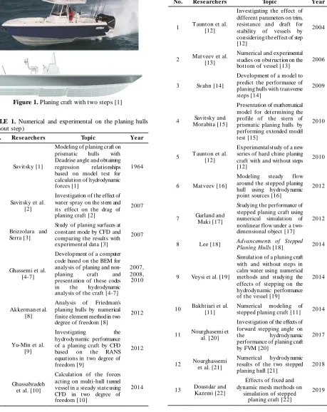
control systems incorporating trim tabs have been commissioned on fast ferries3. The main idea of applying transverse step on the hull is to reduce the level of contact of the hull with water and improve the running attitude. (see Figure 1). In this case, because of the force is distributed on two or three separate surfaces throughout the hull, the longitudinal stability is improved. However, despite the benefits of the transverse steps, there is also the risk of craft capsizing if the airway is closed by the coming waves. If aeration is stopped, reverse flow occurs behind the transverse step, which leads to an excessive increase in drag. As a result, the speed s uddenly decreases and the craft may capsize. To avoid this problem, air is often sucked through the duct above the water or is supplied through pipes on deck surface. So far, many numerical and experimental studies carried out on planing craft (with and without step). Numeric a l methods of the boundary element method (BEM) and
3 http://www.naiaddynamics.com
computational fluid dynamics (CFD) are mostly used for hydrodynamic analysis of the planing craft. Some of these studies are presented in Tables 1 and 2 for non -stepped and -stepped planing hulls, respectively.
Figure 1. Planing craft with two steps [1]
TABLE 1. Numerical and experimental on the planing hulls (without step)
No. Re se arche rs Topic Ye ar
1 Savitsky [1]
Modeling of planing craft on prismatic hulls with Deadrise angle and obtaining regression relationships based on model test for calculation of hydrodynamic forces [1]
1964
2 Savitsky et al. [2]
Investigation of the effect of water spray on the stern and its effect on the drag of planing craft [2]
2007
3 Brizzolara and Serra [3]
Study of planing surfaces at constant mode by CFD and comparing the results with experimental data [3]
2007
4 Ghassemi et al. [4-7]
Development of a computer code based on the BEM for analysis of planing and non-planing craft and presentation of these codes in the hydrodynamic analysis of the craft [4-7]
2007, 2008, 2010
5 Akkerman et al. [8]
Analysis of Friedman's planing hulls by numerical finite element method in two degree of freedom [8]
2012
6 Yu-Min et al. [9]
Investigating the hydrodynamic performance of a planing craft by CFD based on the RANS equations in two degree of freedom [9]
2012
7 Ghassabzadeh et al. [10]
Calculation of the forces acting on multi-hull tunnel vessel in a steady state using CFD in two degree of freedom [10]
2014
8 Bakhtiari et al. [11]
Numerical modeling of the stepped planing hull in calm water [11]
2016
TABLE 2. Numerical and experimental of the stepped planing hulls
No. Re se arche rs Topic Ye ar
1 T aunton et al. [12]
Investigating the effect of different parameters on trim, resistance and draft for stability of vessels by considering the effect of step [12]
2004
2 Matveev et al. [13]
Numerical and experimental studies on obstruction on the bottom of vessel [13]
2006
3 Svahn [14]
Development of a model to predict the performance of planing hulls with transverse steps [14]
2009
4 Savitsky and Morabita [15]
Presentation of mathematical model for determining the profile of the stern of prismatic planing hulls by performing extended model test [15]
2010
5 T aunton et al. [12]
Experimental study of a new series of hard chine planing craft with and without steps [12]
2010
6 Matveev [16]
Modeling steady flow around the stepped planing hull using hydrodynamic point sources [16]
2012
7 Garland and Maki [17]
Studying the performance of stepped planing craft using numerical simulation of nonlinear flow under a two-dimensional object [17]
2012
8 Lee [18] Advancements of Stepped
Planing Hulls [18] 2014
9 Veysi et al. [19]
Simulation of a planing craft with and without steps in calm water using numerical methods and studying the effects of stepping on the hydrodynamic performance of the vessel [19]
2014
10 Bakhtiari et al. [11]
Numerical modeling of stepped planing craft [11] 2014
11 Nourghasemi et al. [20]
Investigation of the effects of forward stepping angle on the hydrodynamic performance of planing craft by FVM [20]
2017
12 Nourghassemi et al. [21]
Numerical hydrodynamic results of the two stepped planing hull [21]
2018
13 Doustdar and Kazemi [22]
Effects of fixed and dynamic mesh methods on
simulation of stepped planing craft [22]
In this paper, the effect of height of step on the hydrodynamic performance of the planing craft is investigated by ANSYS-CFX software. Transient and turbulent free surface flow around the solid hull is modeled by the RANS equations along with the turbulence model standard k-ε coupled with VOF equations. To predict motion of the craft, equations of the two degrees of freedom of the rigid body are coupled with the equations governing the fluid flow. In this paper, the planing craft has two transversal steps. Here, six models are selected with various step height and three different displacements. The results of the numerica l results of drag, dynamic trim, raise of CG, pressure distribution are presented and discussed. Some numerica l results show good agreement with experimental data.
2. METHODOLOGY AND NUMERICAL
DESCRIPTION
The RANS solver is fully implicit, based on finite volume method to build the spatial discretization of the transport equations. The velocity field is obtained from the momentum conservation equations and continuity equation. In the case of turbulent flows, additional transport equations for modeled variables are discretized and solved. The k -ε turbulence model is used for turbulence closure. Free-surface flow is simulated with a multi-phase flow approach. Incompressible flow is modeled through the use of conservation equations for each volume fraction of phase/fluid. Velocity-pressure coupling is handled with a SIMPLE like approach. Craft free motion can be simulated with a 6-DOF module. Here in our case, 2-DOF (means pitching and heaving motions) are considered and other motions are fixed. In order to start the computation directly from a specific speed, an estimation of the final hull position is necessary. Estimation of the final position may be found from an assumption of the semi-empirical method, given by Savitsky [1]. In order to check the time step independency used the following equation:
𝐶𝐹𝐿 = (𝑑𝑡 × 𝑉)/𝑑𝑥 (1)
where CFL is the courant number and represents the number of cells that pass through by the current reference speed at the specified time step, dt is time step, V is current reference speed at the maximu m situation and dx is the average size of the cells. In order to achieve the time step independency, decrease both dt and dx so that the CFL stays constant. In the present computational method, the independence of the time step takes place at dt = 0.001.
2. 1. Computational Domain and Boundary Conditions The present study is conducted on a model of stepped planing craft, which is known as Lee model. This model was tested by Lee et al. [23] in 2014, and the results are available for public. The model was tested in six different step heights with specifications that are provided in Table 3. Besides, all of the models were tested and investigated at three displacements (or weight of planing craft) of 43.09, 47.62 and 55.38 kg. Geometrical parameters of the models are provided in Table 4. Besides, a two-dimensional view of the model is shown in Figure 2.
TABLE 3. Transverse step heights of the models
Mode l no. He ight of first ste p
[cm]
He ight of se cond ste p [cm]
1 0 0
2 0.3175 0.3175
3 0.635 0.3175
4 0.9525 0.3175
5 0.3175 0.635
6 0.635 0.635
7 0.3175 0.9525
TABLE 4. Characteristics of the model
Parameter Value
Length [m] 2
Width [m] 0.4572
Deadrise angle [deg] 15 Distance between the first step and stern
[m]
0.508
Distance between the second step and stern [m]
1.016
Displacement (∆)[kg] Variable
The flow around the craft can be assumed to be symmetric with respect to central plane. Therefore, calculations are reduced to only half of the solution domain. The distance between boundaries of this craft and the body are chosen in such a way that it is possible to apply boundary conditions that are consistent with reality.
The most important step in all numerical analyses is the grid generation. Grid type and element size have significant effect on convergence and accuracy. In this study, due to the use of k-ε turbulence model, the number of inflation layers within the boundary layer is considered equal to 22, and the dimensionless thickness of the first layer on the surface is Y + = 50.
In order to check the grid independency, calculations are performed in several grids with different numbers of cells. For example, the variation of drag at various number of cells for the model 4 at length Froude number (FnL=1.85) is illustrated in Figure 3.
3. RESULTS AND DISCUSSIONS
In this section, in order to validate the present numerica l model, the numerical results obtained for different heights of steps are presented and compared with experimental data. The craft model studied in this paper was tested by Lee et al. [23] for different heights of steps. The presented experimental results are included the raise of CG, dynamic trim, and drag for different displacements.
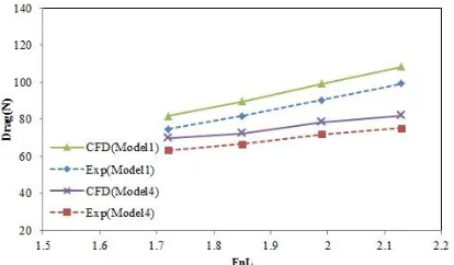
First, the numerical and experimental results for the model 1 (due to having the highest drag) and the model 4 (because of having the lowest drag) are presented in Figures 4 to 9. Another important is that drag is diminished around 20% by using step. Model 1 has no step and other six models have two steps. The results for all displacements showed that the stepped planing hulls have lower drag relative to non-stepped hull. The results were compared with experimental data for all models. These results are included drag, dynamic trim, the raise
Figure 3. M esh dependency for drag of the model 4 (FnL=1.85, ∆= 47.62 kg)
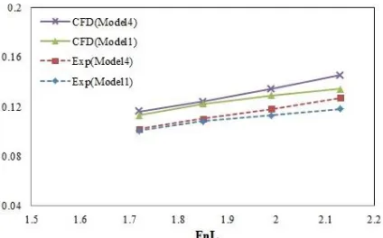
of CG/beam for different displacements. The comparison of drag against Froude numbers for three displacements are shown in Figures 4 and 5. Figures 6 and 7 present the dynamic trim results that are compared with the experimental data. The numerical results of the raise of CG/beam were also compared with experimental data that are shown in Figures 8 and 9. Relative errors were found that the raise center of CG/beam, dynamic trim and drag were less than 14, 15 and 10%, respectively.
The main aim to use the stepped planing craft is to provide the moderate pressure distribution. Figure 10 is presented the pressure contour on the bottom of different models at Fr= 2.13 and for ∆= 43.09 kg.
Figure 4. Comparison of drag r for models 1 and 4 (∆=
38.55 kg)
Figure 5. Comparison of drag for models 1 and 4 (∆=
47.62 kg)
Figure 6. Comparison of dynamic trim for models 1 and
Figure 7. Comparison of dynamic trim for models 1 and 4
(∆= 47.62 kg)
Figure 8. Comparison of the raise of CG/beam for models 1 and 4 (∆= 38.55 kg)
Figure 9. Comparison of the raise of CG/beam for models 1 and 4 (∆= 47.62 kg)
Stepped hull is caused that the pressure is moderately distributed from fore to aft. Without steps, a pressure peak is formed on the fore part of the hull. On the other hand, in the two-step planing craft, we have three peaks which increase the lift force on the body. It may be observed that the model 1 that has the highest drag, achieves the lowest level of pressure peak. In contrast, the model 4 has the lowest drag and highest level of pressure peak.
Figure 10. Pressure contour on the bottom of different models at Fr= 2.13, ∆= 43.09 kg.
4. CONCLUSIONS
In this paper, the effect of step height on the hydrodynamic performance of a planing craft is numerically investigated. For doing this, free surface flow around the craft is simulated using RANS equations coupled with Standard k-ε and VOF equations using ANSYS CFX. In order to predict the motion of craft in two degrees of freedom including heave and pitch, rigid body equations of motion are solved coupled with governing equations of fluid flow. According to the results, the following conclusions can be drawn:
According to the acceptable agreement between the results and experimental data, it can be inferred that the presented model can be used to predict hydrodynamic performance of planing craft with good accuracy.
Obviously, results indicate that adding steps to planing craft leads to reduction in drag. Because based on the obtained results for the desired models, model 1 without steps has the highest drag among the models. Besides, addition of steps leads to 4.6 to 20% reduction in drag.
Based on the obtained results for the desired models in three different displacements, it has been observed that the height of first step (from stern) is three times higher than the front step which has the lowest drag.
5. REFERENCES
1. Savitsky, D., "Hydrodynamic design of planing hulls", Marine Technology, Vol. 1, No. 1, (1964).
3. Brizzolara, S. and Serra, F., "Accuracy of cfd codes in the prediction of planing surfaces hydrodynamic characteristics", in 2nd International Conference on Marine Research and T ransportation., (2007), 147-159.
4. Ghassemi, H. and Ghiasi, M., "A combined method for the hydrodynamic characteristics of planing crafts", Ocean Engineering, Vol. 35, No. 3-4, (2008), 310-322.
5. Hassan, G. and Su, Y.-m., "Determining the hydrodynamic forces on a planing hull in steady motion", Journal of Marine Science and Application, Vol. 7, No. 3, (2008), 147-156.
6. KOHANSAL, A., GHASSEMI, H. and GHIASI, M., "Hydrodynamic characteristics of high speed planing hulls, including trim effects", Turkish Journal of Engineering and Environmental Sciences, Vol. 34, No. 3, (2011), 155-170. 7. Kohansal, A.R. and Ghassemi, H., "A numerical modeling of
hydrodynamic characteristics of various planing hull forms",
Ocean Engineering, Vol. 37, No. 5-6, (2010), 498-510. 8. Akkerman, I., Dunaway, J., Kvandal, J., Spinks, J. and Bazilevs,
Y., "T oward free-surface modeling of planing vessels: Simulation of the fridsma hull using ale-vms", Computational Mechanics, Vol. 50, No. 6, (2012), 719-727.
9. Su, Y., Chen, Q., Shen, H. and Lu, W., "Numerical simulation of a planing vessel at high speed", Journal of Marine Science and Application, Vol. 11, No. 2, (2012), 178-183.
10. Ghassabzadeh, M. and Ghassemi, H., "Determining of the hydrodynamic forces on the multi-hull tunnel vessel in steady motion", Journal of the Brazilian Society of Mechanical Sciences and Engineering, Vol. 36, No. 4, (2014), 697-708. 11. Bakhtiari, M., Veysi, S. and Ghassemi, H., "Numerical modeling of the stepped planing hull in calm water", International Journal of Engineering-Transactions B: Applications, Vol. 29, No. 2, (2016), 236-245.
12. T aunton, D., Hudson, D. and Shenoi, R., "Characteristics of a series of high speed hard chine planing hulls-part 1: Performance in calm water", International Journal of Small Craft Technology, Vol. 152, (2010), 55-75.
13. Matveev, K.I., "Three-dimensional wave patterns in long air cavities on a horizontal plane", Ocean Engineering, Vol. 34, No. 13, (2007), 1882-1891.
14. Svahn, D., "Performance prediction of hulls with transverse steps", A Report of Masters T hesis, T he Royal Institute of T echnology, KT H, Centre for Naval Architecture, (2009). 15. Savitsky, D. and Morabito, M., "Surface wave contours associated with the forebody wake of stepped planing hulls",
Marine Technology, Vol. 47, No. 1, (2010), 1-16. 16. Matveev, K.I., "T wo-dimensional modeling of stepped planing
hulls with open and pressurized air cavities", International Journal of Naval Architecture and Ocean Engineering, Vol. 4, No. 2, (2012), 162-171.
17. Garland, W.R. and Maki, K.J., "A numerical study of a two-dimensional stepped planing surface", Journal of Ship Production and Design, Vol. 28, No. 2, (2012), 60-72. 18. Lee, E.J., "Advancements of stepped planing hulls", Virginia
T ech, (2014),
19. Veysi, S.T .G., Bakhtiari, M., Ghassemi, H. and Ghiasi, M., "T oward numerical modeling of the stepped and non -stepped planing hull", Journal of the Brazilian Society of Mechanical Sciences and Engineering, Vol. 37, No. 6, (2015), 1635-1645. 20. Nourghasemi, H., Bakhtiari, M. and Ghassemi, H., "Numerical study of step forward swept angle effects on the hydrodynamic performance of a planing hull", Zeszyty Naukowe Akademii Morskiej w Szczecinie, (2017).
21. Nourghassemi, H., Ghassemi, H. and T aghva, H., "Numerical hydrodynamic results of the two stepped planing hull", American Journal of Mechanical Engineering, Vol. 6, No. 3, (2018), 93-97.
22. Doustdar, M.M. and Kazemi, H., "Effects of fixed and dynamic mesh methods on simulation of stepped planing craft", Journal of Ocean Engineering and Science, Vol. 4, No. 1, (2019), 33-48.
23. Lee, E., Pavkov, M. and McCue-Weil, L., "T he systematic variation of step configuration and displacement for a double-step planing craft", Journal of Ship Production and Design, Vol. 30, No. 2, (2014), 89-97.
Numerical Hydrodynamic Performance of the Stepped Planing Craft
and Its Step Height Effect
RESEARCH NOTE
H. Nourghassemia, H. R. Taghvaa, D. Molyneuxb, H. Ghassemia
a Department of Maritime Engineering Amirkabir University of Technology, Tehran, Iran
b Department of Ocean and Naval Engineering, Memorial University of Newfoundland, St. John’s, Canada
P A P E R I N F O
Paper history:
Received 03 MAy 2018
Received in revised form 07 March 2019 Accepted 07 March 2019
Keywords:
Stepped Planing Craft Transverse Step Height Pressure Distribution Lift and Drag
هدیکچ
هدافتسا .تسا روانش فک رد یضرع یاه هلپ زا هدافتسا یکسا یاهروانش رد گرد شهاک یارب دمآراک ورثوم یاهشور زا یکی
ود ای کی دنناوت یم یکسا یاهروانش .دوش یم گرد شهاک بجوم هجیتن رد و هندب هدش سیخ حطس شهاک ثعاب هلپ زا
مع یددع شور اب هلاقم نیا رد .دنشاب هتشاد یضرع هلپ شور اب هلپ عافتراریثات و راد هلپ یکسا روانش یکیمانیدوردیه درک
مجح تسا هتفرگ رارق یسررب دروم دودحم .
زدلونیر یریگ نیگنایم شور هب سکوتسا ریوان تلاداعم گتفشآ لدم اب
ی
درادناتسا k- ε سیسنا رازفا مرن کمک هب روانش هندب فارطا رد دازآ حطس یاهنایرج یزاس هیبش یارب CFX
هدش لح
.تسا ،یزاسربتعم تهج .دنا هدش لپوک مکاح تلاداعم اب یدازآ هجرد ود تکرح تلاداعم ،روانش تکرح ییوگشیپ روظنمب
.تسا هدش هسیاقم یبرجت جیاتن اب هدمآ تسدب یددع جیاتن تابساحم ،یکیمانید میرت ،گرد لماش هدمآ تسدب یددع جیاتن
دب یور راشف عیزوت ،مرج زکرم ندما لااب .تسا هدش ثحب و هئارا هلپ عافترا دنچ رد و فلتخم یاهتعرس رد هن
doi: 10.5829/ije.2019.32.04a.19