Please cite this article as: M. H. Shojaeefard, A. Khalkhali, S. O. Shahbaz, Low-Carbon Steel Sheet Asymmetric Single-Point Incremental Forming: Analysis and Optimization of the Surface Roughness, International Journal of Engineering (IJE), IJE TRANSACTIONS C: Aspects Vol. 32, No. 6, (June 2019) 866-871
International Journal of Engineering
J o u r n a l H o m e p a g e : w w w . i j e . i rLow-Carbon Steel Sheet Asymmetric Single-Point Incremental Forming: Analysis and
Optimization of the Surface Roughness
M. H. Shojaeefarda, A. Khalkhali*b, S. O. Shahbazb
a Department of Mechanical Engineering, Iran University of Science and Technology, Tehran, Iran
b Automotive Simulation and Optimal Design Research Laboratory, School of Automotive Engineering, Iran University of Science and Technology, Tehran, Iran
P A P E R I N F O
Paper history: Received 07 April 2019
Received in revised form 29 April 2019 Accepted 03 May 2019
Keywords:
Asymmetric Single-Point Incremental Forming Low-Carbon Steel Sheet
Surface Roughness Taguchi Technique
A B S T R A C T
Surface roughness (SR) has an adverse effect on the appearance of low-carbon steel parts, formed in the asymmetric incremental sheet forming (AISF) process, particularly those requiring painting operation. The purpose of this study is to investigate the effects of AISF process parameters on the surface roughness of an asymmetric part formed on low-carbon steel sheets. The parameters are feed rate, tool diameter, vertical step and spindle speed. Taguchi design of experiment (DOE) is used to investigate the process parameters effects and their interactions to achieve the minimum surface roughness. According to the obtained results, the roughness on the surface of low-carbon steel sheets is decreased during the asymmetric single-point incremental forming (ASPIF) due to a decrease in the vertical step and an increase in the tool diameter. In addition, the tool rotational speed and the feed rate have low effects on the surface roughness. The carried out validation test demonstrates that the Taguchi technique can effectively optimize the level of each input factor to ensure the best surface quality.
doi: 10.5829/ije.2019.32.06c.10
1. INTRODUCTION1
Asymmetric incremental sheet forming is utilized in rapid prototyping to produce prototypes or customized parts. In this way, the sheets are formed without a need for punches and related dies, in spite of being utilized in typical stamping processes. Therefore, AISF is a competitive alternative for economically manufacturing of low-volume productions. For instance, one application of this process can be found in the automobile industry for producing car body panels of concept vehicles or special cars which are formed on the low-carbon steel sheets. The process starts with incremental traveling of a forming tool into the sheet. The motion path is assumed to be characterized by G-codes in terms of Cartesian coordinates, derived from a computer-aided design and computer-aided manufacturing (CAD/CAM) software. Two methods of AISF are single-point incremental forming (SPIF) and two-point incremental forming (TPIF). SPIF (Figure 1(a)) was developed by Jeswiet and
*Corresponding Author Email: [email protected] (A. Khalkhali)
Hagan [1], Leach et al. [2], and Filice et al. [3] for the first time. In this type of AISF, a free, unsupported surface is detected on the back of the sheet that is being formed. Therefore, there would be just one point between the formed sheet and the tool tip. Powell and Andrew [4] and Matsubara [5] introduced the TPIF. In TPIF, as shown in Figure 1(b), there are two points to deform the metal sheet. One point, similar to the SPIF, is the forming tool that causes plastic deformation of the sheet. The other point is a full or partial die that locates under the sheet to facilitate the forming procedure, especially in forming of complex shapes.
Surface roughness control of the low-carbon or mild steel blanks is a critical requirement in the parts production by the ASPIF process. Roughness in the surface of mild steel sheets causes the orange peel phenomenon which is a textured imperfection in the painting process. Esthetic aspects of the painted mild steel samples disfigures by this imperfection. Therefore, it is important to analysis and optimize the roughness of the low-carbon steel sheets, formed by the ASPIF.
TECHNICAL NOTE
(a) (b)
Figure 1. (a) Single-point incremental forming (SPIF); (b) Two-point incremental forming (TPIF) [6]
However, previous studies have investigated the surface roughness of materials rather than low-carbon steel. Aluminium alloys are the material, used in almost all of the mentioned studies [7–16]. The stated literature failed to present a convincing and systematic method for analyzing and optimizing the whole process parameters on the surface roughness of low-carbon steel sheets in the ASPIF process. Application of the mild steels is becoming prevalent in different forming methods, including the asymmetric incremental forming, due to their interesting mechanical characteristics. Hence, surface roughness analysis and optimization seem to be necessary for these kinds of steel sheets in the ASPIF.
This research investigates the effects of main process variables on the surface roughness of low-carbon steel sheets, resulting from the asymmetric single-point incremental forming process of a car body panel production. Feed rate, tool diameter, vertical step and spindle speed are the main parameters of the experiments. By using a surface profile meter, thearithmetic average roughness (Ra) parameter is
considered to measure the surface roughness. Sixteen experimental tests are presented according to the design of experiments by means of Taguchi technique. The purpose is to study the effects of input factors to optimize the level of each parameter and obtain the minimum roughness of the low-carbon steel sheet in the ASPIF of a car body panel. Finally, the specimen results with the optimized parameters are confirmed by a validation experiment.
2. EXPERIMENTAL TESTS
2. 1. Material Properties The metal sheet used in
this study is DIN St12, a low-carbon steel sheet. Dimensions and thickness of the initial blanks are 250mm×160mm and 1mm, respectively. This material has good formability and high tensile strength. Mechanical properties and chemical composition of the St12 sheets are presented in Table 1.
2. 2. Experimental Tests Procedure The simplified
fender of NP01 (see Figure 2(a)), is assumed to be the part created on the initial blank. NP01 is the national automotive platform that is designed at the School of Automotive Engineering, Iran University of Science and Technology. In order to manufacture the fender using the ASPIF, some addendum surfaces should be added to the actual part. Due to asymmetric shape of the fender, the addendum surfaces facilitate a better tool movement on the blank and develop the shape by preventing the sheet failure, wrinkling, and tearing. Obviously, they are removed by a trimming operation at the end of the forming step. Limited workspace of the available 3-axes computer numerical control (CNC) milling machine with a Fanuc controller, leads to the fender dimensions downscale. The main dimensions of the fender with the addendum surfaces are shown in Figure 2(b).
The Tungsten Carbide forming tool, as shown in Figure 3(a), is characterized by a hemispherical tip. During sheet forming in the ASPIF, the tool tip wears and some small parts of the tool head may even become separated due to the local tool-sheet contact and the resulting friction between them. This has a negative effect on the forming surface quality. Hence, it is so important to choose an appropriate material with necessary strength for the tool to contact with the steel sheet. Generally, a Tungsten Carbide has a hardness value of about 1600 HV, while the hardness value of low-carbon steel is approximately 160 HV. Consequently, Tungsten Carbide is approximately wear-resistant when contacting the steel sheet and exhibits enough strength against friction and temperature increase during the forming process. The tip of the forming tool follows a Z-level path to form the fender based on the G-codes generated by the CAD/CAM software. The final formed blank (red fender in the center) is shown in Figure 3(b).
TABLE 1. Chemical composition and mechanical properties of St12 sheets utilized in the ASPIF process
Material Chemical Composition (wt%) Mechanical Properties
St12 C Mn P S YS UTS Elong. (%)
0.1 0.5 <0.05 <0.05 186 306 48
(a) (b)
(a) (b)
Figure 3. (a) Tungsten Carbide hemispherical forming tools used in the forming process of the mild steel sheets (mm); (b) Final fender of the NP01 formed on the low-carbon steel sheet
As an engineering optimization method, Taguchi introduces a useful technique for optimization of the characteristics of a desired performance by combining the influenced parameters. To obtain the best design state in terms of efficiency, quality, and total cost, the Taguchi method represents an effective method for attaining the finest parameters, resulting in robust and high quality systems. The tests are performed using a Taguchi design of experiments as a highly applicable technique for controlling the production quality. Input variables are the feed rate, tool diameter, vertical step and spindle speed. Surface roughness of the low-carbon steel sheet is assumed as the output parameter which is presented by Ra. Levels of the input parameters are shown in Table 2.
2. 3. Surface Roughness Measurement Main
elements of the surface topography in the AISF process are the surface waviness and surface roughness. During the ASPIF, when the tool moves on the sheet, certain areas on the blank remain as unforced regions because of the helical path of tool movement. Therefore, these sections lead to the surface waviness [17]. In addition, tool movement in a local zone on the blank during the ASPIF results in the surface roughness. In this study, surface roughness is denoted by the arithmetic average surface roughness (Ra). This parameter is established as
the average deviation of the surface irregularities over a specific length. In fact, Ra is integral of the roughness
height over the desired section of the part and is defined by Equation (1):
R |Y x |dx (1)
TABLE 2. Input parameters and their levels in the Taguchi design of experiments (4 factors in 4 levels)
Levels unit notation parameters L4 L3 L2 L1 250 215 185 150 mm/min F Feed rate 20 18 14 10 mm D Tool diameter 1 0.85 0.65 0.5 mm Z Vertical step 1000 840 670 500 rpm W Spindle speed
where Y is the ordinate of the roughness profile curve created on the formed blank during the process, and L is the sampling length in the part.
Microscopes, stylus instruments, or even a visual or feeling comparison with a standard comparator are used to assess the surface roughness in the industry. In this study, to determine the surface roughness of the formed blanks quickly and accurately, a Moore & Wright SURF SCAN 200, a stylus instrument, is applied.
3.RESULTS AND DISCUSION
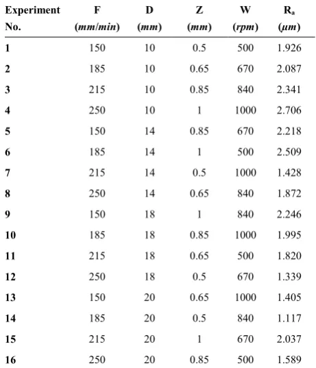
L16 Taguchi orthogonal array is adopted to investigate
how the four input variables affect the SR.Control factor values for each ASPIF experiment are shown in Table 3. For each experiment, the SR is measured in three different points in the internal surface of the fender and the average of all measured Ra is reported in Table 3 as
the sample roughness. The effect of input parameters on the output factor is shown in the means response table.
Table 4 is one of the most important tools of Taguchi technique to meet the objectives in an engineering design. The means response table can specify which process parameter has the largest impact on the response. In addition, the trend of each control factor can be observed. In other words, this table determines which level of the input variables is related to higher or lower response values. When the input parameters are changed,
TABLE 3. L16 Taguchi orthogonal array designed for the
roughness measurement on the mild steel sheets
Ra
(µm) W
(rpm) Z
(mm) D
(mm) F
TABLE 4. Response table for means of Ra in the ASPIF process of mild steel sheets
W Z
D F
Level
1.961 1.452
2.265 1.949
1
1.920 1.796
2.007 1.927
2
1.894 2.036
1.850 1.907
3
1.884 2.375
1.537 1.877
4
0.077 0.922
0.728 0.072
Delta
3 1
2 4
Rank
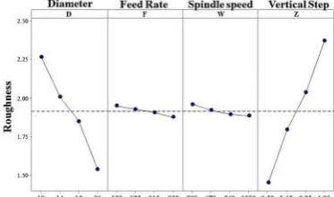
the response variations can be investigated using the main effect plot of the means. The means response table and the effect plot of means are illustrated in Figure 4 and Table 4. The ranks shown in Table 4 explain that the vertical step (Z), ranked first, is the most effective process parameter for the surface roughness of the formed blanks. The tool diameter (D) has the second highest effect on the surface roughness, which is followed by the spindle speed (W) and the feed rate (F), respectively.
An increase in the vertical step (Z) results in coarser surface roughness of the formed sheets. Table 4 depicts that Ra increases from 1.452 to 2.375µm over the step
depth range of 0.5 to 1mm (levels 1 to 4 in Table 1). By increasing the vertical step, the axial force of the tool increases and a deeper micro valley will occur on the surface of the mild steel sheet. Moreover, surface analysis of the samples showed that some regions of the sheet partially remained as micro peaks between the successive contours of each step in the tool vertical motion. Thus, micro peaks and valleys of the surface increase and lead to rougher surface. Reduction of the tool vertical movement results in a more overlap among the neighboring contour paths, traced by the forming tool. Consequently, increasing the tool steps in the vertical dimension increases the surface roughness in asymmetric single-point incremental forming of the low-carbon steel sheets; however, the process time reduces when the vertical step increases.
Figure 4. Main effect plots for means of Raof the mild steel sheets in the ASPIF experiments
An increase in the diameter of the tool (D) causes an appropriate effect on the surface roughness of the mild steel sheets. When the tool diameter size increases, Ra of
the final parts decreases. By using a bigger tool diameter, the contact pressure between the tool and the blank decreases and flattens the patterns (micro peak and valleys). As a result, the surface roughness will decrease. Furthermore, surface roughness reduction, by means of a larger tool diameter, can be ascribed to an increase in the overlap zones between each contours of the tool path; this is due to the larger contact area of the tool and the blank. Therefore, using a smaller diameter for the forming tool makes the surface of the low-carbon steel sheets rough; however, better formability occurs by means of an increase in the tool diameter size.
From Table 4 and Figure 4, it is inferred that by increasing the spindle speed (W), the surface roughness can be reduced (due to the selected range of the tool rotational speeds shown in Table 1). By speeding up the spindle, the sliding friction at the interface of the forming tool and the sheet increases. As a result, the heat treatment is increased in the forming process. In this way, contact area of the tool and the mild steel sheet is changed from adhesive to abrasive type and better surface quality is obtained. Moreover, the rotation tool creates some veins on the blank, which is the asperity of the surface. Increasing the spindle speed creates smaller veins, and the surface becomes more polished which illustrates a reduction in surface roughness of the mild steel sheets. As shown in Table 4, the spindle speed effect on the surface roughness of the ASPIF experiments is negligible.
When the feed rate increases in the ASPIF, Ra
decreases. In fact, higher feed rates associated with the tool vibration in the experiments result in increasing the wear rate, friction, and temperature. One reason is that when the feed rate increases, higher speed of the tool prevents the absolute formation of the lubricant film at the tool-blank interface. It can be concluded that the surface becomes rougher. However, in the present study, considering the specified feed rates, the results exhibit the contrary, showing that the lubricant film breakage occurs in the feeds more than those selected here. Increasing the feed rate in the selected range decreases the surface roughness of the mild steel sheets. Similar to the spindle speed, Table 4 shows that the feed rate has low effect on the surface roughness of this type of steel.
3. 1. Determination of the Optimum Surface
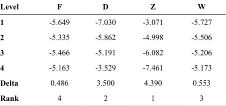
Roughness In Taguchi design, the signal-to-noise
constant nominal value, and the variance around this value is assumed as the noise factors; (2) the-smaller-the-better case, in which the occurrence of unfavorable characteristics of the final product is minimized; (3) the-larger-the-better case which is considered to maximize the output variable. This study aims to minimize the surface roughness; hence, the-smaller-the-better method is utilized based on Equation (2):
S/N ratio = −10 ∑
(2)
where yi is Ra, measured by the stylus instruments, and n
denotes the number of observations on a particular product. According to Table 5, the optimum level of the input variables (the largest S/N ratio), considering lower surface roughness on the formed low-carbon steel sheets, is D4F4W4Z1. It means the minimum Ra as the optimum
condition takes place when the fourth level of the tool diameter (D4), the fourth level of the feed rate (F4), the fourth level of the spindle speed (W4), and the first level of the vertical step (Z1) are selected. Based on Table 4, surface roughness rates at the levels of D4, F4, W4, and Z1 are 1.537, 1.877, 1.884, and 1.452 µm, respectively. The optimum Ra is predicted [18] as in the Equation (3):
Ra= D4+F1+W4+Z1-3T=1.537+1.877+1.884
+1.452 -3×1.914=1.008µm
(3)
3. 2. Validation Test To determine the error between the experimental tests and the mathematical modeling, a validation test was performed at a determined level. Accordingly, the best quality of the surface with the minimum roughness was determined based on the following conditions: the tool diameter of 20mm (D4: the fourth level of the tool diameter), feed rate of 250mm/min (F4: the fourth level of the feed rate), spindle speed of 1000rpm (W4: the fourth level of the spindle speed), and vertical step of 0.5mm (Z1: the first level of the vertical step). Respecting these input parameters, Ra of the experiment with factors of the
optimum condition is 1.083µm. The difference between the experimental test and the optimum predicted one is less than 7%. Hence, the optimum condition can be verified because of the small error between the experimental results and numerical prediction.
TABLE 5. Response table for the signal-to-noise ratios in the-smaller-the-better case
Level F D Z W
1 -5.649 -7.030 -3.071 -5.727
2 -5.335 -5.862 -4.998 -5.506
3 -5.466 -5.191 -6.082 -5.206
4 -5.163 -3.529 -7.461 -5.173
Delta 0.486 3.500 4.390 0.553
Rank 4 2 1 3
4. CONCLUSION
In this paper, the surface roughness of the low-carbon steel sheets, formed by the asymmetric single-point incremental forming was investigated. The effect of the process parameters, i.e., the feed rate, tool diameter, vertical step and spindle speed, was studied through the experimental tests. Arithmetic average roughness (Ra)
was employed to evaluate the effect of input variables on the roughness of the final formed blanks. The results of this study are as follows:
1. Vertical step has the highest important effect on the surface roughness of the mild steel sheets. Increasing the vertical step results in the increase of Ra and a
rough surface appears on the formed samples. 2. Increasing the tool diameter leads to reduction of Ra
and smoother surface of the low-carbon steel sheets in the ASPIF.
3. The spindle speed and the feed rate have no significant effect on the surface roughness of the mild steel sheets.
4. According to the graphs, tables and the provided experimental results, it was found that a better surface quality can be achieved with a lower vertical movement and a larger tool diameter.
5. The optimum condition characterized by the tool diameter of 20mm, feed rate of 250mm/min, spindle speed of 1000rpm and vertical step of 0.5mm is achieved by Taguchi technique and was experimentally validated.
5. REFERENCES
1. Jeswiet, J., and Hagan, E., “Rapid proto-typing of a headlight with sheet metal”, In 9th International Conference on Sheet Metal, Leuven, Belgium, (2001), 165–170.
2. Leach, D., Green, A.J., and Bramley, A. N., “A new incremental sheet forming process for small batch and prototype parts”, In 9th International Conference on Sheet Metal, Leuven, Belgium, (2001), 211–218.
3. Filice, L., Fratini, L., and Micari, F., “Analysis of Material Formability in Incremental Forming”, CIRP Annals, Vol. 51, No. 1, (2002), 199–202.
4. Powell, N. N., and Andrew, C., “Incremental Forming of Flanged Sheet Metal Components Without Dedicated Dies”, Proceedings of the Institution of Mechanical Engineers, Part B: Journal of
Engineering Manufacture, Vol. 206, No. 1, (1992), 41–47.
5. Matsubara, S., “Incremental backward bulge forming of a sheet metal with a hemispherical head tool-a study of a numerical control forming system II”, Journal of the Japan Society for
Technology of Plasticity, Vol. 35, No. 406, (1994), 1311–1316.
6. Silva, M. B., and Martins, P. A. F., “Two-Point Incremental Forming with Partial Die: Theory and Experimentation”, Journal
of Materials Engineering and Performance, Vol. 22, No. 4,
(2013), 1018–1027.
Engineers, Part B: Journal of Engineering Manufacture, Vol. 218, No. 10, (2004), 1307–1312.
8. Cerro, I., Maidagan, E., Arana, J., Rivero, A., and Rodríguez, P.P., “Theoretical and experimental analysis of the dieless incremental sheet forming process”, Journal of Materials
Processing Technology, Vol. 177, No. 1–3, (2006), 404–408.
9. Durante, M., Formisano, A., Langella, A., and Minutolo, F.M.C., “The influence of tool rotation on an incremental forming process”, Journal of Materials Processing Technology, Vol. 209, No. 9, (2009), 4621–4626.
10. Hamilton, K., and Jeswiet, J., “Single point incremental forming at high feed rates and rotational speeds: Surface and structural consequences”, CIRP Annals, Vol. 59, No. 1, (2010), 311–314. 11. Bhattacharya, A., Maneesh, K., Reddy, N.V., and Cao, J., “Formability and Surface Finish Studies in Single Point Incremental Forming”, Journal of Manufacturing Science and
Engineering, Vol. 133, No. 6, (2011), 621-627.
12. Lu, B., Fang, Y., Xu, D.K., Chen, J., Ou, H., Moser, N.H., and Cao, J., “Mechanism investigation of friction-related effects in single point incremental forming using a developed oblique roller-ball tool”, International Journal of Machine Tools and
Manufacture, Vol. 85, (2014), 14–29.
13. Echrif, S.B.M., and Hrairi, M., “Significant Parameters for the Surface Roughness in Incremental Forming Process”, Materials
and Manufacturing Processes, Vol. 29, No. 6, (2014), 697–703.
14. Gulati, V., Aryal, A., Katyal, P., and Goswami, A., “Process Parameters Optimization in Single Point Incremental Forming”,
Journal of The Institution of Engineers (India): Series C, Vol.
97, No. 2, (2016), 185–193.
15. Yao, Z., Li, Y., Yang, M., Yuan, Q., and Shi, P., “Parameter optimization for deformation energy and forming quality in single point incremental forming process using response surface methodology”, Advances in Mechanical Engineering, Vol. 9, No. 7, (2017), 1–15.
16. Taherkhani, A., Basti, A., Nariman-Zadeh, N., and Jamali, A., “Achieving maximum dimensional accuracy and surface quality at the shortest possible time in single-point incremental forming via multi-objective optimization”, Proceedings of the Institution of Mechanical Engineers, Part B: Journal of Engineering
Manufacture, Vol. 233, No. 3, (2019), 900–913.
17. Shojaeefard, M. H., Khalkhali, A., and Shahbaz, S., “Analysis and optimization of the surface waviness in the single-point incremental sheet metal forming”, Proceedings of the Institution of Mechanical Engineers, Part E: Journal of Process
Mechanical Engineering, (2018), 1–7.
18. Ross, P.J., “Taguchi techniques for quality engineering: loss function, orthogonal experiments, parameter and tolerance design”, McGraw-Hill: New York, (1988).
Low-Carbon Steel Sheet Asymmetric Single-Point Incremental
Forming: Analysis and Optimization of the Surface Roughness
M.H. Shojaeefarda, A. Khalkhalib, S.O. Shahbazb
a Department of Mechanical Engineering, Iran University of Science and Technology, Tehran, Iran
b Automotive Simulation and Optimal Design Research Laboratory, School of Automotive Engineering, Iran University of Science and Technology, Tehran, Iran
P A P E R I N F O
Paper history: Received 07 April 2019
Received in revised form 29 April 2019 Accepted 03 May 2019
Keywords:
Asymmetric Single-Point Incremental Forming Low-Carbon Steel Sheet
Surface Roughness Taguchi Technique
!" #$ % & '( . *(+
, + - .
/ 0& (1 23 4 , + - . & .2
5& 6 7 8 #$ % & .2 9:3 " 23 ;<. - .
, %- 5=
>6 > ;" ?& -" .2 *(+ * @- 5 4 5& 4 9:3 5 # (
7 & .( & $
#=<A - . 2B1 ?& -" #B& % .(" (" & < 1 4 " ;<. 23 # 2 +
*( ?& -" 4<"
#=<A C - > ;" (3 *(+ #=<A . D E 1 #
doi: 10.5829/ije.2019.32.06c.10
![Figure 1. (a) Single-point incremental forming (SPIF); (b) Two-point incremental forming (TPIF) [6]](https://thumb-us.123doks.com/thumbv2/123dok_us/19062.2001994/2.595.60.286.100.200/figure-single-point-incremental-forming-spif-incremental-forming.webp)