Development of Flexible Pneumatic Cylinder
with Backdrivability and Its Application
Takafumi Morimoto,
Mohd Aliff, Tetsuya Akagi, and Shujiro Dohta
Department of Intelligent Mechanical Engineering, Okayama University of Science, Okayama, Japan Email: {t14rm08mt, t13sd02ma}@ous.jp, {akagi, dohta}@are.ous.ac.jp
Abstract—In the remote controlled rehabilitation device, physical therapists must recognize the situation of the patient. The actuator in the device is also required to be flexible so as not to injure the body. In our previous study, the flexible pneumatic cylinder was proposed and tested. The flexible robot arm using the cylinders for human wrist rehabilitation was also developed. In the next step, it is necessary to develop the master device for bilateral master-slave control. In this paper, the flexible pneumatic cylinder with backdrivability for bilateral control is proposed and tested. The performance of the tested cylinder is also investigated. After that, the master robot arm using the tested flexible cylinders is proposed and constructed.
Index Terms—flexible pneumatic cylinder, backdrivability, flexible robot arm, rehabilitation device, bilateral control
I. INTRODUCTION
The percentage of elderly continues to rise while the number of the newborn is kept decreasing. This makes a problem to take care of the elderly. The problem becomes worst when the society and the government failed to provide appropriate infrastructure to the aged and the disabled persons. This problem is also encountered in Japan. The aged over 65 years old in Japan accounted for 24.1% from the total of population on 2012 [1]. Recently, many studies have shown that the robot can be used in the medical field such as giving caregivers the extra strength which they need to lift patients [2] and also can be used in complex surgery [3]. In healthcare, robot can be used to assist in nursing care and also can support the activities of daily living for people with disabilities [4]. It must also have safety features such as not harming users and must have a flexible structure so as to be used in contact with human body [5]. In recent years, many lightweight actuators had been studied and developed. The materials for the actuator have been also studied to produce a wearable actuator [6]. Cost to produce an actuator and robot must be also taken into account. So far we have proposed and tested the new types of the flexible pneumatic actuator using low-cost embedded controller in our laboratory [7]. The flexible robot arm has been also proposed and tested in our studies for rehabilitation of human wrist [8]. This robot arm with simple structure by using flexible pneumatic cylinders has three degree-of-freedom that are bending, expanding and contracting. The
Manuscript received April 11, 2014; revised June 16, 2014.
master-slave control is adopted into the robot arm as a control method in order to be used in the rehabilitation field. In this paper, first, the construction and operating principle of the flexible pneumatic cylinder and robot arm are explained briefly. And the master-slave control system of the robot arm is also described. Then, the flexible pneumatic cylinder that has five motions such as “push”, “pull”, “lock”, “reset” and “free” modes is proposed. Finally, we introduce the flexible robot arm with backdrivability for bilateral master-slave control.
II. FLEXIBLE PNEUMATIC CYLINDER AND ROBOT ARM
A. Flexible Pneumatic Cylinder
In our previous study, two types of novel rod-less type flexible pneumatic cylinder had been developed [7]. Fig. 1 (a) and (b) show the constructions of the cylinder which (a) is a “Single ball type” and (b) is a “Double ball type”. Both types have the similar construction and the same operating principle. The difference of their properties is as follows. The single ball type has less frictional force because of less contracted area between the tube and the ball. The double ball type has higher flexibility for bending around the slide stage because of thinner slide stage. The single ball type cylinder consists of a flexible tube as a cylinder and gasket, one steel ball as a cylinder head and a slide stage that can slide along the outside of the tube. The steel ball is pinched by two pairs of brass rollers from both sides of the ball. The operating principle of the flexible pneumatic cylinder is as follows. When the supply pressure is applied to one side of the cylinder, the inner steel ball is pushed. At the same time, the steel ball pushes the brass rollers and then the slide stage moves while it deforms the tube. The minimum driving pressure of the double ball type cylinder is 130kPa and single ball type is 120kPa [7].
Steel ball (9mm)
Brass roller (Φ4mm)
Steel balls (3mm)
) Flexible tube
Φ
D
Duralumin plate(3mm
8 12
W
Steel balls (9mm)
Brass roller (Φ4mm)
Steel balls (3mm)
Duralumin plate(3mm) Flexible tube
ΦD
(b) Double ball type
Figure 1. Construction of flexible pneumatic cylinder.
B. Flexible Robot Arm
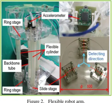
Fig. 2 shows the flexible robot arm using single ball type flexible pneumatic cylinders. The robot arm consists of two round stages and three flexible pneumatic cylinders that include three slide stages and flexible cylinders. The outer diameter of the upper and lower stage is 100mm and the initial distance between the upper and lower stage is about 100mm. Each flexible pneumatic cylinder is arranged so that the central angle of two adjacent slide stages becomes 120 degrees on the stage. An end of each flexible cylinder is fixed in the upper stage. The robot arm has the outer diameter of 100 mm and the length of 250 mm. The total mass of the robot arm is 380g. The operating principle of the flexible robot arm is as follows. When the pressure is supplied on the three top ends of the cylinders, the robot arm will expand or move upward. On the other hand, the robot arm will contract or move downward when the pressure is supplied on the three bottom ends of the cylinders. The bending motion of the arm can be obtained as follows. When one cylinder is fixed by pressurizing at both ends and other two cylinders are pressurized at the bottom ends only, two cylinders are contracted and consequently the robot arm is bent toward opposite side of the fixed cylinder. Thus, by controlling the pressure to each cylinder, the robot arm can be bent to every direction.
Figure 2. Flexible robot arm.
In our previous study [8], we had developed master slave control system using the above flexible robot arm. Fig. 3 shows the schematic diagram of the master-slave control system. The slave arm consists of the tested robot arm, an accelerometer, the embedded controller (Renesas Co. Ltd., SH7125) and six quasi-servo valves [9]. The master arm consists of an accelerometer and a flexible
tube with a round stage as shown in the left photo in Fig. 3. The master-slave control was executed by using the previous control system [10]. In the experiment, the slave arm could trace the movement of the master arm by using the control scheme based on the analytical model of the robot arm. We confirmed the validity of the control system and the usefulness of the robot arm for the rehabilitation device. However, the proposed method has a deficiency that the physical therapist (master arm) can not recognize the force from the slave arm which is held by the patient. Therefore, it is required to develop the master arm which can recognize the reaction force from the slave arm in order to avoid any injure during the rehabilitation process.
Figure 3. Master slave control system.
III. FLEXIBLE PNEUMATIC CYLINDER WITH BACKDRIVABILITY
A. Construction
Figure 4. Construction of tested flexible pneumatic cylinder.
stages connected with each other. Two tubes are set on parallel with a distance of 20 mm. Each steel ball is placed in each cylinder tube on the opposite side so that it can make the cylinder move upward or downward and also can clamp the slide stage during the “lock” mode. The size and the inner construction of each slide stage are same as previous one as shown in Fig. 2. In order to reduce the friction, it is coated with the grease in the tube.
B. Operating Principle
(e) “free” mode
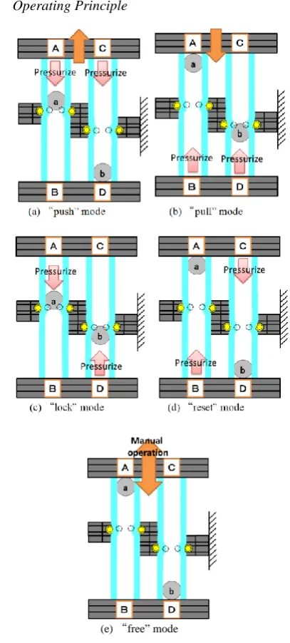
Figure 5. Operating principle of the tested cylinder.
Figs. 5 (a) to (e) show the operating principle of the tested flexible pneumatic cylinder for each motion. During the operation, the cylinder is driven while the slide stage is fixed. The tested cylinder has five motions such as “push”, “pull”, “lock”, “reset” and “free” modes. In the case of “push” mode as shown in Fig. 5 (a), the chambers A and C are pressurized. Then, the steel ball “a” and “b” are pushed downward. At a same time, the upper stage is pushed upward and the slide stage is pushed downward in left side tube. By using the generated force, two tubes move upward while the ball
“a” deformed the tube. In the same manner of pushing, when the chambers B and D are pressurized, the two tubes move downward, that is “pull” mode as show in Fig. 5 (b). In order to hold the tube, the chambers A and D are pressurized as shown in Fig. 5 (c). By pushing the slide stage from both sides, the tube can be held surely. This is a “lock” mode. In order to unlock it, the chambers B and C are pressurized. Then, each ball moves away from the slide stage as shown in Fig. 5 (d). We call this motion “reset” mode. In the case that balls “a” and “b” reached at each end of tubes, the tube can be moved freely by manual operation. This means that the cylinder has a backdrivability in this condition as shown in Fig. 5 (e).
C. Application for Robot Arm
In order to realize the master robot arm with backdrivability, the flexible robot arm using three tested cylinders was developed. Fig. 6 shows the construction of the tested robot arm and a control system. The Robot arm consists of two round stages and three flexible pneumatic cylinders with a backdrivability described above. The outer diameter of the upper and lower stage is same as previous one, which is 100mm. Each tested cylinder is also arranged so that the central angle of two adjacent slide stages becomes 120 degrees on the point of 66 mm from the center of the stage. An end of each flexible cylinder is fixed in the upper stage. The size of the robot arm is 100 mm in outer diameter and 250 mm in height. The total mass of the robot arm is a little increased, that is 450g.
Figure 6. Construction of tested flexible robot arm.
Fig. 7 shows the schematic diagram of the control system of the flexible robot arm for driving test. The system consists of the tested robot arm, the twelve on-off valves (Koganei Co. Ltd., G010E-1), and an embedded controller (Renesas Co. Ltd., SH/7125). In the experiment, the robot arm was driven according to the time chart of the valve operation.
(a) Expanding and contracting motion
(b) Bending motion
Figure 8. Motion of the tested flexible robot arm.
Figs. 8 (a) and (b) show the motions of the robot arm when it expands and contracts vertically and it bends for every direction, respectively. The operating principle is same as previous robot arm as shown in Fig. 2. In the case of bending, a cylinder which is on opposite side to be bent will be held by using “lock” mode, and the other two cylinders will be expanded or contacted by using of “push” or “pull” mode. The robot arm can bent for every direction by changing the cylinder with “lock” mode. In the case of expanding, all three cylinders were used as “push” mode. In the experiment, the maximum bending angle of about 45 degrees could be obtained. The bending angle depends on the locked point of the one cylinder. It is also possible to increase the bending angle by using a longer flexible pneumatic cylinder.
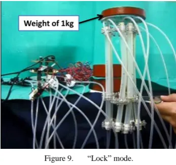
Figure 9. “Lock” mode.
Fig. 9 shows the view of experiment to confirm the “lock” mode. In the experiment, the weight with mass of
1 kg was put on the upper stage when the supply pressure of 450kPa is applied as “lock” mode. As a result, we confirmed that the robot can hold the weight properly by “lock” mode even if it works smoothly in “push” and “pull” modes. The generated locking force is more than 50 N.
Fig. 10 shows the transient view of experiment to test the “free” mode. In the experiment, all three cylinders were used as “free” mode after “reset” mode. From Fig. 10, it can be seen that the robot arm can be driven manually. The force required to drive the robot arm is less than 5 N. As a result, we confirmed that the master device with the function of backdrivability could be realized.
Figure 10. ”Free” mode.
IV. CONCLUTIONS
This study aiming at the development of flexible pneumatic cylinder with backdrivability and its application can be summarized as follows:
We proposed and tested the flexible pneumatic cylinder with backdrivability. the operating principle of the cylinder that has five motions such as “push”, “pull”, “lock”, “reset” and “free” modes was also introduced.
As an application, we proposed and tested the robot arm using the three tested cylinders. The control system of the flexible robot arm using an embedded controller and twelve on-off control valves was also tested.
The driving test of the tested robot arm was carried out. As a result, we confirmed that the robot arm can be held surely by “lock” mode even if it works smoothly in “push” and “pull” modes. We also confirmed that the master device with function of backdrivability could be realized.
As a future work, we are going to develop the bilateral master slave control system using the tested master device for the wrist rehabilitation.
ACKNOWLEDGMENT
Finally, we express our thanks that a part of this research was supported by a research-aid fund from the Ministry of Education, Culture, Sports, Science and Technology through a Financial Assistance Program for QOL Innovative Research (2012-) and a Grant-in-Aid for Scientific Research (C) (Subject No. 24560315).
REFERENCES
handbook of Japan 2013. [Online]. Available: http://www.stat.go.jp/english/data/handbook/c0117.htm
[2] M. Ishii, K. Yamamoto, and K. Hyodo, “Stand-alone wearable power assist suit-development and availability,” Journal of Robotics and Mechatronics, vol. 17, no. 5, pp. 575–583, 2005. [3] J. Piquion, A. Nayar, A. Ghazaryan, R. Papann, W. Klimek, and R.
Laroia, “Robot-assisted gynecological surgery in a community setting,” Journal of Robotics and Surgery, vol. 3, no. 2, pp. 61–64, 2009.
[4] T. Noritsugu, M. Takaiwa, and D. Sasaki, “Development of power assist wear using pneumatic rubber artificial muscles,” Journal of Robotics and Mechatronics, vol. 21, no. 5, pp. 607–613, 2009.
[5] H. Kobayashi, T. Shiban, and Y. Ishida, “Realization of all 7 motions for the upper limb by a muscle suit,” Journal of Robotics and Mechatronics, vol. 16, no. 5, pp. 504–512, 2004.
[6] Y. Nagata, ed. Soft-Actuators-Forefront of Development, Tokyo, NTS Ltd., 2004, pp. 291-335.
[7] T. Akagi and S. Dohta, “Development of a rodless type flexible pneumatic cylinder and its application,” JSME Trans., Series C, vol. 73, no. 731, pp. 2108–2114, 2007.
[8] T. Fujikawa, S. Dohta, and T. Akagi, “Development and attitude control of flexible robot arm with simple structure using flexible pneumatic cylinders,” in Proc. 4th Asia International Symposium on Mechatronics, 2010, pp. 136–141.
[9] F. Zhao, S. Dohta, and T. Akagi, “Development and analysis of small-size quasi-servo valve for flexible bending actuator,” JSME Trans., Series C, vol. 76, no. 772, pp. 3665–3671, 2009.
[10] M. Aliff, S. Dohta, T. Akagi, and H. Li, “Development of a simple-structured pneumatic robot arm and its control using low-cost embedded controller,” Journal of Procedia Engineering, vol. 41, pp. 134–142, 2012.
Takafumi Morimoto is a graduate student (Master course) at Okayama
University of Science. He received the Bachelor of Engineering from Okayama University of Science in 2014.
Mohd Aliff is a graduate student (Doctor course) at Okayama
University of Science. He received the Bachelor of Engineering from Okayama University in 2010 and he received the Master of Engineering from Okayama University of Science in 2012.
Tetsuya Akagi is currently a Professor of Intelligent Mechanical
Engineering Department in Okayama University of Science, Japan. He has been working in this university since 2005. He received the Master of Engineering and the Doctor of Engineering from Okayama University of Science in 1995 and 1998, respectively. From 1998 to 2005, he was a faculty of Tsuyama National College of Technology, Japan. His research interests include mechatronics and robotics; especially wearable control systems using microcomputers and wearable control devices such as flexible pneumatic actuator, soft sensor and wearable control valve.
Shujiro Dohta is currently a Professor of Intelligent Mechanical