A Case Study of a Pull Rod Failure in ATOX Raw Grinding
Mill
Biju
Karakkunnummal
*R&D Product Development, Flsmidth Private Limited, 34 Egatoor Kelambakkam, India
* Corresponding author. email: [email protected] Manuscript submitted January 22, 2015; accepted June 18, 2015.
Abstract: Pull rods made of alloy steel are used to exert grinding pressure on the rollers in the raw grinding
mill. The grinding forces are transmitted vertically by three pull rods placed at 1200 apart directly into the hydraulic cylinder. This paper describes the metallurgical investigation that was carried on a failed pull rod to understand the cause of failure. The fracture surface of the failed pull rod with multiple ratchet marks indicated that the crack was initiated at multiple regions. Higher fatigue zone (55%) with low overload region (45%) indicated that the load was light, but there were high stress concentration zones on the pull rod. Macro-etch test and microstructure analysis indicated the presence of a non-homogeneous structure in the forged pull rod. The presence of unbroken dendrites, blowholes, and exogenous type inclusions was evident from the investigation. To confirm and identify the type of foreign particle, scanning electron microscope with energy dispersive X-ray (SEM-EDX) analysis was performed and concluded the presence of exogenous type of inclusions. The investigation clearly revealed that the crack was initiated due to the presence of non-homogeneous structure in the pull rod and propagated by fatigue mode.
Key words: Fatigue failure, fractography, exogenous inclusions, unbroken dendrites, raw grinding mill.
1.
Introduction
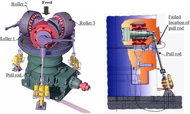
ATOX raw grinding mill [1] uses the pressure and the shear generated between the roller and the rotating table to crush and grind the raw material. Feed material is directed onto the grinding table by feed chute. The rotation of the grinding table accelerates the material towards the grinding tracks and passes it into the rollers. Partially ground material passes over the dam ring encircling the grinding table and into the hot gas stream coming from the nozzle ring. The roller assembly is kept centered on the grinding table and prevented from rotating by three torque rods attached to the mill housing. The grinding pressure was exerted hydraulically through three pull rods attached to the outer ends of each roller shaft. This unique ATOX roller suspension ensures that the grinding forces are transmitted vertically by the pull rods directly into the hydraulic cylinder and foundation and horizontally by the torque rods into the mill housing.
spare pull rods were also failed during the operation. The analysis [2] was done on the first failed pull rod. The failed pull rod was located at the feed end of grinding mill. During the shutdown operation, roller replacement on roller 1 was carried out. Customer has informed that other two rollers were not disturbed during the replacement of roller 1. The following activities were carried out on roller 3 for the past two years where the failed pull rod was placed.
Fig. 1. Pull rod location in ATOX raw mill
1. July 2013 : Joint Head with bearing was replaced
2. July 2013 : Hydraulic cylinder bottom eye bearing was replaced 3. Jan 2014 : Rubber damper rubber was replaced
4. July 2014 : Original pull rod failed 5. Aug 2014 : Spare (1) pull rod installed 6. Sept 2014 : Spare (1) pull rod failed 7. Oct 2014 : 2nd spare pull rod installed 8. Oct 2014 : 2nd spare pull rod failed
2.
Testing and Analysis
2.1.
Visual Examination
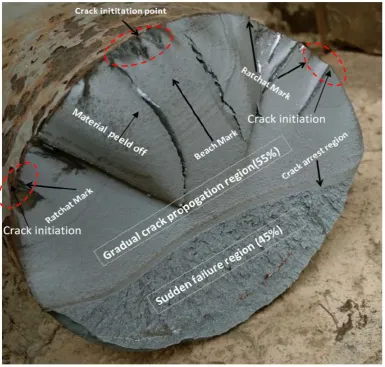
Visual examination was performed using low magnification lens. As received pull rod material was rusted heavily and no material identification mark was seen on the sample. Examination of the fracture surface is shown in Fig. 3, revealed characteristics such as beach mark associated with fatigue. Multiple cracks were visible on the fracture surface. At some location, material was peeled off from the fracture surface. Several ratchet marks were visible on the fracture surface, which indicates multiple crack initiation region. The fracture surface shows a clear indication of fatigue failure. The edges of crack resembles multi branching tree like appearance.
Fig. 3. Fracture surface of failed pull rod.
2.1.1.
Fractography
Fig. 4. Flaky appearance of material removal from the pull rod.
Fig. 5. Flaky appearance of material removal from the pull rod.
From the Fractography [4] several ratchet marks were noticed which indicate that the cracks started from several locations.
The following points [5], [6] were drawn from the visual examination.
1. Multiple ratchets marking indicates that crack was initiated from several location of pull rod. This might have resulted due to high stress or high stress concentration.
2. The measured overload zone was 45% that is less than the fatigue zone (55%). 3. The presence of ratchet marks indicates a multiple origins of crack.
4. Several ratchet marks and low overload region indicates that the load was light, but there were high stress concentration.
5. Morphology of fracture surface indicates the failure was due to one side-bending load from the crack initiation region.
6. The side of ratchet mark was perpendicular to the fracture surface (refer figure 4), which indicates that the plane bending or tension caused the failure.
7. The sharp corners are visible on the fracture surface, which indicates the presence of stress concentration at that area.
8. Stress concentration arises due to several reasons such as poor radius of curvature, weld repair on the pull rod, slag inclusions, corrosion etc.
9. The material removal was in a flaky manner (refer figure 5). At some location, no cracks were present at the surface, but at the core region.
10. It was informed that no other related failure of bolt and nuts took place along with the pull rod.
11. The fractography [5] shows small overload region and large fatigue region with multiple ratchet
2.1.2. Test Sample Locations
Location of Sample taken for the different analysis are given in Fig. 6
Fig. 6. Location of test sample taken for analysis
2.2.
Chemical Analysis
The chemical composition of pull rod was determined by optical emission spectrometry (OES) with the result presented in Table 1.Chemical analysis at various location revealed that the pull rod met the chemical composition as per EN 10083-3.This test was conducted to confirm the specified material was supplied by the manufacturer.
Table 1. Chemical Analysis of Pull Rod Material.
%Elements %C %Si %Mn %P %S %Al %Cr %Mo %Ni %Cu
Specification 0.26-0.34 0.40 0.5-0.80 0.025 0.035 - 1.8-2.50 0.3-0.50 1.8-2.20 -
Actual 0.288 0.232 0.431 0.0029 0.005 0.0031 1.995 0.308 1.821 0.177
2.3.
Tensile Test
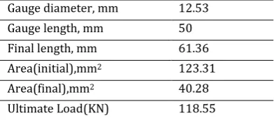
Tensile test was carried out on the failed sample as per ASTM 370-2011. Details of test parameters are given in Table 2. The tensile strength of the failed pull rod was less than the specification limit. The details of test results are presented in Table 3 and its explanation are presented in the discussion section.
Table 2. Tensile Test Parameters
Gauge diameter, mm 12.53
Gauge length, mm 50
Final length, mm 61.36
Area(initial),mm2 123.31
Area(final),mm2 40.28
Fig. 7. Load versus elongation curve of failed tensile sample.
Fig. 8. Fracture surface of tensile specimen
Table 3. Tensile Properties of Failed Pull Rod Material
Ultimate tensile strength(MPa) Yield strength (MPa) %Elongation % Reduction
Specification 1000-1200 800 11 50
Actual 961.39 832 22.5 67.5
2.4.
Macro Etch Test
Fig. 9. Macro etched sample (a-c); Stereographic macro examination (d)
2.5.
Impact Test
Charpy V notch Impact test was carried out at room temperature as per ASTM E23-2007 to understand the toughness characteristics of pull rod. Results obtained from the impact test are given in the Table 4.
Table 4. Impact Test Results of Failed Sample
Specification Reading 1 Reading 2 Reading 3 Average
Absorbed Energy (Jouls) 45 136 126 126 129.33
The impact test result conforms as per the specification. Fracture surface of broken 'V' notch specimen was examined. Fracture surface appearance was 100% fibrous in nature.
2.6.
Hardness Measurements
Hardness mapping was carried out from surface to core (around 72 points) as per ASTM E 10-2010. The test results are shown in Fig. 10. Variations in hardness were observed from surface to core as shown in Fig. 10.
Fig. 10. Hardness mapping (surface to core) in the shaft
2.7.
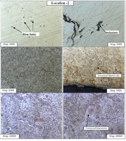
Material Characterizations
Figure 12(a). Micro examination at location 3.
Fig. 12(b). Micro examination at location 4.
2.8.
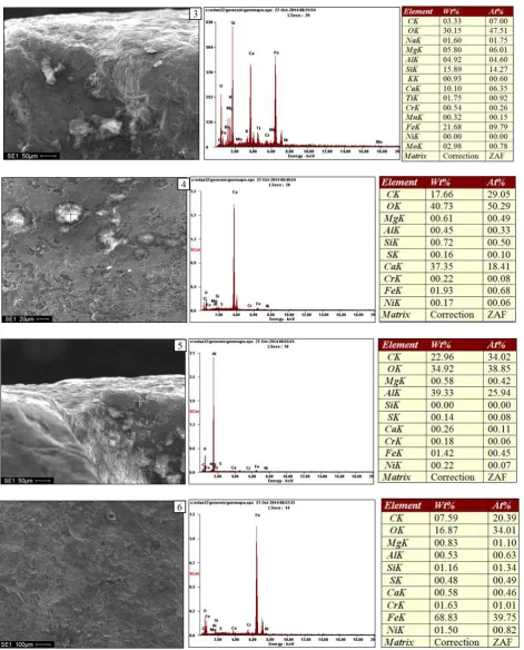
SEM-EDX Analysis
The relative quantities of elements of failed sample were determined by Energy dispersed X-ray elemental spectrometer. The scanning electron micrographs taken at different location of the crack region are presented in Fig. 13(1 to 6).
The fracture surface of the pull rod was cut at various locations to study the Fractography .The fracture surface was cleaned with acetone in order to remove the foreign deposits. The scanning electron micrograph is shown in Fig. 13-6, clearly indicates that the fracture surface is smooth and crack propagated by transgranular mode [7]. There is no detachment of grain observed in the micrograph. The crack propagated across the grain boundary and failed by fatigue mode. However at the crack initiation point the presence of exogenous inclusion was noticed with the help energy dispersive X-ray analysis.
Scanning electron micrograph taken at various locations shows predominantly the presence of exogenous type of inclusions which would be the cause of failure of pull rod.
1
Fig. 13. SEM-EDX analysis at the crack region
3.
Results
3.1. Visual Inspection
The fracture surface showed beach mark associated with fatigue. Several ratchet marks were also visible on the fracture surface, which is an indication of multiple crack initiation. Sharp corners on the fracture
3
6 5 4
surface also indicated the presence of stress concentration on the pull rod material. The surface area of final fraction was approximately 45% of the total fracture surface suggesting that the pull rod was over stressed. Small overload region and large fatigue region with multiple ratchet marks indicates that the load was light, but there were high stress concentration on the crack initiation region. It was informed that there was no related failure of bolt, nuts along with the pull rod failure. Any overloading or high bending stress would have caused the failure of bolts, which was connected with the pull rod. From this analysis, we conclude that the bad quality of the pull rod material caused the premature failure.
3.2. Chemical Analysis
Chemical analysis performed on the body of the pull rod confirmed it to be EN 10083-2.
3.3.
Tensile Test
Tensile test was carried out at room temperature in longitudinal direction to understand the tensile property of the pull rod. The results are summarized in Table 3. The test results showed that tensile properties were slightly lower than the usual test results. The tensile strength was lower than the specified value and yield strength was only marginally above the specified value. The tensile specimen showed cup and cone fracture with sufficient necking, which shows the ductile behavior of material. The ductility of the material was good, but the fatigue property of the material would have reduced due to the poor tensile strength. The reduction in tensile property of material could be due the presence of non-homogeneous structure, which is presented in the subsequent discussion.
3.4.
Macro examination:
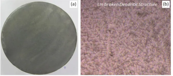
Macro examination was carried out using 1:1 hot solution of hydrochloric acid and water for 30 minutes. Severe blowholes and pinholes were noticed in the macro-etched specimen. There was an unbroken coarse dendritic structure visible, which is not acceptable for a forged product. We also noticed a segregation pattern at certain regions of macro-etched specimen. The macro-etched specimen revealed a non-homogenized structure.
3.5.
Impact Test
The required impact energy for pull rod material was minimum 40 Jouls and the result was as per the specification limit.
3.6.
Hardness Mapping
Vicker hardness mapping was carried out at an interval of 2 mm on the cut section of pull rod from surface to core. The results are summarized in figure 10. A large variation of hardness was observed at several locations. The variation in hardness would be due to the segregated pattern in the unbroken dendritic structure and the presence of non-homogenize microstructure structure and other anomalies such as blowholes, inclusion etc.
3.7.
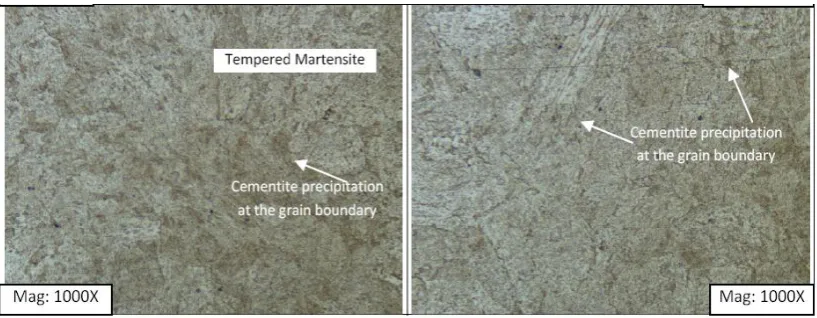
Microstructure
Characterization
3.8. SEM-EDX Analysis
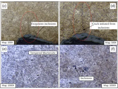
The relative quantities of elements were determined by EDX analysis and results are summarized in Fig. 13. SEM-EDX analysis at the edges of crack revealed the presence of oxides of Alumina, Calcium and Silicate. These exogenous inclusions [8] lead to increase in stress concentration and cracks had initiated from this point and propagated through the unbroken inter dendritic region. The crack initiation depends on the severity of inclusion present in the structure (Fig. 14).
Fig. 14. Crack initiation and propagation
4.
Conclusions
On the basis of the metallurgical investigation carried out on the failed pull rod, the following conclusions were made.
1. Small overload region and large fatigue region associated with multiple ratchet marks on the fracture surface indicates that the load was light, but there were high stress concentration in the crack initiated region.
2. Chemical Analysis confirmed that the pull rod material was as per EN 10083-2
3. Unbroken dendritic structure resulted in micro segregation in inter-dendritic region, and other anomalies such as blowholes and inclusions accelerated the failure.
4. In the SEM-EDX analysis, presence of exogenous type inclusions such as Al2O3, MgO, SiO2 was noticed.The exogenous type inclusions created a stress concentration and initiated cracks during the operation.
5. The crack was caused by low cycle fatigue, which was initiated due to the presence of exogenous type inclusions in the pull rod. The de-cohesion of inclusions leads to micro cracks on the surface and propagated along the inter dendritic region by fatigue mode.
Acknowledgement
References
[1] FLSmidth ATOXTM raw mill manual. Retrieved January 01, 2015, from http://www.flsmidth.com/~/media/Brochures/Brochures%20for%20raw%20grinding%20and%20s ilos/ATOX_Raw_Mill.pdf
[2] Ramachandran, V., Raghuram, A. C., Krishnan, R. V., Bhaumik, & S. K. (2005). Failure Analysis of Engineering Structures Methodology and Case Histories, 19-23.
[3] Becker, W. T. University of Tennessee, Emeritus; S. Lampman, ASM International. Retrieved January 1,
2015, from
http://jpkc.fudan.edu.cn/picture/article/348/1b/ee/6dce0ae740cf8673b53e4e96abb8/6ad0c8ee-53c3-4790-a931-211df202df69.pdf
[4] Michael J. M., Arthur H. G., & John M. T. (2007). Fracture surface analysis. Journal of Advanced Material & Processes, 21-23.
[5] Neville, W., & Sachs, P. E. (2005). Understanding the surface features of fatigue fractures. How they describe the failure cause and the failure history. Journal of Failure Analysis and Prevention, 5(2), 11-15. [6] Neville S., President of Sachs. (1999). Root Cause Failure Analysis-Interpretation of Fatigue Failures,
Reliability Magazine, from http://www.reliability.com/industry/articles/article29.pdf
[7] Kuna, M. (2013). Finite Elements in Fracture Mechanics, Solid Mechanics and Its Applications 201, Springer Science +business Media Dordrecht, 13-20.
[8] Canale, L. C. F., Mesquita, R. A., Totten G. E. (2008). Failure Analysis of Heat Treated Steel Components -ASM International, 229.