Name : H.Kamanehazari
Designation :M.s student, Organization : Department of Structural Engineering, , Islamic Azad University-Shabestar Email ID : [email protected]
Name : F.Tadbiri
Designation :M.s student, Organization : Department of Structural Engineering, , Islamic Azad University-Shabestar, Email ID : [email protected]
Abstract — Reinforced concrete structures consists of two main components and the behavior of these structures influenced by gender and material properties, in order to investigate the behavior of concrete reinforced beam that most important flexural element in reinforced concrete structures, we chosen High Strength Concrete (HSC) for concrete and GFRP and steel bars for reinforcement. For compare the new beam element(high strength concrete and GFRP bars) ,with general beam (general concrete and steel bars) finite element software ABAQUS used, therefore flexural beam models in this software after simulation and analysis, the results shows that the stress in this elements are reduced.
Keyword — Flexural element
,
High Strength Concrete, GFRP bars,ABAQUS1. I
NTRODUCTIONIn these days ,the concrete structures in building industry are research attention require to investigate in this field. So it needs to be applied according to international standards; for this reason the use of new technology seems essential in building industry, there for developments that have occurred in field of material technology, researchers are using their main priority. Based on this newly materials such as that FRP composite and behavior of them that main topic of this paper. Because of the advantages such as resistance to corrosion, high tensile strength, low weight and insulation against electromagnetic waves can be expressed in these materials. so in the first step in this paper to provide a new method of structure design we treat about concrete material , reinforcement bars of the beam that the one the main elements of structure.
2.
R
ESEARCHM
ODELSBeams are one of the main elements of building structures and usually can be applied in a different rectangular section in reinforced concrete structures. So
in this study the model of the beam is rectangular cross section that identified in table 1.
Table 1. Information of rectangular cross section beam Height(cm) Width (cm) Longitude)cm)
20 15 200
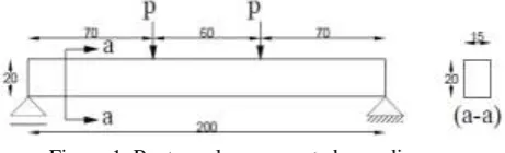
Considering that most of the reinforced concrete structure members are under bending so design and study about under bending concrete sections are primary and most important issues in reinforced concrete section structures.To study the behavior of reinforced concrete structure under bending loads we choices a simple ends beam under a two concentrated load in the thirds of the length figure 1.
Figure 1. Rectangulaer concrete beam diagram
3.
M
ECANICALP
ROPERTIES OFM
ODELS3.1 Concrete
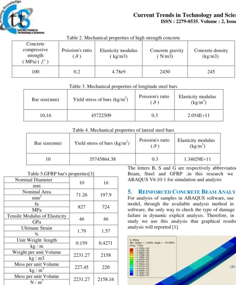
According to this study, we use a high performance concrete beam so the mechanical properties of concrete is show in table (2) .
3.2. Steel bar
The beam that study in this research are reinforced and we use the reinforced concrete beam with steel bars for compare with other simulation models the mechanical of steel bars are shown in table (3, 4).
3.3. GFRP bars
In this research we want to replacing GFRP bars with steel ones,so it is nessecary to know GFRP mechanical properties that this details are in table 5.
Copyright © 2012 CTTS.IN, All right reserved Table 2. Mechanical properties of high strength concrete
Concrete density (kg/m3( Concrete gravity
( N/m3 ) Elasticity modulus
( kg/m3 ) Poission's ratio
)
( Concretecompressive strength
(
c
f
( ) MPa )
245 2450
4.78e9 0.2
100
Table 3. Mechanical properties of longitude steel bars
Elasticity modulus )kg/m3(
Poission's ratio )
( Yield stress of bars (kg/m2)Bar size(mm)
2.054E+11 0.3
45722509 10,16
Table 4. Mechanical properties of lateral steel bars
Elasticity modulus )kg/m3(
Poission's ratio )
( Yield stress of bars (kg/m2)Bar size(mm)
1.34029E+11 0.3
35745864.38 10
Table 5.GFRP bar's properties[3] 16 10
Nominal Diameter mm
197.9 71.26
Nominal Area mm2
724 827
fu MPa
46 46
Tensile Modulus of Elasticity GPa
1.57 1.79
Ultimate Strain %
0.4271 0.159
Unit Weight /length kg / m
2158 2231.27
Weight per unit Volume kg / m3
220 227.45
Mess per unit Volume kg / m3
2158.16 2231.27
Mess per unit Volume N / m3
The authors of the accepted manuscripts will be given a copyright form and the form should accompany your final submission.
4.
D
ETAILS OFR
EAINFORCEDC
ONCRETEB
EAMM
ODEL INF
INITEE
LEMENTS
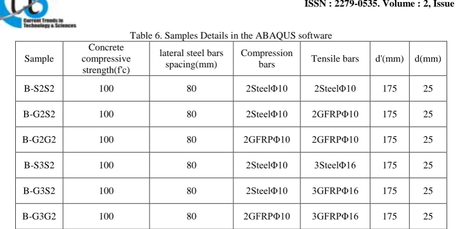
OFTWAREDetails of samples beam that study in finite element software (ABAQUS) are collected and gathered in table 6.
The letters B, S and G are respectively abbreviation of Beam, Steel and GFRP .in this research we use ABAQUS V6.10-1 for simulation and analysis
5.
R
EINFORCEDC
ONCRETEB
EAMA
NALYSISFor analysis of samples in ABAQUS software, use step model, through the available analysis method in this software, the only way to check the type of damage and failure in dynamic explicit analysis. Therefore, in this study we use this analysis that graphical results of analysis will reported [1].
Figure 2. Graphical results of B-G2G2 model
Table 6. Samples Details in the ABAQUS software
d(mm) d'(mm)
Tensile bars Compression
bars lateral steel bars
spacing(mm) Concrete
compressive strength(f'c) Sample
25 175
2SteelΦ10 2SteelΦ10
80 100
B-S2S2
25 175
2GFRPΦ10 2SteelΦ10
80 100
B-G2S2
25 175
2GFRPΦ10 2GFRPΦ10
80 100
B-G2G2
25 175
3SteelΦ16 2SteelΦ10
80 100
B-S3S2
25 175
3GFRPΦ16 2SteelΦ10
80 100
B-G3S2
25 175
3GFRPΦ16 2GFRPΦ10
80 100
B-G3G2
information about results of this model analysis use reference[1].
Figure 3. Graphical results of B-G2S2 model
In above model the tension bars are 2 GFRP bar with size 10 mm and the maximum stress in this model has occur in compression bars.
Figure 4. Graphical results of B-G2S2 model
In above model all of the main bars are GFRP, the purpose of this replacement is review the GFRP compression bars area role in reduce the flexural member
stress.The maximum stress that occur in this model shows that beam reinforcement tolerate minimum stress
and replacing GFRP bars and increase the compression strength of concrete play adhesive role in stress reduce.
Figure 5. Graphical results of B-S3S2 model
Above model is one of the another control model that the all of the beam bars are steel with increase 2 to 3 bars and tension bars size 10 to 16 mm. Meanwhile we study about increasing the percentage of beam reinforced behavior especially in tension area.
Figure 6. Graphical results of B-G3S2 model
Copyright © 2012 CTTS.IN, All right reserved Figure 7. Graphical results of B-G3G2 model
In this model all of the bars are reinforcement with GFRP bars to study the role of compression area bars in improve the tensile behavior of flexuralmembers.
6.
C
ONCLUSIONSTo review the results of the analysis, using outlining column charts for discussion and conclusion
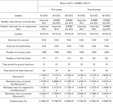
Table 7. Summarize the results of the analysis in ABAQUS software
Beam with f'c=100MPa (20x15)
First group Second group
samples B-S2S2 B-G2S2 B-G2G2 B-S3S2 B-G3S2 B-G3G2
Number, kind and size of tensile bars 2steel bar Φ10
2GFRP bar Φ10
2GFRP bar Φ10
3steel bar Φ16
3GFRP bar Φ16
3GFRP bar Φ16 Number, kind and size of compression
bars
2steel bar Φ10
2steel bar Φ10
2GFRP bar Φ10
2steel bar Φ10
2steel bar Φ10
2GFRP bar Φ10 Load(n) 38710.26 38710.26 38710.26 38710.26 38710.26 38710.26
Seed size for concrete 0.04 0.04 0.04 0.04 0.04 0.04
Seed size for bar&stirrup 0.06 0.06 0.06 0.06 0.06 0.06
Number of concrete mesh 1000 1000 1000 1000 1000 1000
Number of steel bar mesh 372 372 372 381 381 381
Time period for gravity load (sec) 25 25 25 25 25 25
Time period for main load (sec) 60 50 50 50 50 50
Stress(n/m2) 1.783E+0 6
1.517E+0 6
4.795E+0 5
1.635E+0 6
1.527E+0 6
4.807E+0 5 Maximum stress in tensile
bar.Mises(n/m2)
1.783E+0 6
5.088E+0 5
4.120E+0 5
1.635E+0 6
5.101E+0 5
4.041E+0 5 Maximum stress in compressive
bar.Mises(n/m2)
1.634E+0 6
1.517E+0 6
3.778E+0 5
1.635E+0 6
1.527E+0 6
3.368E+0 5 Maximum stress in concrete
.Mises(n/m2)
4.650E+0 5
4.789E+0 5
4.795E+0 5
4.684E+0 5
4.700E+0 5
Chart 1. Compares the results of the first group of beams
according to chart (1) and by taking control model (B-S2S2) it shows that after each replace the steel with GFRP bars stage in same condition of loading (ultimate capacity 38710.36 N) stress value is reduce and in the best condition that all of steel bars are replacement , stress value 73% reduced
and according to chart (2) and by taking control model (B-S3S2) it shows that after each replacement the steel with GFRP bars stage in same condition of loading , stress value 70.67% reduced.
Chart 2. Compares the results of the second group of beams
1. In rectangular sections by replacing the tensile bars with GFRP 10 mm bar shows that the average tension 14.85% reduce and if the bars in tensile area increase to 3 bars, the stress 4% reduced. the purpose of study models that in tensile area have 3 longitude bar is ductility that the results of analysis shows 10% increase in ductility. 2. In rectangular sections by replacing all of the steel bars with 10 mm GFRP bars the average stress 75% decrease, by increasing diameter of GFRP bars in tensile area from 10 to 16 m, stress 73.5% decrease and by increasing the number of tensile areas bar from 2 to 3, the average stress 72.67% decrease.
3. beside the all advantage of FRP bars in improving stress behavior of bending concrete reinforced structure , it make s the weight of structures loses.
4. with improving the stress behavior and loses dead load of structure by using GFRP rebars, In future new development in construction industry particularly the tall structures.
5. as the GFRP plomer bars are considered best type of
special structures such as that hospital and power transmission towers and other strategic structures we can utilize these new materials.
R
EFERENCE[1] H.Kamanehazari, ''FRP reinforced concrete structure elements behavoir'', Master theises, Islamic Azad University-Shabestar, Iran,2012 [2] D.Mostofinejad,''Reinforced Concrete
Structures'', Arkan danesh,first edition,2007 [3] Aslan series 100 Fiber Reinforced Polymer GFRP
bar
[4]
ABAQUS, Users Manual, 2010, Version 6.10.1.
A
UTHOR’
SP
ROFILEHamed Kamanehazari received his B.S in civil in civil engineering at Shabestar university, Iran in 2009 and his M.s in the civil engineering (majoring structural engineering) in the same university at 2012.Hamed kamaneazari research interested are structure elements analysis.