In-Motion Wagon Weighing System
1
Mr. Hidam Gosanta Singh final MCA,
2MsN.Zahira Jahan, MCA.,M.Phil., Associate Professor/MCA Department of MCA, Nandha Engineering College (Autonomous), Erode –52.
---
************************
---Abstract:
Rail transport is a very important part of the modern economy, one of the components determining its dynamic development. It is therefore important to conduct research and taking action aimed at the development and refinement of this branch of industry. Such actions directly translate into an increase in its effectiveness, safety, reduction of burden on the environment and society. Weighing is crucial to cost-control and safety in virtually every aspect of business operation from monitoring product deliveries to avoiding overloading penalties. Often located in remote or harsh conditions, weighing systems need to be in place with minimal disruption to normal traffic. Freight may need to be weighed at high speed as many customers operate a huge variety of locomotives and rolling stock.
Keywords — Loadcell, Indicator, and FOSI(Freight Operations information System) .
---
************************
---I. INTRODUCTION
Railway transport is very important for the development of the modern economy this is why many research works concerning with problems occurring in this way of transport and its development are being carried out all the time. The goal of those works are usually to develop the infrastructure that is used for transport of goods and people, make it more cost-effective, safe and less burdensome for the environment Very important are problems of freight wagons dynamics during exploitation in variety driving conditions . In all of those works the problem of modelling of real object has a strong influence on obtained results and has to be solved using precise methods. This is why computer-aided methods, include Finite Element Method, are used very often . On the other hand, experimental analysis and tests are also very important in order to verify results of calculations and simulations
II. EXPERIMENTAL DETAILS
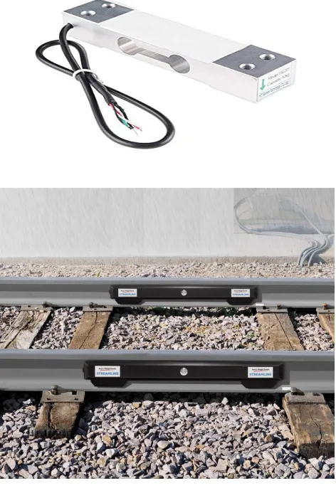
A. Load cell
A load cell is a transducer that is used to create an electrical signal whose magnitude is directly proportional to the force being measured. The various load cell types include hydraulic, pneumatic, and strain gauge. One or more load cells can be used for sensing a single load. If the force can be concentrated to a single point (small scale sensing, ropes, tensile loads, point loads), a single cell can be used. For long beams, two cells at the end are used. Vertical cylinders can be measured at three points, rectangular objects usually require four sensors. More sensors are used for large containers or platforms, or very high loads. If the loads are guaranteed to be symmetrical, some of the load cells can be substituted with pivots. This saves the cost of the load cell but can significantly decrease accuracy. Load cells can be connected in parallel; in that case, all the corresponding signals are connected together (Ex+ to Ex+, S+ to S+, ...), and the resulting signal is the average of the signals from all the sensing elements. This is often used in e.g. personal scales, or other multipoint weight
sensors. The most common color assignment is red for Ex+, black for Ex−, green for S+, and white for S−. Less common assignments are red for Ex+, white for Ex−, green for S+, and blue for S−, or red for Ex+, blue for Ex−, green for S+, and yellow for S−.Other values are also possible, e.g. red for Ex+, green for Ex−, yellow for S+ and blue for S
Fig 1. Load cell
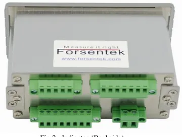
B. Indicator
The Intuitive2-L load cell digital indicator utilises a modular construction technique enabling it to be configured with the exact functionality required for your application, ensuring that you only pay for the features that you need. The load cell readout is provided by a 6-digit LED display coupled with an ultra-high resolution 20-bit A/D
excitation source to provide superb resolution and stability in any application. As its name implies, the Intuitive2-L load cell digital indicator is simple to install and calibrate using just the 4 front panel buttons and on-display prompts – there are no tricky menus to navigate. Options available include voltage or current analogue outputs, 2 or 4 alarm relays and a serial data output in one of several formats including RS232, RS485 and Ethernet, making this a truly flexible load cell digital indicator. Should you require portability, a compact desktop enclosure, the PCC, is also available to suit the Intuitive2 load cell digital indicator, or any other model from the Intuitive2 range. The Intuitive2-L is an ideal replacement for the now obsolete Druck DPI 280 and DPI 281 indicators as it can be configured to provide all of the same functionality.
1. 6-Digit LED Display (±199999)
2. Input: up to 4mV/V as standard (up to 300mV/V on request)
3. Environmental Protection: IP65 (when installed)
4. 10Vdc Load Cell Excitation @ 120mA max. Powers up to 4x 350Ω Load Cells
5. Options: Alarm Relays, Analogue & Digital Outputs
6. Customisation Of Software 7. Portable Desktop Enclosure
Fig 2. Indicator (Backside)
C. indicator wire for system
The full-bridge cells come typically in
four-wire configuration. The wires to the top and bottom
end of the bridge are the excitation (often labelled E+ and E−, or Ex+ and Ex−), the wires to its sides are the signal (labelled S+ and S−). Ideally, the voltage difference between S+ and S− is zero under zero load, and grows proportionally to the load cell's mechanical load. Sometimes a six-wire configuration is used. The two additional wires are "sense" (Sen+ and Sen−), and are connected to the bridge with the Ex+ and Ex- wires, in a fashion similar to four-terminal sensing. With these additional signals, the controller can compensate for the change in wire resistance due to e.g. temperature fluctuations.
The individual resistors on the bridge usually have resistance of 350 Ω. Sometimes other values (typically 120 Ω, 1,000 Ω) can be encountered.
The bridge is typically electrically insulated from the substrate. The sensing elements are in close proximity and in good mutual thermal contact, to avoid differential signals caused by temperature differences.
Fig 3. Wire of Indicator
D. FOIS( Freight Operations information System)
Indian Railways (IR) carries nearly 1012 Million Tonnes of Freight in a year as reported from FOIS System in Year 2013-14. Freight trains bring two thirds of the Indian Railway revenues and are referred to as the bread earners for the Railways. The major commodities carried by Indian Railways are Coal, Iron Ore, Food grains, Iron & Steel, Cement, Petroleum products, Fertilizer and Containerized Traffic. There are specialized wagons to handle the Transportation Needs of the different types of commodities. Unlike passenger carrying trains, Freight trains do not run to a fixed schedule thus making Freight Operations a highly Information Intensive activity. Based on this information managers make Allocation Decisions continually to dynamically Optimize Utilization of resources like wagons, locomotives, crew and paths on the network. Real time information allows good decision making and thus ensures high levels of mobility within the system. This realisation has led to the development of Freight Operations Information System (FOIS).
Features
•Extension of the current business practice of bulk movement in train load formation to piecemeal traffic to increase the market share by clubbing and moving together similar type of stock of "Hub & Spoke" arrangement.
•Global tracking of consignments in real time whether in rakes or in individual wagons. The insight and pipeline of consignments would be seamlessly available for timely planning and just in time inventory management.
•FOIS comprises two major subsystems :
•Rake Management System (RMS) for handling the operational aspects of IR.
•Terminal Management System (TMS) for handling the commercial aspects of IR.
Technology
FOIS has been implemented with state-of-the-art technologies, be it Software Technologies, Hardware Technologies, Communication Networks or Management of the entire System.
FOIS is integrated with other operations modules of CRIS using Enterprise Application Integration software and with banks and customer legacy system through SOA using web services. Oracle grid including Oracle Weblogic, Oracle Tuxedo and Oracle DB are used for the same.
• FOIS system has evolved from a traditional Client/Server (Two tier architecture) to three tier architecture.
• High Availability HP Itanium Servers with Oracle 10g Database
• Oracle Tuxedo (Earlier BEA Tuxedo) System and Weblogic Server
• J2EE platform for implementation of reporting, integrations, SOA etc.
• Microsoft Visual Basic 6.0 (EE), Pro *C
• Dedicated OFC cable networks integrated with VSAT to cover-up the widespread connectivity across the nation.
III. Objective
The main objective of this product is to manage the goods weight carried in wagons through rail. Weighing is crucial to cost-control and safety in virtually every aspect of business operation from monitoring product deliveries to avoiding overloading penalties.
Often located in remote or harsh conditions, weighing systems need to be in place with minimal disruption to normal traffic. Freight may need to be weighed at high speed as many customers operate a huge variety of locomotives and rolling stock.
Sometime the wagon carries huge amount weights above the provided carrying capacity. So with this project help we try to limit the weight allowed to carry per wagon or Permission able carrying capacity per wagon. And the Permission able carrying capacity may various according to the source and destination for the transport and the track on which its expected to travel. This limitation on wait will help in the management of the accuracy and the timing to complete the task of delivering
IV. Scope of Work
complete rack of the wagon. In this we will try to share equal weight for the goods. As for all the wagons they have their own weight without any goods so we try to provide zero weight for the empty wagons and the weight will be calculated after zero. In a rack of wagon the engine and the guard at the ends weight are exempted from calculation of the weight.
And the average weight for the complete wagons are calculated without the engine and the guards.
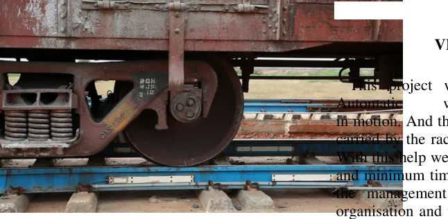
V. EXPERIMENTED RESULTS
Fig 4. Placing of loadcell
The similar project is already placed to serve railways sectors. In this the loadcell calculate the weight of the wagon on the base of the axel available with the single wagon. The total axel will be calculated on average except for the engine and the guard . The calculated details will be shown on the indictor and would be forwarded to the system app so that the info might be stored for the future use. The details might get change while transferring data so we need to provide more advance security system so that it might not be accessible to authorized personnel only.
Fig 5. A Prototype Model
VI.CONCLUSION
This project work is the implementation of Automatic weight measurement of the wagon in motion. And the total weight of the goods that is carried by the rack will be notified to its observer. With this help we will improve the accuracy, safety and minimum time for the transport. It will help in the management of the traffic in the railway organisation and transport with minimum timeline. This will help to minimize the issue or accidents or derailing of the wagon..
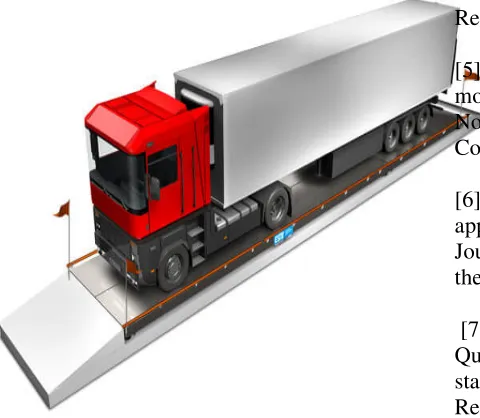
VII.FUTUREENHANCEMENTS
This project should satisfy some features. Features to be tested as follows:
• The details might various will transferring the details so needed to enhance more authenticated
encryption and decryption code for the details.
• Connecting with mobile apps so that the weight could be monitor from distance even if the observer is busy
Fig 6: Future enhancements
The measurement of the weight could be used for the road transport at the point of the toll tax so that exact tax could be collected from the locomotive which passes by, so the responsible personnel could carry limited amount of weight
REFERENCES
[1]Ali, N., Trogdon, J. and Bergan, A. (1994). Evaluation of piezoelectric weigh-in-motion system. Canadian Journal of Civil Engineering, 21, 156-160.
[2] American Society for Testing and Materials (1994). Standard specifications for highway weigh-in-motion (WIM) systems with user requirements and test method. ASTM Designation E 1318-94.
[3]Barnett, J. and Benekohal, R. (1999). Accident reduction effects of using weigh-inmotion and
around truck weigh stations. Transportation Research Record, 1655, 233-240.
[4]Benekohal, R., El-Zohairy, Y., Forrler, E., and Aycin, M. (1999). Truck delay and traffic conflicts around weigh stations. Transportation Research Record, 1653, 52-60.
[5]Bushman, R. and Pratt, A. (1998). Weigh in motion technology – economics and performance. North American Travel Monitoring Exhibition and Conference, Charlotte,
[6]NC. Coffinbargar, W. (1990). Design criteria for application of low-speed weigh-in-motion. ITE Journal, 17-20. Drew D. R. (1968). Traffic flow theory and control. McGraw Hill, 68-13626.
[7]Han, C., Boyd, W., and Marti, M. (1995). Quality control of weigh-in-motion systems using statistical process control. Transportation Research Record, 1501, 72-79.
[8] Hanscom, F. and Goelzer, M. (1998). Truck weight enforcement measures of effectiveness. Transportation Research Record, 1643, 152-160.