Research Journal
Volume 10, No. 32, Dec. 2016, pages 1–8
DOI: 10.12913/22998624/65114 Research Article
ANALYSIS OF PRINTING PARAMETERS FOR PRODUCTION OF
COMPONENTS WITH EASY3DMAKER PRINTER
Alexander Rengevič1, Mikuláš Fúra1, Nadežda Čuboňová1
1 Faculty of Mechanical Engineering, University of Žilina, Univerzitna 1, 010 26, Žilina, Slovakia, e-mail:
[email protected], [email protected], [email protected]
ABSTRACT
The presented article deals with analyses and testing appropriate parameters for the production of components manufactured with rapid prototyping technology –
Easy-3DMaker printer. The quality of the printed component with a specific shape is ana -lyzed. The analyzed materials are ABS Printplus and PLA Printplus. These materials
are printed at different temperatures and speeds. combinations of different settings were tested in order to find the best conditions for printing with different nozzles. The quality of individual printed samples is assessed visually and by touch. The efficiency in terms of print time under various conditions was also analyzed. The main benefit of testing is the establishment of appropriate conditions for printing components on
a Easy3DMaker printer. The article does not focus on mechanical properties of the examined samples.
Keywords: 3D printer, printing parameters, ABS, PLA.
INTRODUCTION
At present rapid prototyping methods are widely used. The application of this method minimizes production costs, improve quality and increase productivity [3, 5]. The speed of produc-tion, price, quality and precision are most impor-tant parameters in the production of prototype
[8]. All these requirements can be achieved with different methods of prototype production. Fre -quently used methods are e.g. Stereolithography (SL) and Selective Laser Sintering (SLS) that use powerful lasers and are installed outside
engi-neering offices [4]. Another alternative technol
-ogy is Fused Deposition Modeling (FDM). This
without-laser method allows creating a physical
model using molten plastic filaments applied in layers on build platform with foam base. Working
materials are most likely non-toxic thermoplasts or waxes. These are in the extrusion head heat-ed up to a temperature slightly higher than their melting point. Then they pass through an
extru-sion nozzle with defined bore diameter to achieve
desired thickness of extruded material. The im-pact of high local temperatures in the contact
area a strong link between molten filament and component’s surface is created. The first layer of filament is fastened on the built platform with a help of thin film of glue, adhesive tape or similar
material with high adhesion. Typical layer thick-ness is within the range of 0.1 mm to 0.25 mm. This type of printing requires creating material supports. There are several ways to create
mate-rial supports. The first way is that they are printed
from same material as the rest of the component
but with different conditions. The second way is that they are printed form different material us -ing a second nozzle. The advantage of the sec-ond method is that none of the materials is mixed
with each other and can be easily separated af -ter printing (e.g. means an aqueous solution or
ultrasound). FDM technology is an interesting compromise between production precision, speed and durability of model. A big advantage of FDM Received: 2016.08.30
Accepted: 2016.10.18
technology is a possibility of deployment compo
-nents in normal office environment. Easy3DMak
-er print-er used in our analysis is also based on this technology [7]. The principle of FDM technology is shown on Figure 1.
ANALYSIS OF APPLIED MATERIALS FOR
3D PRINTING
Currently, plastics are most widely used ma-terials for 3D printing. They are often used in design, architecture, automotive, aircraft tech-nology, and healthcare and electronics industry. The most common plastics are ABS (acrylonitrile
butadiene styrene) and PLA (polylactic acid) [3].
ABS Material
ABS polymers are combinations of mono
-mers acrylonitrile butadiene styrene with signifi
-cantly better chemical resistance and toughness than polystyrene and with retaining sufficient of
rigidity. It is a heterogeneous material. In a con-tinuous phase of styrene acrylonitrile copolymers
are scattered small particles of polybutadiene rub
-ber. ABS polymers have similar morphological
structure as impact polystyrene. They are
charac-terized by low resistance to weathering and aging caused by the influence of light. ABS polymers can be well processed by all common technologi -cal procedures used in thermoplastic injection, rolling, molding, thermoforming and stamping.
Quantitatively, most significant (55%) is injec
-tion at 180°C to 250°C, followed by extrusion on worktops at 150°C to 215°C (35%). The use of other technologies is 10%. ABS can be well glued, welded and finished. In terms of price,
ABS polymers are more expensive than high
im-pact polystyrene or polyolefins, but much cheaper than polyamides and polycarbonates. They have
a low density (1.02 to 1.08 g·cm-3) and therefore
their use is advantageous, compared to the vol-ume unit. The material used for our analysis is
ABS Printplus. It is specifically designed for 3D printing. High precision of filament ensures high
print quality. Low dependence on accurate of
ex-trusion head and durability of printed component
are the major advantages of this material. The material is not recommended for ordinary
print-ing of large objects where the longest dimension exceeds 80mm. Printed component can be easily machined by grinding, drilling and surface can be modify by printing [1].
PLA Material
Polylactic acid belongs to the group of biode
-gradable polyesters. Polylactic acid has a struc -ture of linear polyester. Lactic acid for lactide
preparation may be obtained by glucose fermen
-tation . The raw material is obtained by digestion of starch extractable from normal farming crops, mostly maize, sugar beet and sugarcane. Due to
the PLA interesting properties, such as transpar-ency, low value of ductility, excellent mechanical
strength and biodegrability is application of PLA
very diverse. It is used as a packaging material
in a form of bottles or crucibles. Technologically, it is possible to use any known technology like
injection, extrusion, molding and the like. Poly-lactic acid is, along ABS, the most widely used material for thermoplastic extrusion method of
3D printing, including FDM technology. For the
purposes of 3D printing it is usually supplied in a form of a wire with diameter at 1.75 mm to 3 mm. Compared to ABS, PLA is easier and faster to handle at the same printing conditions. PLA
prod-ucts are considerably less resistant to high temperatures but are less susceptible to distortion
and errors. It does not require the strict
applica-tion of heated worktops. From a material point of view, the products of PLA are less flexible and
have higher gloss [9, 10].
THE EASY3DMAKER PRINTER
Easy3DMaker printer is an easily manageable printer. Due to its properties, it is used by hobby
modelers, designers of small forms and all users which need their 3D designs materialize in
ity and quickly way. The benefits of printer are handling, stability and reliability. For production
of all components of the printer are used alumin-ium alloys and steel [2]. Construction of printer with description of individual parts is shown in
Figure 2. In Table 1 all important parameters of
the printer are lists.
3D printer is able to print with a filament of
of 1.75 mm thickness from ABS or PLA
mate-rial. Depending on bore diameter of a nozzle can be used the thicknesses of layer 0.08 mm, 0.125
mm or 0.25 mm. Extruder head is equipped with stepper motor, which ensures uniformity of
mate-rial dosage. Accurate and reliable positioning of
a movement in the Z axis is achieved using dual
fusing on linear ball bearing. The printer is con
-trolled by G3DMaker software that is supplied
with the 3D printer. It is user friendly and intui-tive software. The user can load and prepare the model for printing directly in the visual
environ-ment. A model can be moved and rotate in x, y and z axis. It is also possible to load several mod -els and change their size. The supported formats for this software are STL and 3DS. The generated
G-code determines the approximate time of print -ing and also consumption of material [2, 6].
METHODOLOGY OF PRINTING
Exploring the best conditions for 3D printing was based on following points:
• used printer Easy3DMaker,
• used materials ABS Printplus and PLA
Printp-lus (suitable for used printer),
• defined shape and dimensions of test sample, • under conditions of printing more testing
sam-ples in less time was selected hexagonal shape
with different sizes of rounded edges and in
-ternal bore to print accuracy,
• used nozzle: 5 mm, 3 mm and 2 mm, in
exper-iments with the sequence of largest to smallest nozzle,
• constant parameters:
– temperature of print table, PLA = 50 °C, – filling form: honeycomb,
– filing density: 50%,
– defaultcooling parameters (for each material),
• use of external cooling fans for shortening the cooling of pad.
TEST SAMPLE FOR 3D PRINT
The defined methodology of work shows that the experimental sample must be simple. Compo
-nents with various shapes and difficult construc
-tion are unsuitable for the purpose of determining
printing conditions [10]. The model of
experimen-tal component is shown in Figure 3. It is a simple component with hexagonal shape with different
rounded edges. The inner hole has a shape of tear.
Different rounded corners are used for detection
of printing precision. Dimensions of experimental
component are 26×24×15 mm. These dimensions were chosen for shortening time and possibility of printing a larger number of test samples. This al -lowed detailed analysis of printing conditions.
PRINT SETTINGS
All settings related to printing are in G3D
-Maker represented with print profiles. The main Table 1. Important parameters of 3D printer
Easy3D-Maker [2]
Printing material ABS, PLA
Dimensions of workspace 200×200×230 [mm] Total modeling space 9200 [cm3]
Resolution of layer 0.08 / 0.125 / 0.25 [mm] Dimensions of 3D printer 400×400×500 [mm]
3D printer weight 16 [kg]
Print speed 80 [mm·s-1]
Power supply/ input power 24V / 180W Maximum temperature 280 °C
Fig. 2. Construction of 3D printer Easy3DMaker: 1 – outer casing, 2 – z-axis servomotor, 3 – material
holder, 4 – power switch, 5 – control electronics, 6 – extrusion head, 7 – build platform, 8 – y-axis
parts of the print profile are common settings,
cooling, speed and advanced settings. In common
settings user define the accuracy, retract, print set
-tings and the skirt. Accuracy defines the height of the first layer and the number of layers to be filled. A retract adjust the speed of pull, length of the pulled material and the number of print table
decreases during retract. Print settings contain
several important parameters which substantially affect the quality of surface and internal structure
of the produced components. This is particularly
solid layers parameter that show a number of hori
-zontal layers on the base and the top of the model, fill pattern that offer different types of the internal
structure. The solid pattern is used to select the shape of the outer layer. Skirt is used to launch
ex-trusion before printing. Cooling allows to set cool -ing fan parameters for proper component
cool-ing. It is possible to start cooling under specified
conditions or cooled constantly during the entire period of the press. Print speed parameters have
substantially affect the quality and accuracy of the
printed parts. In this section are defined speeds of
printing perimeters – vp, small perimeters – vsp,
infill – vi, solid infill – vsi, top solid infill – vtsi,
bridges – vb and external perimeter speed – vep. An important parameter in an advanced setting is extrusion width – ew. This is a theoretical value which indicates the width of the printed material. It is necessary for a proper calculation of the ex-truder path. An advanced setting allows also to set parameters for a support material.
DETERMINE THE PARAMETERS FOR
PLA PRINTPLUS
This section describes production of compo -nents using polymer PLA Printplus material and
nozzles with bore diameter – nd, about a size: nd =
0.5 mm, nd = 0.3 mm and nd = 0.2 mm.
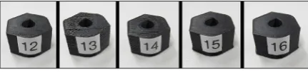
The nozzle 0.5
The first test sample PLA1 was printed with
the random printing parameters.This setting was
based on the user’s manual for the used printer. We started with maximum layer thickness lt =
0.25 mm. The printed component has a high peripheral inequality. The top solid layer and
covering layer insufficiently overlap the inter -nal structure. On the second test sample PLA2 thickness of the extruded layer was reduced to lt = 0.125 mm. It was found that this parameter
has a large impact to print quality. The surface around the perimeter of the component is softer
and the layers have better fitting. Top covering
layer also have less rough surface. The internal
Fig. 3. Model of test sample
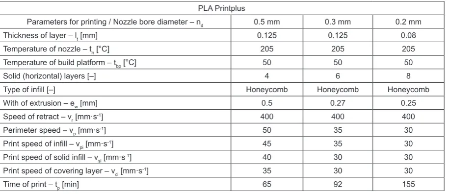
Table 2. Appropriate printing conditions for PLA Printplus
PLA Printplus
Parameters for printing / Nozzle bore diameter – nd 0.5 mm 0.3 mm 0.2 mm
Thickness of layer – lt [mm] 0.125 0.125 0.08
Temperature of nozzle – tn [°C] 205 205 205
Temperature of build platform – tbp [°C] 50 50 50
Solid (horizontal) layers [–] 4 6 8
Type of infill [–] Honeycomb Honeycomb Honeycomb
With of extrusion – ew [mm] 0.5 0.27 0.25
Speed of retract – vr [mm·s-1] 400 400 400
Perimeter speed – vp [mm·s-1] 50 35 30
Print speed of infill – vpi [mm·s-1] 45 35 30
Print speed of solid infill – vsi [mm·s-1] 40 30 30
Print speed of covering layer – vcl [mm·s-1] 35 30 30
structure is printed more accurately, which
con-tributes to higher strength of the finished part. On test samples PLA3 and PLA4 the impact of travel speed was examined. A significant change
of value had no impact on print quality. At the test sample PLA5 the value of a perimeter speed was changed to vp = 40 mm/s. A small variation of this parameter does not cause visible changes
on the surface of part. test sample PLA6 has a similar look, where the speed of covering layer was changed to value vcl = 35 mm/s. The inter -nal structure of the component is not completely
covered because it was set at high speed of the top infill printing. Setting of appropriate temper
-ature for printing was verified at the test sample
PLA7. The temperature was increased from te
= 205°C to te = 215°C. By observation, it was
found that the temperature is too high and leads
to overburning the materialas there were visible
dark material layers on the parts. Test sample
PLA8 was printed with higher number of solid
layers. This slightly lengthens the time of pro-duction. Pictures of the printed samples are
pre-sented in Figure 4.
The nozzle 0.3
The use of nozzle with smaller diameter does not mean that the printed product will
have automatically better quality. Test samples
from PLA9 to PLA16 are produced under the
same conditions as the first 8 test samples. The
surface quality of these samples is very similar to the test samples extruded with nozzle nd = 0.5 mm. For enhanced quality, it is necessary
to amend the previous print settings. A very
im-portant parameter which largely influences the print is the width of extruded material. When
we use a nozzle with diameter nd = 0.3 mm, it
is appropriate to set this parameter at value ew
= 0.27. In case of badly chosen value caused
that component is produced with many errors. In addition to reducing the value of extruded material it was also necessary to reduce the speed of layering. Lower speeds caused thinner
fiber of material was better caught to previous
layer. The surface of a part is softer to touch.
The test sample PLA26 was printed after find
-ing all suitable conditions for nozzle with bore
diameter nd = 0.3 mm. Fibers on covering layer are more linked and cause better covering of the infill. The black spot on the top of compo
-nent is due to inclusion. See Figure 5.
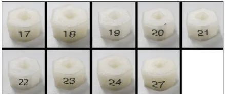
The nozzle 0.2
By using a nozzle with bore dimension
nd = 0.2 mm we are able to make components
with high quality. It was necessary to set thick-ness of extruded layer to the value lt = 0.125 mm or lt = 0.08 mm. The parts printed at the lowest thickness are characterized by top qual -ity of surface and internal structure. Test
sam-ples from PLA 17 to PLA24 were used to find the best conditions for printing with nozzle bore diameter nd = 0.2 mm. Using the most
appropriate conditions for printing form PLA material the test sample PLA27 was printed. A large share to quality of its surface had a low speed of layering. also width of extrusion was changed to value ew = 0.2 mm. The resulting
surface of part is smooth. Compared to other
samples, the test sample PLA27 is the best
printed test sample from PLA.
Fig. 4. The PLA test samples printed with nozzle bore
diameter 0.5 mm
Fig. 5. The PLA test samples printed with nozzle bore
DETERMINE THE PARAMETERS FOR ABS
PRINTPLUS
This section describes how to print test samples from ABS Printplus material with different nozzle bore diameter using a variety of print settings
changes. The section also evaluates the impact of printed parameters to the quality of test samples.
The nozzle 0.5
The test sample ABS1 printed with values
based on user’s manual showed major deficien
-cies. The infill did not have desired shape because
layers are not well connected to each other. The quality of surface was low. The external
perimet-ric layers are shrunk and the base of component
is not completely printed. On Test samples ABS2,
ABS3 and ABS4 values of a retract are gradually changed. The surface of parts is similar to the first sample. The test sample ABS3 is the best made
component form this group of test samples. Ac-cording to the quality of a surface, we can divide thetest sample ABS3 it into two sides. The lower
side is printed better, because the outer periph
-eral layers are adjected to each other. The quality
of the printed edge around the base is also posi -tive. The upper side is printed worse. The external perimetric layers are separated from each other. The covering layer is printed only on half of the surface. By change the thickness of extruded lay-er from value lt = 0.25 mm to lt = 0.125 mm the time doubles the production, whereas the surface
of the component is softer. The component with
serial number ABS7 has a complete base. The pa
-rameter which had influence on print base com -pleteness was the speed of covering layer, which we set to vcl = 35 mm/s. The combination of high
speeds, greater thickness of extruded layers and
low temperature on print table resulted in the poor
quality of the printed component. It is
represent-ed by test sample ABS8. The test samples ABS9,
ABS10 and ABS11 had a speed of covering layer set again to the optimum value vcl = 35 mm/s. The best surface has a test sample ABS9. Sample ABS10 has a slightly concave base, which was caused by low temperature of print table (55°C).
The nozzle 0.3
Change of the width of extruded material to value ew = 0.27 increased spress time from tp =
66 min. to tp = 90 min. On sample ABS12 quality Table 3. Appropriate printing conditions for ABS Printplus
ABS Printplus
Parameters for printing / Nozzle bore diameter – nd 0.5 mm 0.3 mm 0.2 mm
Thickness of layer – lt [mm] 0.125 0.125 0.08
Temperature of nozzle – tn [°C] 225 255 255
Temperature of build platform – tbp [°C] 65 65 80
Solid (horizontal) layers [–] 6 6 8
Type of infill [–] Honeycomb Honeycomb Honeycomb
With of extrusion – ew [mm] 0.5 0.27 0.25
Speed of retract – vr [mm·s-1] 400 400 400
Perimeter speed – vp [mm·s-1] 45 40 35
Print speed of infill – vpi [mm·s-1] 40 35 35
Print speed of solid infill – vsi [mm·s-1] 40 30 30
Print speed of covering layer – vcl [mm·s-1] 35 30 30
Time of print – tp [min] 66 90 151
Fig. 7. The ABS test samples printed with nozzle bore
and soft surface were achieved. The test sample
ABS14 was printed with a width of extruded ma -terial set on the value ew = 0.5 mm. It was found that changing bore diameter of nozzle without
changing the width of extruded material value
is not appropriate. This is because the extrusion head badly recalculates the route. On covering layer small gaps between fibers remained. The
test sample ABS15 has softer surface and high quality of inner structure due to a slower speed.
The nozzle 0.2
Components produced with nozzle bore di -ameter nd = 0.2 mm has the highest quality sur -face. The reason was change of thickness of ex-truded layer to 0.08 mm, change of the width of extruded material to ew = 0.25 mm and reduction
of print speed.
EVALUATION OF RESULTS
A combination of two used materials (PLA, ABS), nozzles with bore diameter nd = 0.5 mm,
nd = 0.3 mm and nd = 0.2 mm and different pa
-rameters 44 test samples were printed. They were intended to evaluate the possibilities of printing with 3D printer Easy3DMaker. For the produc -tion of given components recommenda-tions of appropriate printing conditions for print materials
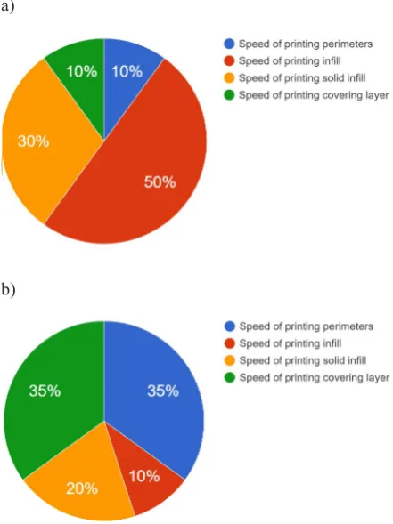
PLA Printplus (see Table 2) and ABS Printplus (see Table 3) were developed. Experiments have shown that the bore diameter of the nozzle has a major impact on the time of printing, but PLA and ABS materials shall not affect the time of printing. For production components with good surface to
set proper values printing speed is required (see
Fig. 10a). From these settings perimeter speed
and speed of covering layer have large impact to
surface quality. For production of quality inter
-nal structure print speed of solid infill is the most important parameter (see Fig. 10b). Suitable con
-ditions for printing with ABS material were
veri-fied to other experimental components with vari -ous shapes. A gear, dice and dodekahedron were
printed (see Fig. 9).
CONCLUSION
This article describes a process of creating methodology to finding best conditions for 3D printing. It also describes printing process and the evaluation of finished components. We found
that the use of appropriate printing conditions, allows us to print components from PLA
Printp-lus in quality comparable to ABS PrintpPrintp-lus. The best conditions for print components with small size provides the nozzle with bore diameter nd =
0.2 mm. Larger nozzles shorten the production time to the detriment of quality. Printing speeds are among the most important print parameters. It was found that with the reduction of the diam-eter of nozzle and thickness of applied layer it is necessary to reduce the value of speeds. This
observation holds true in both used materials. Found suitable conditions will serve as a basis
for further experiments.
Fig. 9. The ABS test sample and experimental
com-ponents printed with nozzle bore diameter 0.2 mm
Fig. 10. Impact parameters: a) surface quality,
b) quality of internal structure
a)
REFERENCES
1. Academy X s.r.o.: ABS. Online: http:// www.3dtlaciaren.eu/abs-printplus/, 2015.
2. AROJA s.r.o.: Užívateľský manuál typ: EASY3D -MAKER. Version 1, 2013.
3. Císar, M.: Diagnosis of equipments. In: Mechani -zation and automation equipment for processing.
Cluj-Napoca: Publishing House Alma Mater, 2015, 209-240.
4. Cotetiu, I., Kuric, I., Novák-Marcinčin, J., Ungure -anu, N.: New trends in mechanical design and
tech-nologies. In: Cluj Napoca, Risoprint, 2005, 224.
5. Kumičáková, D., Jakubčík, M.: Specialised robotic hand designing and object grasping simulation. In: Robotics in theory and practice Book Series: Ap -plied Mechanics and Materials, 2013, 282, pp. 9. 6. Kumičáková, D., Gorski, F., Milecki, A., Grajew
-ski, D.: Utilization of advanced simulation meth
-ods for solving of assembly processes automation
partial tasks. Manufacturing Technology, Vol.
13(4), 2009, pp. 9.
7. Náprstková, N.: CAE 1-Studijní opory. Univerzita J. E. Purkyně v Ústi nad Labem, 2012, pp. 80.
8. Novák-Marcinčin, J., Kuric, I., Mikac, T., Barišič,
B.: Computer support for improvement
engineer-ing and manufacturengineer-ing activities. In: University of Rijeka, 2009, pp. 241.
9. Petruš, J.: Kyselina polymléčná nejen jako biode
-gradabilní polymer. In: www.chempoint.cz, Vysoké učení technické v Brně, Fakulta chemická, 2011.
10. Stančeková, D., Czán, A., Derbas, M.: Investiga
-tion of defects in forging tools by forging tools by
nondestructive detection method. In: Metal 2013
[web source]: 22th International conference on
metallurgy and materials: conference proceedings:
May 15th-17th 2013, Brno, Czech Republic, EU. -
![Fig. 1. Principle of FDM technology [7]](https://thumb-us.123doks.com/thumbv2/123dok_us/8808112.1775676/2.595.73.289.71.242/fig-principle-of-fdm-technology.webp)
![Fig. 2. Construction of 3D printer Easy3DMaker: 1 – outer casing, 2 – z-axis servomotor, 3 – material holder, 4 – power switch, 5 – control electronics,6 – extrusion head, 7 – build platform, 8 – y-axis servomotor [2]](https://thumb-us.123doks.com/thumbv2/123dok_us/8808112.1775676/3.595.71.287.516.708/construction-servomotor-material-control-electronics-extrusion-platform-servomotor.webp)