INTRODUCTION
The vision of the ubiquitous telecommunication network that allows subscribers using any device to access any services at anytime is not so far from reality. Two dominant wireless networks of the future, UMTS and WLAN, are being merged. 3GPP (Third Generation Partnership Project) has par tly defined architecture for accessing 3G services from WLAN access network but it has not yet tackled the questions of service continuity when users change from one network to another.
WLAN can offer high data rate of up to 56Mb/s compared to 2Mb/s offered by UMTS but it can cover only a very limited area. As a result, WLAN is well suited to fill spaces uncovered by UTRAN (UMTS Terrestrial Radio Access Network). It can also cooperate with UTRAN at public areas like airports, hotels and museums, etc. to provide
Analyzing service integration between UMTS & WLAN network
KAMALJIT I. LAKHTARIA
Atmiya Institute of Technology & Science, Rajkot, Gujarat (India).
(Received: August 03, 2009; Accepted: September 15, 2009)
ABSTRACT
Much of interest has been involved in integrating UMTS and WLAN networks in order to take full advantage of the two. In such an integrated network, UMTS subscribers can access to UMTS services through 3G or WLAN access networks. This is highly desirable because network operators will use WLAN hotspots to increase network coverage, while offering subscribers with high-speed connections to 3G networks. To achieve this goal, a mechanism for service continuity between UMTS and WLAN is required. 3GPP has defined architecture for WLAN access to 3GPP system, but intersystem handover has not been yet investigated. Based on this architecture, this paper proposes a solution for seamless handover between UMTS and WLAN. Results obtained from the implementation of the proposed mechanism on our experimental system are also described.
Key words: UMTS, WLAN, 3GPP, GPRS.
This paper introduces a new method to suppor t intersystem seamless handover by extending the GPRS Tunneling Protocol (GTP)6. This handover mechanism is based on 3GPP’s architecture for interworking between UMTS and WLAN and does not introduce any new functional entities to the interworking architecture. However, it does require some additional functions at Gateway GPRS Support Node (GGSN) and Packet Data Gateway (PDG). The porposed mechanism is backward compatible: GGSN supporting these enhancements will allow seamless handover for all UEs that it serves, while appearing just like a normal GGSN to other fonctional entities in the network, such as Serving GPRS Support Node (SGSN) and other GGSNs. Here are some main advantages of this method:
´ Seamless handover
´ Transparent to transpor t layer protocols (TCP,UDP)
´ Extensible to support QoS ´ Transparent to remote endpoint.
The structure of this paper is as follow. Section 2 summarizes briefly the architecture proposed by 3GPP for accessing UMTS services from WLAN. Section 3 describes our proposed handover method. Section 4 introduces our testbeb platform and some experimental results taken from that. Some related works are listed in section 5. Section 6 is devoted to concluding remarks.
Overview of interworking between 3GPP system and WLAN
3GPP has defined in Release 6 (approval Sept. 2004) a set of Technical Specifications addressing the interworking between UMTS and WLAN1,2,3. This section offers an overview of these interworking architectures.
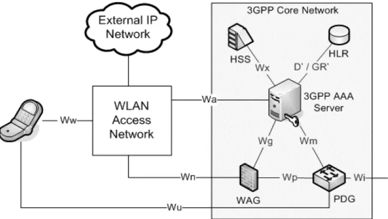
Fig. 1 shows a reference model that allows the UE to access to services provided by the UMTS home network through a WLAN. Two new elements, WLAN Access Gateway (WAG) and Packet Data Gateway (PDG), are added to the UMTS PS core network.
In order to access 3G-based services from WLAN, a WLAN UE first needs to authenticate itself with a 3GPP AAA Server in the 3G PS core
network4. Then, it sends a request to a WAG, indicating that it wants to access to certain APN (Access Point Name). The WAG, based on the APN demanded, will choose an appropriate PDG and establish a tunnel with this PDG. Hence, a tunnel is created between the WLAN UE and a PDG with the WAG at the middle. Across this tunnel, all communications between WLAN UE and the APN will take place (media and signaling).
As WAG is not involved in the handover method presented in this paper, from then on, for the sake of simplicity, WAG will not be mentioned in the tunnel creation procedure between WLAN UE and PDG. Instead, we assume that a request to create a tunnel is sent directly from WLAN UE to a PDG.
Seamless handover between UTRAN and WLAN access network
Overview
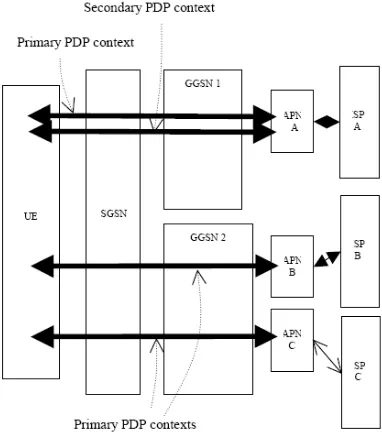
When connected to UTRAN, a UE can be connected to several APNs (Figure 2) and it has one IP address for each APN. The connection to an APN is represented by a primary PDP context, which is stored in the UE, SGSN and GGSN. When connected to WLAN access network, a UE can also be connected to several APNs and has one IP address for each APN but each connection to an APN is represented by a VPN tunnel between the UE and a PDG.
The handover process presented here will allow a UE to switch from one network to another without service interruption or discontinuity. This is accomplished by mapping a PDP context in UTRAN to a VPN tunnels in WLAN access network, so that all connections to APNs and IP address of the UE for each connection will be kept unchanged when the UE changes from one network to the other. As showed in figure 3, the handover mechanism described in the next sections requires that the WLAN access network must be connected to a PDG in the same UMTS core network as the GGSN serving the UE.
Extension to GTP protocol
paper requires the support of an extended GTP protocol at GGSNs and PDGs. This extension will allow a GGSN to keep a list of SGSNs and PDGs serving a UE (maximum 2 elements in the list), called “forwarding list”, for the handover purpose. The GGSN will forward packets destined to the UE to all elements in the list. The differences between standardized GTP and our extended version lie in the UPDATE PDP CONTEXT message. The UPDATE PDP CONTEXT message in our proposed version contains a special Extension Header Type in the message header. GGSNs that support this GTP extension will recognize that Extension Header and add the sender of this message to the “forwarding list”, so that the sender will receive a copy of ever y future packet sent to the corresponding UE. Old GGSNs that support only standard GTP will send back a “Suppor ted Extension Headers Notification”6 message to indicate that it does not support the extension header.
Seamless handover from UTRAN to WLAN access network
Before the handover, UE is connected to GGSN through SGSN and UTRAN (Figure 3). When the UE comes into an area covered by a suitable WLAN access network (a WLAN that is connected
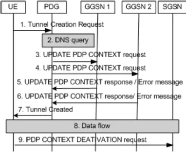
to a PDG in the same core network as the GGSN serving the UE), the handover process can begin. The handover can be initiated by the user when he/ she wants a larger bandwidth or by the UE when the UTRAN signal is weak or for specific services. How a UE can decide when to start the handover procedure is out of scope of this paper, please refer to7 for more details. When a handover is to be initiated, the UE will connect to the WLAN and authenticate itself with a 3GPP AAA Server in the UMTS core network, following the procedures specified in². The procedure showed in figure 4 begins when the authentication is done. The different messages are exposed below:
Tunnel Creation request
The UE sends requests to create VPN tunnels to the PDG. Each VPN tunnel will be used to replace an existing primary PDP context between the UE and a GGSN. Each Tunnel Creation request contains the APN and the IP address of the UE extracted from the coresponding primary PDP context.
DNS query
The PDG uses Domain Name Service (DNS) to find out which GGSNs are connected to the requested APN.
Messages exchanged between PDG and GGSNs The PDG sends a UPDATE PDP CONTEXT request with a special Extension Header to each of the GGSNs found in step 2. On reception of this request, GGSNs that support extended GTP will reply with an UPDATE PDP CONTEXT response message, which indicates whether the PDG is successfully added to the “forwarding list” of the associated PDP context at that GGSN, or the PDP context is not found at that GGSN. Old GGSNs that do not support our GTP extension will reply with “Suppor ted Extension Headers Notification” message. In the case where the PDG is added to the “forwarding list”, the GGSN will forward all subsequent packets destined to the UE to the PDG right after the UPDATE PDP CONTEXT response message is sent. Packets sent from the UE to PDG are also tunneled to the GGSN. If the tunnel creation request (message 1) does not contain a fixed IP address, or if no PDP context is found at GGSNs, the PDG will treat the request as specified2.
Tunnel created
The PDG informs the UE that the request to establish a VNP tunnel has been accepted. The packets that are forwarded to the PDG from the GGSN will be sent to the UE through this new tunnel.
Data flow
Data between UE and APN are now exchanged through two different paths, one across UTRAN and the other across WLAN. These two paths have the same 2 endpoints: the UE and the GGSN. It’s the responsibility of the GGSN and the UE to drop duplicate packets. (UE deals with packet duplication on the downlink and GGSN deals with that on the uplink. See section 4).
PDP context deactivation
When the connection to the APN is assured through the WLAN. The UE will close down the connection to the same APN on the UTRAN side.
Seamless handover from WLAN access network to UTRAN
Before the handover is initiated, UE is connected to UMTS core network via WLAN access network. When the UE comes into the area covered by UTRAN and decides that a handover should be
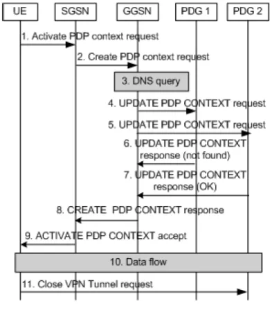
carried out (again, this decision can be taken by the UE or by the user), it will perform GPRS attach procedure with a UTRAN following the procedures specified5. Once the UE is GPRS attached, the procedures in figure 5 will begin. Each message in the figure 5 is developed below:
Activate PDP Context request
The UE sends Activate PDP Context requests to the serving SGSN, each request corresponds to an existing VPN tunnel between the UE and a PDG. An Activate PDP Context request contains, among other information, APN and IP address of the UE.
Create PDP Context request
SGSN continues the procedure to activate a PDP context5 by sending a Create PDP context request to the GGSNs serving the APN.
DNS query
The GGSN uses Domain Name Service (DNS) to find out which PDGs are connected to the requested APN. The GGSN asks each of the PDGs found in step 3, by sending them the UPDATE PDP Context Request (which contains a special Extension Header), to see if some PDG is serving the connection between the UE and the APN.
Update PDP Context response
The PDG serving the UE with that APN (PDG2 in Figure 5) will reply to the GGSN with an UPDATE PDP Context response message, which indicates that subsequent packets destined to the UE will be forwarded to the GGSN. In addition, the GGSN will also tunnel packets sent from the UE to the PDG2. In the UPDATE PDP Context response message sent to the GGSN, the PDG1 tells the GGSN that it is not serving that UE. If no PDG is serving that UE, GGSN will continue by using procedures specified5.
Create PDP context response
The GGSN sends a Create PDP Context response message to the SGSN, reporting that the PDP context has been created. This message is sent as if the GGSN has followed procedures5 to create this PDP context.
Activate PDP context accept
SGSN informs the UE that its request to activate a PDP context with the APN is accepted.
Data flow
Data is now sent to and from the UE by 2 different paths, one across WLAN and the other across UTRAN.
Close VPN Tunnel request
When the connection is assured through UTRAN, the UE sent a request to close down the connection on the WLAN side.
Implementation of the proposed mechanism Researcher had built a test platform to validate our work. As depicted in figure 6, the system consists of 5 PCs connected to the Internet, two different LANs and a WLAN. The SGSN, GGSN and PDG are all simulated by software. UE connects to SGSN through the Internet, which is considered as an UTRAN. The shaded area in the figure is UMTS core network. The GGSN has a connection to an external IP network (LAN2), to which connected a server that the UE wants to access.
In our test, we first initiate a session (FTP or RTP) between UE and the server, then we force the UE to carry out the handover back and forth between two access networks. Researcher also fix
Fig. 3: Data sent to/from UE through 2 different paths
the connection with original network is torn down so that all traffic to and from UE is routed across the new access network.
The result shows that the handover from UTRAN to WLAN is completely seamless to user, regardless of whether the session in progress is FTP or RTP. However, in the handover from WLAN to UTRAN, where the bandwidth is generally reduced as the UE changes the access network, FTP sessions are temporarily suspended right after the handover and then they are gradually resumed. This is due to congestion control mechanism of TCP (Transmission Control Protocol) and is explained12.
The function to filter duplicated packets on the UE can be implemented in many ways, with the tradeoff between speed and exactness, i.e. some algorithm may require less memory and is faster than the others but will make more mistakes in recognizing duplication of packets. Here, in our test, we implement this function using a simple algorithm (at the cost of high packet dupplication rate) so not to impose a heavy charge on the UE, which usually has only a limited memory and computing capacity. Because duplication of packet is an event that might happen at any time with IP protocol, it is already taken into account by reliable transport protocols at higher layers. Hence, in our test, we even sometimes disable the filter function and found that packet dupplication did not affect existing FTP and RTP sessions in any way.
Related work
A good introduction to vertical handover can be found7. Performance issues and latency components of vertical handover are very well analyzed12. MIP and SIP based solutions were proposed for mobility management in GPRS-WLAN integrated system but these solutions do not support seamless handover9. Earlier studies implemented a testbed to study use of MIP for the GPTS-WLAN vertical handover11. A method designed to support seamless handover based on SCTP protocol is presented10.
Inside 3GPP, work to integrate 3G and WLAN networks is being done in Release 6. Although architecture for accessing UMTS services from WLAN access network was outlined, no
Fig. 5: Handover for one VPN tunnel
Fig. 6: Experiment platform
solutions for intersystem handover have been addressed.
CONCLUSIONS
WLAN is at the same PS core network as the GGSN serving the UE is not very restrictive. It would, in addition, guarantee the quality of the path between PDG and GGSN, which is a portion of the new path between the APN and the UE, hence guarantee the quality of the new path.
The choice of GTP as tunneling protocol between GGSN and PDG is justified by the fact that it reduces the complexity added to GGSN in order to support the handover. Nonetheless, any other tunneling protocol can also be used for this purpose.
This method does not take care of QoS aspects because there is not yet a QoS enabled
WLAN. Nevertheless, once the WLAN access network is QoS enabled, this method is easily extensible to suppor t QoS aware seamless handover. That would be achieved by mapping between a primary PDP context on the UTRAN side and a QoS enabled VPN tunnel on the WLAN side.
For the similarity features between GGSN and PDG, some GGSN-PDG combined in a single physical entity are about to be available on the market. If the mechanism described here is supported by these “2 in 1” GGSNs, the tunnel and signaling between GGSN and PDG can be avoided, which will facilitate the implementation and lead to better performance of the proposed handover mechanism.
1. 3GPP TS 23.234 v6.0.0, Release 6 “3GPP System to WLAN Interworking – System description”.
2. 3GPP TS 24.234, Release 6 “3GPP System to WLAN Interworking – UE to Network protocols”.
3. 3GPP TS 29.234, Release 6 “3GPP System to WLAN Interwor king – Stage 3 Description”.
4. 3GPP TS 33.234, Release 6 “Wireless Local Area Network (WLAN) interworking security”. 5. 3GPP TS 23.060, Stage 2, Release 6 “General Packet Radio Service – Services description”.
6. 3GPP TS 29.060, Realease 6 “GPRS Tunnelling Protocol (GTP) across the Gn and Gp interface”
7. Raynolds, P. “Mobility management for the suppor t of handover within a heterogeneous mobile environment” 3G Mobile Communication Technologies (2000).
8. M. Riegel and M. Tuexen, “Mobile SCTP,” draftriegel- tuexen-mobile-sctp-03.txt, work in progress (2003).
9. V. K. Varma, et al., “Mobility management in integrated umts/wlan networks,” in Proc. IEEE ICC (2003).
10. Lima et al. “A new method to support UMTS/ WLAN ver tical handover using SCTP” Vehicular Technology Conference, 2003. VTC 2003-Fall. 2003 IEEE 58th, 3 (2003). 11. J. W. Floroiu, et al. “Seamless Handover in
Terrestrial Radio Access Networks: A Case Study” Communications Magazine, IEEE, 41(11): (2003).
12. Rajiv Chakravorty, et al. “Performance Issues with Vertical Handovers - Experiences from GPRSCellular and WLAN Hot-spots Integration” Second IEEE International Conference on Pervasive Computing and Communications (2004).