Tribology in Industry
www.tribology.rsA Short Review on Frictional Contact Stress
Distribution in Involute Gears
S.S. Patil
a, S. Karuppanan
b, I. Atanasovska
ca Department of Mechanical Engineering, Manipal University Jaipur, 303007, Jaipur, India,
b Department of Mechanical Engineering, Universiti Teknologi PETRONAS, 32610 Bandar Seri Iskandar, Perak, Malaysia,
c Mathematical Institute of the Serbian Academy of Sciences and Arts Kneza, Mihaila 36, 11001 Belgrade, Serbia.
Keywords: Contact Stress
Finite Element Method Gear Testing
Contact mathematical models Spur gear
Helical gear
A B S T R A C T
In this paper, the gear contact evaluation models developed using various methods have been discussed. The new experimental and numerical methods have been presented. The research papers are classified into frictionless and frictional contact stress analysis and subdivided into experimental and finite element models. This paper will provide researchers with various information and huge literature data on the described subject. It serves as the rapid retrieval of data related to gear contact stress evaluation. Furthermore, a comprehensive discussion focusing on the customized experimental test rig (Gear Dynamic Stress Test Rig) has been done. Also, the finite element (FE) results showing the variation of contact stresses with and without friction, along the contact path has been shown. The FE results revealed that the contacting stresses between the gears increased significantly for different parallel axis gear, for a given coefficient of friction rise considered in the study.
© 2019 Published by Faculty of Engineering Corresponding author:
S.S. Patil
Department of Mechanical Engineering, Manipal University Jaipur,
303007, Jaipur, India.
E-mail: santosh045@gmail.com
1. INTRODUCTION
Gear contact problems have been studied for many decades, but still many stress affecting parameters are not compressively examined. The contact problem of two elastic cylindrical bodies was first solved by Heinrich Hertz in 1882 and it became the most notable classical contact mechanics theory. This classical solution has been the foundation for all modern-day problems in contact mechanics. Another premier scientist to experiment with contact pressure between two deformable
bodies was Archard [1]. His work led to many of the modern day techniques and formulations on contact analysis [2,3]. His theory was the extension of the works carried out by Hertz. The contact pressure/stress is a function of the contacting curvature radius and the material properties in contact unlike the bending stress, which is a function of the shape and geometry of the gear tooth [4]. There has been many research into the contact pressure between a spur gear and pinion, while recent research also shows works on helical gear pairs.
R
EV
IE
The study of contact mechanics in gears has been of great interest, as the gears which are used in many applications, are subjected to repeated loadings on tooth surface. Due to such loadings, the contact stress variations occur on the gear flanks. Hence, it is necessary to take utmost care so that these contact stress variations do not exceed the surface fatigue limit of the gear material. If in case, the stress variations exceed the surface fatigue limit, then pitting failure would occur on the gear surfaces. The pit is a small material dislodged region due to the high surface contact stresses. There are mainly two types of pitting, initial pitting and the other one is progressive or destructive pitting. These small pits multiply slowly and soon spread to adjacent regions until the gear tooth surface is completely covered with these pits. Subsequently, higher loading results in more pitting which leads to fracture of already weakened tooth [5]. Fracture of pitted gear tooth also occurs after many numbers of mesh cycles. The contact stresses between meshed gears also indirectly lead to scuffing and fatigue failure of gear tooth.
It is understood that friction between gear mesh greatly affects the surface contact stresses of gears. However, so far, there isn’t any efficient method available to conduct precise analyses of gear contact stresses with friction. Frictional contact problems are rather complicated from the mathematical and experimental point of view. With recent developments, finite element method (FEM) has gained importance and is being used extensively to evaluate problems related to gear contact, with considerably better stress estimation [6]. The FEM is often used to
analyze the stress state of an elastic body with complicated geometry, such as a gear.
This paper would serve gear designers and researchers as a source of literature on gear contact stress analysis with and without friction. Frictional gear contact stress evaluation has been the major challenge. Finite element (FE) technique has been utilized to solve this nonlinear frictional problem and a new idea of friction factor for gear contact stress evaluation has been proposed in recent literature [7].
2. CONTACT ANALYSIS OF INVOLUTE
PARALLEL AXIS GEARS
Contact analysis of parallel axis gears can be divided into experimental and numerical (finite element) methods. Further, FEMs are classified into two categories, FE models without considering friction and FE models considering friction.
2.1 Experimental models
Experimental models considered in this review are compared in Table 1. The summary of all the models are presented. The works on gear contact stress measurement are also discussed.
Rebbechi et al. [10] used the strain gages at two successive gear teeth to measure the dynamic friction forces at gear contacts. The measured forces were used to evaluate the coefficient of friction that exists between the contacting teeth. The setup had a single tooth - loading gear and the strain gages were implanted on the output gear’s root fillets.
Table 1. Comparison of Experimental Evaluation of Contact Stresses.
Author Title Methodology Summary
Guingand et al. (2004) [8]
Three-Dimensional Quasi-Static Analysis of Helical Gears Using the Finite Prism Method
Experimental and Finite Prism Method
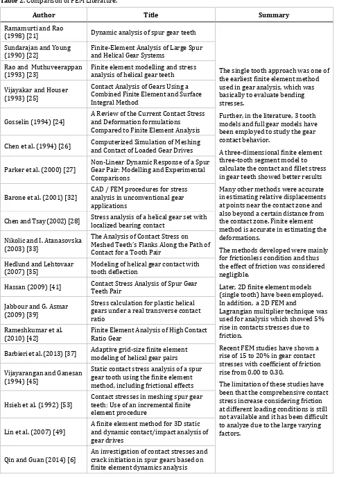
The earlier literatures on experimental gear testing provide a general contact stress measurement and many cases are not suitable to evaluate frictional losses. The evaluation of frictional contact stresses is necessary, as friction significantly deviates the gear contact stresses. There was a
customized gear setup GDSTR (shown in Figure 1) which attempted to evaluate the frictional contact stresses, but for a limited torque and speed. Jebur et al.
(2011) [9]
Numerical and Experimental Dynamic Contact of Rotating Spur Gear
Numerical and Experimental Method
Rebbechi et al.
(1996)[10] Measurement of Gear Tooth Dynamic Friction Experimental Method
Muraro et al. (2012) [11]
The Influence of Contact Stress Distribution and Specific Film Thickness on the Wear of Spur Gears During Pitting Tests
Twin Disc Test Method
Kleemola and Lehtovaara (2009) [12]
Experimental simulation of gear
contact along the line of action Twin Disc Test Method
The rig consisted of a simple gearbox powered by a 150 kW variable speed electric motor, with an eddy current dynamometer to provide power absorption on the output. The measured dynamic friction loads revealed that friction coefficients were in the range of 0.04 to 0.06 and friction coefficients increased at lower sliding speeds. This measuring technique offered a great potential to study variation of friction coefficient in gear mesh along the path of contact.
Muraro et al. [11] performed experimental tests using image analysis on spur gear to evaluate pitting, studied the wear thickness and influence of contact stress distribution on gears. Friction was included and the coefficient of friction varied. A blunt frictional contact measuring setup named twin-disc experimental setup was utilized. Kleemola and Lehtovaara [12] investigated the contact behaviour of a spur gear using this setup. The experiments were carried out in the presence of friction coefficient on the twin-disc setup and the contact pressure was measured at various points along the contact path. The friction coefficients between the disc using lubricants (Mineral and PAO oil) were determined and the values were generally found in the range of 0.03 to 0.07. Twin-disc measurements give local information of gear contact along the line of action. The contacts can include friction and these experiments proved to be fast and economical, but are not real gear contacts. In another study, Velex and Cahouet [13] also conducted experimental studies along with numerical investigation on the influences of
friction on gear tooth dynamics. The numerical study was based on a FE model. Several iterative algorithms using time-step iteration method were aimed at satisfying all the contact conditions and to solve the equations of motion. They observed that the gear friction contribution was mainly at low to medium speeds and were almost negligible at high speeds. The results obtained also showed the significance of including tooth friction in the study and its contribution to gear dynamics. Another experimental setup in the classification of contact solving techniques is Gearbox Dynamic Simulator (GDS) which was developed by Spectraquest to evaluate contact behaviour and various other parameters.
validated with FE approach. The setup has a torque capacity of 100 Nm and is suitable for lower speed testing (up to 30 rpm). The detailed measuring process has been explained in the reference [20].
2.2 Gear Finite Element Models Without
Considering Friction
The papers using FEM to evaluate gear contact stresses, without considering friction in-between the gear contact is discussed in this subsection.
In 1988, Ramamurti and Rao [21] presented a FE model to analyse the stresses in spur gear teeth. This 2D one tooth model was used for the analysis. By using the cyclic symmetry of the gear teeth loading, the stress distribution in the adjacent teeth could be computed. This single tooth approach was one of the earliest FEM used in gear analysis. However, this was not a comprehensive approach to evaluate contact stresses, as single tooth analysis is mainly carried out for bending stress evaluation. Later in 1990 Sundarajan and Young [22] and in another work Rao and Muthuveerappan [23] developed a 3D finite element 3 tooth model to calculate contact and fillet root stresses in gears. The developed analysis method and pre-processing technique significantly improved the accuracy in stress calculation and reduced the human effort involved in the analysis. Even if any of the parameters (e.g. misalignment) were altered, most of the stiffness matrices remained the same and were not recalculated, this saved calculation time. In the later study, the combined effect of face width and helix angle on the principal root stresses of helical gears were computed at different positions on the contact line. The comparative study of the current contact stress and deformation formulations with that of FE analysis was presented by Gosselin et al. [24]. The outcome of the work showed that the contact deformations differed from 20 % to 150 % between the FEM and analytical approaches. Since these percentage differences were higher, the developed FE approach was inappropriate and had required justifications for the high differences. The FE model in this particular study must be revisited and also refinement of the mesh density is necessary for better results.
The contact conditions at the gear tooth flanks are very sensitive, which indicate that the FE
mesh must be highly refined at the contact zone. However, it is not recommended to have the same level of refinement throughout the model, in order to optimize the computational requirements and time. Vijayakar and Houser [25] introduced a combined finite element and surface integral method for the contact analysis in gears. The approach of fine mesh at the contact zone and moderately coarse mesh away from the contact zone gave good results at a faster rate and used fewer resources. The same approach needs to be considered in all FEM, where high mesh density needs to be maintained at the area of interest. Similar FEM models were proposed by Chen et al. [26], Parker et al. [27], Chen and Tsay [28], Wang and Howard [29], Li [30], Chacon et al. [31] and Barone et al. [32]. The FE procedure to investigate the contact and bending stresses of a parallel axis gear set require appropriate boundary conditions. Various authors proposed a FE model with slight variation in CAD model preparation and meshing. The FE models were either validated theoretically or experimentally. Nikolic and Atanasovska [33] proposed a similar FE model to analyse the helical gears and the results were validated using analytical calculations. The FEM results matched well with the analytical calculations and hence the FE model can be very well employed to evaluate the gear contact stresses.
Brauer [34] studied conical involute gears using a mathematical formulation, which was also capable in representing three other types of involute gear. Thus, finite element models of involute gears were created using these equations and the intervals of the surface parameters. Similarly, helical gears can be represented by letting cone angle be equal to zero. If both cone angle and helix angle are made zero, the equations would represent spur gears. The formulation aided in optimized finite element meshing for different types of gears, right from spur to conical type gears.
deflection which includes tooth foundation flexibility with tooth bending and shearing. The model avoided large mesh sizes by combining the contact and structural analysis. The capability of different local contact calculation methods was also studied. Stoker [36] used both the 2D and the 3D analysis model to investigate the contact problem. He provided a FE approach to study the spur gear response and wear under non-ideal loading conditions. The developed FE tool predicted the rise in spur gear stresses for a non-ideal loading condition. The wear also increased with non-ideal loading, increasing the stresses in the gear pairs. An average of 45 % rise in equivalent stresses was observed for non-ideal loading. Hence, the non-ideal loading is detrimental for the smooth power transmission, as it increased the contacting stresses. Also, Barbieri et al. [37] described a method to carry out loaded tooth contact analysis (LTCA) on generic helical gear pairs. The method involved a 3D nonlinear FEM of helical gears.
Jabbour and Asmar [38] focused their analysis on plastic helical gears. They proposed a mathematical model to derive the non-uniform load distribution of the helical gears. The presented model represented the real number of tooth pairs in contact based on the real contact ratio calculations. This model helped in analysing the tooth bending stress and the contact stress distributions along the contacting area. The results obtained were validated with a computer program. In yet another work, Jabbour and Asmar [39] developed a method for the calculation of tooth stresses (both contact and root) for metallic spur and helical gear(s). The method was based on the discretization of the helical gear into an infinite number of spur gears. This method was used to calculate the stress distribution at the tooth root and the contact stress along the contact lines of a pair of spur and helical gears. The results of the presented method were confirmed with the FE calculations. Slogen [40] developed a computer program called the Transmission3D (for Vicura AB), as an analytical tool for analysing the contact mechanics of spur and helical gears. A mechanical standard and a computational method were used to evaluate the performance of the developed computer program. In addition to the development of a computer program, the focus of the work was also on the investigation
of how gears can be designed in order to improve the contact durability.
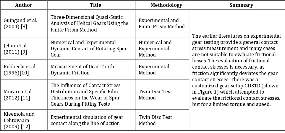
Recently, the FE approach has become an important tool to study the gear contact stresses. The above researchers have shown the importance of the FE approach over the other methods, also pointing to the usefulness of the FE approach. The researchers like Hassan [41], Rameshkumar et al. [42], Hwang et al. [43], Cheng and Tsay [28] have shown the general spur gear contact stress trend, which needs to be achieved before proceeding any further. The general contact stress for a spur gear along the contact path can been represented and is as shown in Fig. 2. The ratio of active stress at any contact point
𝜎𝐻𝑥 and active stress for contact at the pitch
point σHC can be used to monitor the active stress variations on the tooth flanks. The normalized stress 𝜎𝐻𝑥
𝜎𝐻𝐶 is represented and the
detailed calculation can be found in [7]. The contact path along which both the factors were presented was generalised (distance of contact was divided by the base pitch) and a dimensionless factor 𝑦𝑖
𝑝𝑏 was deduced.
Fig. 2. General contact stress trend for a spur gear along the contact path [7].
contact stresses varied for different conditions and did not follow any trend. Hence, a generalised prediction of contact stress for a normal working gear pair is difficult to be made with these individual studies. A critical FE study need to be performed to derive a generalised contact stress estimation approach.
It can be seen from the literature above that the output of scientific papers is fast growing in this area. Also, it can be seen that the FE method has been validated with analytical or experimental techniques. The results obtained are promising and good estimates of the real conditions. Thus, FEM has become the prevalent technique used for analysing physical phenomena of gear contact.
2.3 Gear Finite Element Models with Friction
Literatures regarding the FEMs on different types of gears and gear drives published during 1997 to 2006 have been listed in a bibliography paper by Prasil and Mackerle [44]. Few other papers have been included with summary in Table 2 and discussed in the following paragraphs.
Vijayarangan and Ganesan [45] studied gear using 2D FE model with Lagrangian multiplier to evaluate the contact stress of a gear pair under
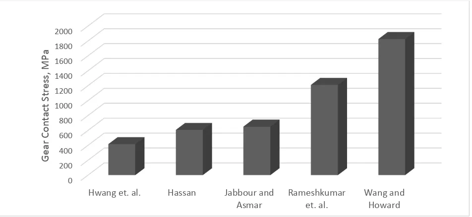
static conditions. This study was amongst the earliest study which considered the use of FEM for gear contact and gear root stress analysis. The model generated was a single gear tooth to estimate the tooth contact stresses. The results included friction coefficient varying from 0 to 0.3 and the stress increment of 5% was observed. In 1988, Vijayakar et al. [46] used a simplex type algorithm in 2D FE models, instead of Lagrangian multiplier algorithm, to include frictional contact conditions. The study showed a rise in contact stresses with friction, which was expected. The FE model proposed by Vijayarangan and Ganesan [45] was used by Hsieh et al. [47] to examine the contact stresses in a meshing spur gear tooth pair. They carried out analysis using incremental FE procedure, which simultaneously determines the stresses and the contact area between meshing teeth. The analysis assumed elastic condition and included frictional effects, with friction forces assumed to follow the Coulomb’s law of friction. Hertz theory was used for validation and correlation of the FE procedure and the results showed excellent agreement. The FE model used in this study was a single tooth model as shown in Fig. 4. The results demonstrated the feasibility and the practicality of using the FEM for gear stress calculations. The presence of friction in between the contacting surfaces has increased the contact stresses.
Fig. 3. Maximum contact stresses observed from different literature. 0
200 400 600 800 1000 1200 1400 1600 1800 2000
Hwang et. al. Hassan Jabbour and
Asmar
Rameshkumar et. al.
Wang and Howard
Gear
Contact
Stress,
MP
Fig. 4. FE model of a spur gear tooth contact at pitch point [47].
A 3D FE model would have been better in evaluating contact stresses. The works using 3D FE model with friction are few and not comprehensive. Some of the studies conducted using this approach is discussed below.
Liu et al. [48] analysed complex contact problems by a contact model of a single asperity on rough tooth surface under normal and side contact, which was based on Hertz theory and Coulomb’s friction law. This model is a good choice for future study on engaging mechanism of the micro-surface of gear teeth, friction, wear and micro elastohydrodynamic lubrication. Li et al. [49] presented an approach for generating mesh of gear drives for any mating position and developed an automatic modelling programme for tooth analysis. They proposed a FEM for 3D contact/impact problem from the derivation of flexibility matrix equation in contact region. The proposed method is used for both static and dynamic loading conditions. In static loading conditions, tooth load distribution and mesh stiffness results were evaluated and dynamic gear behaviour was also simulated. The FE model used in this method was a three-tooth segment model. The mesh stiffness results from this research showed good agreement with the results calculated using the conventional method.
In the study conducted by Qin and Guan [6], contact stress analysis and fatigue crack initiation prediction were applied to a pair of spur gear in a high speed diesel engine. The Hertzian theory and FEM were employed to investigate the surface and subsurface stresses
of the gear tooth. The effects of speed and friction were analysed in the study. It was found that the von Mises stresses increased with increasing friction which altered the shear stress cycles. Hence, the surface pitting was formed with the increase of friction. Surface pitting and micro-pitting on gear teeth flanks can be better understood using previous studies [50-52]. It was also found that the stress pit points near the engagement and recess areas were very high, and with the increase of speed the stresses fluctuated more severely and these pit zones became more dangerous. This resulted in lower fatigue lives compared to that of static contact conditions. Abaqus/Explicit was employed to simulate the process from engagement to recess of a pair of spur gear teeth in the diesel engine at low speed and high speed, respectively.
It can be observed from this section that the frictional inclusion in gear contact study is sparse. Few works [50-52] which have tried to predict the frictional effects are listed and they have shown the level of complications involved. Also numerous assumptions were made to mathematically study the frictional variations in gears. The experimental approach conducted was also for a particular case and could not be considered for generalised case.
The FE approach to study friction in gear contact studies used either a single tooth approach or a 2D model, both of which have limitation in predicting accurate results. Hence, a more appropriate 3D FE approach which can estimate the real gear friction conditions needs to be implemented to study the frictional gear contact problem. Thus an improved 3D FEM approach has been proposed in the following literature.
Table 2. Comparison of FEM Literature.
Author Title Summary
Ramamurti and Rao
(1998) [21] Dynamic analysis of spur gear teeth
The single tooth approach was one of the earliest finite element method used in gear analysis, which was basically to evaluate bending stresses.
Further, in the literature, 3 tooth models and full gear models have been employed to study the gear contact behavior.
A three-dimensional finite element three-tooth segment model to calculate the contact and fillet stress in gear teeth showed better results Many other methods were accurate in estimating relative displacements at points near the contact zone and also beyond a certain distance from the contact zone. Finite element method is accurate in estimating the deformations.
The methods developed were mainly for frictionless condition and thus the effect of friction was considered negligible.
Later, 2D finite element models (single tooth) have been employed. In addition, a 2D FEM and
Lagrangian multiplier technique was used for analysis which showed 5% rise in contacts stresses due to friction.
Recent FEM studies have shown a rise of 15 to 20% in gear contact stresses with coefficient of friction rise from 0.00 to 0.30.
The limitation of these studies have been that the comprehensive contact stress increase considering friction at different loading conditions is still not available and it has been difficult to analyze due to the large varying factors.
Sundarajan and Young
(1990) [22] Finite-Element Analysis of Large Spur and Helical Gear Systems Rao and Muthuveerappan
(1993) [23] Finite element modelling and stress analysis of helical gear teeth Vijayakar and Houser
(1993) [25]
Contact Analysis of Gears Using a Combined Finite Element and Surface Integral Method
Gosselin (1994) [24] A Review of the Current Contact Stress and Deformation formulations Compared to Finite Element Analysis Chen et al. (1994) [26] Computerized Simulation of Meshing and Contact of Loaded Gear Drives
Parker et al. (2000) [27] Non-Linear Dynamic Response of a Spur Gear Pair: Modelling and Experimental Comparisons
Barone et al. (2001) [32] CAD / FEM procedures for stress analysis in unconventional gear applications
Chen and Tsay (2002) [28] Stress analysis of a helical gear set with localized bearing contact
Nikolic and I. Atanasovska (2003) [33]
The Analysis of Contact Stress on Meshed Teeth’s Flanks Along the Path of Contact for a Tooth Pair
Hedlund and Lehtovaar
(2007) [35] Modeling of helical gear contact with tooth deflection Hassan (2009) [41] Contact Stress Analysis of Spur Gear Teeth Pair
Jabbour and G. Asmar (2009) [39]
Stress calculation for plastic helical gears under a real transverse contact ratio
Rameshkumar et al.
(2010) [42] Finite Element Analysis of High Contact Ratio Gear Barbieri et al. (2013) [37] Adaptive grid-size finite element modeling of helical gear pairs
Vijayarangan and Ganesan (1994) [45]
Static contact stress analysis of a spur gear tooth using the finite element method, including frictional effects
Hsieh et al. (1992) [53] Contact stresses in meshing spur gear teeth: Use of an incremental finite element procedure
Lin et al. (2007) [49] A finite element method for 3D static and dynamic contact/impact analysis of gear drives
In another work, Patil et al. [7] proposed a new idea of including a friction factor during gear contact stress calculations. The idea of friction factor and its evaluation was introduced and the application of this factor into the contact stress calculation along the tooth contact for different involute gear pairs was shown. Friction factor was developed by evaluating contact stresses with and without friction for different gear pairs. A FE software (ANSYS) and Lagrange Multiplier algorithm were used to evaluate the contact stresses in gears. The FE models were constructed for spur gear, 5, 15, 25 and 35 deg. helical gears. The FE results of contact stresses have been presented and are as shown in Figs. 5-9 for the spur gear, 5, 15, 25 and 35 deg. helical gears, respectively.
Fig. 5. Spur gear normalized stress plot along the contact path for different coefficient of friction.
Fig. 6. Helical gear (5 degree) normalized stress plot along the contact path for different coefficient of friction.
Fig. 7. Helical gear (15 degree) normalized stress plot along the contact path for different coefficient of friction.
Fig. 8. Helical gear (25 degree) normalized stress plot along the contact path for different coefficient of friction.
The characteristic points considered are First Point of Tooth Contact (FPTC), Highest Point of Single Tooth Contact (HPSTC), Pitch Point of Contact (PPC), Lowest Point of Single Tooth Contact (LPSTC) and Last Point of Tooth Contact (LPTC). The coefficient of friction was increased from 0 to 0.3 at random intervals. The FE results showed an increasing trend with increasing coefficient of friction.
The results for spur, 5 degree, 15 degree, 25 degree and 35 degree helical gear pairs showed an increasing trend of the normalized contact stress values with the increasing coefficient of friction values. This is similar to one of the previous studies by Fajdiga [54]. A 15 % increase of contact stress was recorded for a spur gear pair when friction coefficient was increased from 0 to 0.3. Similarly, for 5°, 15°, 25° and 35° helical gear pairs, the contact stress increased by 18 % 22 % 18 % and 18 %, respectively. It was noted from the study that the increase of friction augments the pitting formation, which in turn weakens the tooth surface. This pitted surface increases the contact stresses even more and this process continues. Thus, a proper study on the surface strength is necessary. Based on the results, we can generally predict that the contact stresses in between gear contacts increase in the range of 15 to 22 percent. The hypothesis can be further generalised and is considered true for all set of gear pairs with different loading conditions. The parametric studies were further carried out and the FE results were utilized for the development of friction factor (Kf). The friction factor function can be obtained from the ref. [7].
3. REVIEW SUMMARY
In the aforementioned literatures, various old and recent studies on gear stress analysis have been reviewed. Since gears have a vast application in industries, high performance gears are required to operate at adverse conditions. The high stress concentrations at the contacting point and tooth root of a gear are the main reasons for gear tooth failure. The literature review shows that a considerable amount of research has been done on methods of stress analysis on gear tooth which were developed to improve the accuracy of gear tooth
stress evaluation. Since the local contact stress along the profile of the tooth is higher than that occurring at the root of the tooth and is a primary source of the surface fatigue failure, many studies were focused on contact stress. The literature study related to gear contact stress has been done extensively and it has been systematically presented in groups. The contact stress analysis with friction has been our main consideration. Experimental and FE analysis work are systematically organized. Many recent work [6,36,40,41,43,55–62] on contact stress evaluation shows that FEM is one of the most prominent methods being used in stress analysis of gear tooth. This is due to the development of contact algorithms and their implementation in commercial FEA software in the last few years. In this review paper, an investigation on the gear tooth contact stress for spur and helical gears with involute profile by using various methods have been presented. It has been found that frictional contact stress evaluation had been sparse except the recent studies with proposed frictional contact stress evaluation. Also, the limitations and shortcomings of the experimental models have been highlighted. With the introduction of FEM and with the rise of powerful computing, FEM has been prevalent in recent decade and fast publications have shown promising output of this technique. Lastly, a 3D FEM for frictional contact stress analysis has been discussed. It has shown the importance of including friction in gear contact stress evaluation.
4. CONCLUSIONS
The purpose of this paper is to provide a review on the various gear contact problem solving techniques, applications of mathematical, experimental and FEM in gear contact stress evaluation. The other concluding points of this review paper are:
1. The finite element method (FEM) has emerged as the prevalent technique useful for analysing and understanding the physical phenomena of gear contact mechanics.
3. A new viewpoint of friction factor has been shown in literature for the gear contact stress analysis using FEM. Also, the inclusion of friction factor into AGMA equations has been proposed for effective evaluation of frictional contact stresses in parallel axis gears.
Acknowledgement
S. S. Patil and S. Karuppanan acknowledge the financial support by Universiti Teknologi PETRONAS, Malaysia through URIF (URIF fund with cost centre – 015 3AA B10) and Manipal University Jaipur (Endowment Funding- EF/2017-18/QE04-08). I. Atanasovska gratefully acknowledge the support provided by the Ministry of Education, Science and Technological Development of Republic of Serbia and the Mathematical Institute of the Serbian Academy of Sciences and Arts through the projects OI174001 and TR35029.
REFERENCES
[1] J.F. Archard, Contact of rubbing flat surfaces, Journal of Applied Physics, vol. 24, no. 8, pp. 981-988, 1953, doi: 10.1063/1.1721448 [2] A. Flodin, S. Andersson, Simulation of mild wear
in helical gears, Wear, vol. 241, pp. 123–128, 2000, doi: 10.1016/S0043-1648(00)00384-7 [3] A. Sackfield, A.D. Hills, Some useful results in the
classical Hertz contact problem, The Journal of Strain Analysis for Engineering Design, vol. 18, pp. 101–105, 2007, doi: 10.1243/03093247V182101
[4] R.C. Juvinall, K.M. Marshek, Fundamentals of Machine Components Design, (Ed.): 5th John Wiley & Sons, 2012.
[5] K. Gopinath, M.M. Mayuram. Gear Failure,
NPTEL, IIT-Madras, 2013 at:
http://nptel.ac.in/courses/IIT-MADRAS/
Machine_Design_II/pdf/2_6.pdf
[6] W.J. Qin, C.Y. Guan, An investigation of contact stresses and crack initiation in spur gears based on finite element dynamics analysis, International Journal of Mechanical Sciences, vol. 83, pp. 96– 103, 2014, doi: 10.1016/j.ijmecsci.2014.03.035
[7] S. Patil, S. Karuppanan, I. Atanasovska, A.A. Wahab, Frictional Tooth Contact Analysis along Line of Action of a Spur Gear using Finite Element Method, Procedia Materials Science, vol. 5, pp. 1801–1809, 2014.
[8] M. Guingand, J.P. de Vaujany, Y. Icard, Fast Three-Dimensional Quasi-Static Analysis of Helical Gears Using the Finite Prism Method, Journal of Mechanical Design, vol. 126, no. 6, pp. 1082–1088, 2004, doi: 10.1115/1.1798212
[9] A.K. Jebur, I.A. Khan, Y. Nath, Numerical and Experimental Dynamic Contact of Rotating Spur Gear, Modern Applied Science, vol. 5, no. 2, pp. 254–263, 2011, doi: 10.5539/mas. v5n2p254
[10] B. Rebbechi, F.B. Oswald, D.P. Townsend Measurement of Gear Tooth Dynamic Friction. NASA Technical Report ARL-TR-1165, 1996. [11] M.A. Muraro, U.Reisdorfer Jr., C. Henrique, The
Influence of Contact Stress Distribution and Specific Film Thickness on the Wear of Spur Gears During Pitting Tests, Journal of the Brazilian Soceity of Mechanical Science & Enggineering, vol. 34, no. 2, pp. 135-144, 2012.
[12] J. Kleemola, A. Lehtovaara, Experimental simulation of gear contact along the line of action, Tribology International, vol. 42, no. 10, pp. 1453– 1459, 2009, doi: 10.1016/j.triboint.2009.06.007
[13] P. Velex, V. Cahouet, Experimental and Numerical Investigations on the Influence of Tooth Friction in Spur and Helical Gear Dynamics, Journal of Mechanical Design, vol. 122, no. 4, pp. 515–522, 2000.
[14] M. Åkerblom, Gear Test Rig for Noise and Vibration Testing of Cylindrical Gears, in Proceedings OST-99 Symposium on Machine Design, 1999, pp. 183-189.
[15] A.P. Arun, Gear Test Rig - A Review, International Journal of Mechanical & Mechatronics Engineering, IJMME-IJENS, vol. 14, no. 5, pp. 16-26, 2014.
[16] M.R. Kang, A. Kahraman, An Experimental and Theoretical Study of the Basicity, Journal of Sound and Vibration, vol. 350, pp. 11-29, 2015. [17] R. Keresztes, L. Zsidai, G. Kalacska, M. Ando, R.
Lefanti, Friction of Ploymer/Steel Gear Pairs, Scientific Bulletin, Series C, Volume XXIII, Fascicle: Mechanics, Tribology, Machine Manufacturing Technology, vol. 23, pp. 63–72, 2009.
[18] J. Wei, A. Zhang, P. Gao, A study of spur gear pitting under EHL conditions: Theoretical analysis and experiments, Tribology International, vol. 94, pp. 146–154, 2016, doi: 10.1016/j.triboint.2015.08.037
[20] S.S. Patil, S. Karuppanan, I. Atanasovska, Experimental measurement of strain and stress state at the contacting helical gear pairs. Measurement, vol. 82, pp. 313–322, 2016, doi: 10.1016/j.measurement.2015.12.046
[21] V. Ramamurti, M. Ananda Rao, Dynamic analysis of spur gear teeth, Computers & Structures, vol. 29, no. 5, pp. 831–843, 1988.
[22] S. Sundarajan, B.G. Young, Finite-Element Analysis of Large Spur and Helical Gear Systems, Journal of Propulsion and Power, vol. 6(4), pp. 451–454, 1990, doi: 10.2514/3.25456
[23] C. R. M. Rao, G. Muthuveerappan, Finite element modelling and stress analysis of helical gear teeth, Computers & Structures, vol. 49, no. 6, pp. 1095–1106, 1993.
[24] C. Gosselin, A Review of the Current Contact Stress and Deformation Formulations Compared to Finite Element Analysis, in International Gearing Conference, Newcastle, UK, 1994. [25] S.M. Vijayakar, D.R. Houser, Contact Analysis of
Gears Using a Combined Finite Element and Surface Integral Method, Gear Technology, Magazine issue July/August, pp. 26–33, 1993. [26] J.S. Chen, F.L. Litvin, A.A. Shabana, Computerized
Simulation of Meshing and Contact of Loaded Gear Drives, in International Gearing Conference, Newcastle, UK, 1994.
[27] R.G. Parker, S.M. Vijayakar, T. Imajo, Non-Linear Dynamic Response of a Spur Gear Pair: Modelling and Experimental Comparisons, Journal of Sound and Vibration, vol. 237, pp. 435–455, 2000, doi: 10.1006/jsvi.2000.3067
[28] Y.-C. Chen, C.B. Tsay, Stress analysis of a helical gear set with localized bearing contact, Finite Elements in Analysis and Design, vol. 38, no. 8, pp. 707-723, 2002, doi: 10.1016/S0168-874X(01)00100-7
[29] J. Wang, I. Howard, Finite Element Analysis of High Contact Ratio Spur Gears in Mesh, Journal of Tribology, vol. 127, pp. 469-483, 2005, doi: 10.1115/1.1843154
[30] S. Li, Finite element analyses for contact strength and bending strength of a pair of spur gears with machining errors, assembly errors and tooth modifications, Mechanism and Machine Theory, vol. 42, no. 1, pp. 88–114, 2007, doi: 10.1016/j.mechmachtheory.2006.01.009
[31] R.D. Chacón et al, Analysis of Stress due to Contact between Spur Gears. in 9th WSEAS International Conference on Computational Intelligence, Man-Machince Systems and Cybernetics (CIMMACS ’10) Merida, Venezuela, 2010, pp. 216-220.
[32] S. Barone et al, CAD / FEM procedures for stress analysis in unconventional gear applications, International Journal of Computer Applications in Technology, vol. 15, no. 1, pp. 1-11, 2001. [33] V. Nikolic, I. Atanasovska, The Analysis of
Contact Stress on Meshed Teeth’s Flanks Along the Path of Contact for a Tooth Pair, Facta Universitatis, vol. 3, pp. 1055–1066, 2003. [34] J. Brauer, A General Finite Element Model of
Involute Gears, Finite Elements in Analysis and Design, vol. 40, pp. 1857–1872, 2004, doi: 10.1016/j.finel.2004.02.002
[35] J. Hedlund, A. Lehtovaara, Modeling of helical gear contact with tooth deflection, Tribology International, vol. 40, no. 4, pp. 613–619, 2007,
doi: 10.1016/j.triboint.2005.11.004
[36] K.C. Stoker, A Finite Element Approach to Spur Gear Response and Wear Under Non-Ideal Loading, Master’s thesis, University of Florida, Florida, 2009.
[37] M. Barbieri, A. Zippo, F. Pellicano, Adaptive grid-size finite element modeling of helical gear pairs, Mechanism and Machine Theory, vol. 82, pp. 17-32. 2014.
T. Jabbour, G. Asmar, Stress calculation for plastic helical gears under a real transverse contact ratio, Mechanism and Machine Theory, vol. 44, no. 12, pp. 2236–2247, 2009, doi: 10.1016/j.mechmachtheory.2009.07.003
[38] T. Jabbour, G. Asmar, Tooth stress calculation of metal spur and helical gears, Mechanism and Machine Theory, vol. 92, pp. 375–390, 2015. [39] M. Slogen, Contact Mechanics in Gears, Master’s
Thesis, Chalmers University of Technology, Sweden, 2013.
[40] A.R. Hassan, Contact Stress Analysis of Spur Gear Teeth Pair, World Academy of Science, Engineering and Technology, vol. 58, pp. 611-616, 2009.
[41] M. Rameshkumar, G. Venkatesan, P. Sivakumar, Finite Element Analysis of High Contact Ratio Gear, AGMA Technical Paper, 10FTM06, pp. 1-12, 2010.
[42] S.C. Hwang et al, Contact stress analysis for a pair of mating gears, Mathematical and Computer Modelling, vol. 57, no. 1–2, pp. 40–49, 2013, doi: 10.1016/j.mcm.2011.06.055
[43] L. Prášil, J. Mackerle, Finite element analyses and simulations of gears and gear drives, Engineering Computations, vol. 25, no. 3, pp. 196–219, 2008,
doi: 10.1108/02644400810857056
method, including frictional effects, Computers & Structures, vol. 51, no. 6, pp. 765–770, 1994, doi: 10.1016/S0045-7949(05)80016-1
[45] S.M. Vijayakar, H.R. Busby, D.R. Houser, Linearization of multibody frictional contact problems, Computers & Structures, vol. 29, iss. 4, pp. 569–576, 1988, doi: 10.1016/0045-7949(88)90366-5
[46] C.M. Hsieh, R.L. Huston, F.B. Oswald, Contact stresses in meshing spur gear teeth: Use of an incremental finite element procedure. NASA Technical Report, vol. 90, pp. 1–22, 1992. [47] L. Liu, C.J. Zhou, Z.H. Wang, Smooth and
non-smooth contact analysis of micro- surfaces of gear teeth, in International Gear Conference, 26– 28 August, 2014, Lyon, pp. 360–367.
[48] T. Li, H. Ou, R. Li, A finite element method for 3D static and dynamic contact/impact analysis of gear drives, Computer Methods in Applied Mechanics and Engineering, vol. 196, no. 9–12, pp. 1716– 1728, 2007, doi: 10.1016/j.cma.2006.09.014
[49] G. Fajdiga, J. Flasker, S. Glodez, T.K. Hellen, Numerical modelling of micro‐pitting of gear teeth flanks, Fatigue & Fracture of Engineering Materials & Structures, vol. 26, no. 12, pp. 1135-1143, 2003.
[50] S. Glodez, Z. Ren, G. Fajdiga, Computational modelling of the surface fatigue crack growth on gear teeth flanks, Communications in numerical methods in engineering, vol. 17, no. 8, pp. 529-541, 2001.
[51] G. Fajdiga, S. Glodez, J. Kramar, Pitting formation due to surface and subsurface initiated fatigue crack growth in contacting mechanical elements, Wear, vol. 262, iss. 9-10, pp. 1217-1224, 2007,
doi: 10.1016/j.wear.2006.11.016
[52] S.S. Patil, S. Karuppanan, I. Atanasovska, Contact Stress Evaluation of Involute Gear Pairs, Including the Effects of Friction and Helix Angle, Journal of Tribology, vol. 137, no. 4, pp. 44501, 2015, doi: 10.1115/1.4030242
[53] G. Fajdiga, Computational fatigue analysis of contacting mechanical elements, Tehnicki Vjesnik-Technical Gazette, vol. 22, no. 1, pp. 169-175, 2015.
[54] A. Vamsi, S. Bharbav, A. Sriram, Spur gear tooth stress analysis and stress reduction, Master’s thesis, Gokaraju Rangaraju Institute of Engineering and Technology, India, 2013. [55] M.B. Sánchez, J.I. Pedrero, M. Pleguezuelos, Contact
stress calculation of high transverse contact ratio spur and helical gear teeth, Mechanism and Machine Theory, vol. 64, pp. 93–110, 2013, doi: 10.1016/j.mechmachtheory.2013.01.013
[56] V.S.N.K. Bommisetty, Finite element analysis of spur gear set, Master’s Thesis. Cleveland State University, Cleveland, Ohio, 2012.
[57] Y. Wu, J. Wang, Q. Han, Contact finite element method for dynamic meshing characteristics analysis of continuous engaged gear drives, Journal of Mechanical Science and Technology, vol. 26, no. 6, pp. 1671–1685, 2012, doi:
10.1007/s12206-012-0416-5
[58] I. Atanasovska, R. Mitrović, D. Momčilović, A. Subic, Analysis of the Nominal Load Effects on Gear Load Capacity using the Finite-Element Method. Proceedings of the Institution of Mechanical Engineers, Part C: Journal of Mechanical Engineering Science, vol. 224, no. 11, pp. 2539– 2548, 2010, doi: 10.1243/09544062JMES2508
[59] S.D. Patel, Finite Element Analysis of Stresses in Involute Spur and Helical Gear, Master’s Thesis, The University of Texas at Arlington, 2010. [60] K. Jao Huang, H. Wei Su, Approaches to
parametric element constructions and dynamic analyses of spur/helical gears including modifications and undercutting, Finite Elements in Analysis and Design, vol. 46, no. 12, pp. 1106– 1113, 2010, doi: 10.1016/j.finel.2010.08.002

![Fig. 2. General contact stress trend for a spur gear along the contact path [7].](https://thumb-us.123doks.com/thumbv2/123dok_us/9807181.1966640/5.595.310.531.420.558/fig-general-contact-stress-trend-spur-gear-contact.webp)
![Fig. 4. FE model of a spur gear tooth contact at pitch point [47].](https://thumb-us.123doks.com/thumbv2/123dok_us/9807181.1966640/7.595.57.278.71.249/fig-model-spur-gear-tooth-contact-pitch-point.webp)