Performance Characterization of Surface Quality and Tool Wear of
Wet/Dry Drilling on Steels by Using Coated Drill Bits
A. Bovas Herbert Bejaxhin
1,*, G. Paulraj
21Department of Mechanical Engineering, SRM TRP Engineering College, Irungalur, Trichy, India
2 Department of Mechanical Engineering, VEL TECH owned by R.S. trust, Avadi, Chennai, Tamil Nadu, India
Received 15 June 2018; received in revised form 05August 2018; accepted 10 September 2018
Abstract
The creation of holes by the drilling operation is a normal process which we were followed from the earlier days.
Especially the drill bits’ usage is an Important consideration among the different drilling operations. Here we
considered the coated form of drill bits for the purpose of improving the surface quality and to overcome the tool
wear by the particulate deposition over the surface of the specimen. The drilling features are to find out over the
specimen EN 8 Alloy steel and mild steel which are experimentally verified. In the view of differentiating the
eminence of surface roughness and tool wear an appearance of Alloy steel and mild steel specimens, the wet and dry
conditioned drilling operations are performed by the manifestation of coolants. The importance of Pertura and
Latuma tool coated drill bits developed by the Physical Vapour Deposition (PVD) method are used for this operation.
Based on the drilling conditions whether usage or non-usage of coolants is majorly influenced on surface roughness,
and the tool coatings are politely influenced on the surface roughness of each specimen have been found out.
Likewise, the tool coatings and the rotational speed influenced more on machining time has been recognized. Tool
wear patterns are categorized and compared with the simulation data of drilling in Deform 3D. Effective stress is
identified and related to the value of surface coarseness in both conditions of drilling on different steel specimens.
Keywords: drilling, coating, surface roughness, tool wear
1.
Introduction
In recent days, the tool wear and surface quality attainment are the challengeable task with an optimum level of
satisfaction. To overcome this basic problem among the drilling operation, we can easily utilize some innovative ideas with
less effective manner. This effective and dynamic outcome over the drilling operation with the coated tools has been
implemented through the effects of drilling parameters which is utilized by Taguchi's optimization. It was found that the feed
and speed are important process parameters to control surface roughness, tool wear, Metal Removal Rate, and hole diameter
error. The frictional contact was initiated with the specimen while the tool has been rotated with the feed rate, the cutting
profile over the specimen was placed closely. Thus, the suitable combination of rotational speed and feed rate can be affected
by the quality of the holes and a number of factors also plays an important role in hole quality [1]. Deformation damage of
GFRP during high speed and ultrasonic assisted drilling were discussed by the researchers for finding the most influential
factor on peel up and push out the delamination of GFRP. The push out delamination is more severe than that of peel up by the
contribution of thrust force [2]. For medium largely sized drill bits influenced least by the spindle speed and feed on GFRP
composites. The influence of cutting parameters on delamination in drilling and the feed rate of the highly influential
*Corresponding author. E-mail address: [email protected]
parameter on the delamination in drilling of sandwiches composites. Medium level of feed and speed were recommended [3].
In the drilling operation of an Al5005, the effect of drilling parameters on surface roughness and built up edge whereas the
surface roughness was decreased with the increase of rotational speed and point angle while it is increased with the increase of
feed rate and drill diameter [4]. The discussion was about the surface roughness and roundness error was measured on the holes
drilled with the cryogenically treated drill bits on AISI Austenitic stainless-steel specimen. This treated tool gets hardened
more in its physical characteristics and influenced on the cutting constraints. However, the travel distance of each cutting point
of the tooltips is closer over the specimen surface without any frictional effects on the tool surface. The cutting speed has a
significant effect on surface roughness as well as the feed rate also influenced effects on roundness error [5]. The effects of the
drilling parameter to get the lowest torque value, the thickness of the specimen and drill bit size are the significant parameters
influencing torque were discussed [6].
The burr size of the drilling of Al-SiC composites, the most significant parameters of feed rate, point angle, and
concentrations of reinforcements were identified the burr height and thickness reduced by 25-40% of the increase of point
angle. Thus, the higher the point angle is desirable for minimizing the burns produced during the drilling of Al-SiC composites
[7]. SEM images clearly indicate the matrix delamination and microcracks. The effect of drilling parameters on thrust force
and surface roughness, tool wear patterns are discovered at Al-SiC composite. Thrust force calculated by using tools
dynamometer and the tool wears also compared with the experimental data [8]. By comparing the drilling performance of
Titanium Nitrate (TiN) and Titanium Aluminium Nitrate (TiAlN) coated High-speed Steel (HSS) drill bit for the machining on
EN8 material under dry machining conditions. The better tool life was achieved because of high hardness coating with the
reduced wear rate during the work tool interaction. Here tool life was proved better in this TiAlN coated drill bit compared with
TiN and uncoated drills for the constant tribology conditions [9].
The effects of cutting parameters speed, feed, depth of cut on metal removal rate and temperature of EN8 carbon steel was
discussed. RSM method of optimization helps to increase the quality and reduce the manual effort, production cost and
machining time [10]. The experimental verification showed that the influence of drill parameters point angle, clearance angle,
cutting speed, feed and drill diameters on the thrust force and torque in drilling. Holes drilled on Al6061 alloy, the cutting
speed, and point angle are the significant factor for thrust force similarly for the torque [11]. The analysis on the effect of
machining parameters on thrust force and surface roughness of drilled CFRP composite specimens were discussed. It is
evaluated that the reduction in thrust force reduces the induced delamination, surface roughness, and the drilling quality has
improved. Better quality can be achieved by using high-speed feed and point angle [12]. High speed and feed with small
diameter drill type used to obtain good Ra and MRR. The effects of drilling parameter were accomplished the burr height and
surface roughness was evaluated using three different drill types, the less surface roughness were recorded as by using TiN and
carbide drill bits at the low feed rate and higher cutting speed. Less burr height was obtained in high rotational speed and
carbide drill type [13].
The fatigue stress concentration factor (Kf) of the machined surfaces determined from experiments and its predictions for
the effective fatigue stress concentration using the Arola-Ramulu model was within 2% of the apparent fatigue stress
concentration factors estimated from experimental results. If the fatigue stress concentration factor (Kf) is increasing the
surface roughness also increased [14]. The temperature interaction in between the tool and the work area was improved by
using the carbon-oriented coatings on the drilling tools which contains graphite particles or a diamond. They showed that the
performance behavior of the coated drills without the cutting fluids was better to compare with the uncoated drill bits. The
machining was affected without Metal Removal Fluids (MRF). But in this case, the surface was not affected with or without
MRF the DLC and blend coated drill bits performed well in the heat affected zone during drilling with less power consumption
[15]. The Carbon Fiber Reinforcement Plastic (CFRP) specimen drilled with the composite coated diamond films deposited
more on drilling force and hole quality for coated as well as uncoated tools. The hard coatings improved the tool life and
constancy of drill holes [16]. The performance evaluation has been compared among the diamond coated and uncoated carbide
drills on the drilling of aluminum silicon alloys (A356). The usage of lubrication has to be minimized and it can be verified
through the experimentation. Here they showed that the minimal lubricant usage cannot be improved in hole quality, wear rates
etc. There was no change has been identified in the drilling quality excluding the irregular wear can be occurred on the surface
of the diamond coated drill bits [17].
Moreover the various developments in the drilling operations were obtained now a day. Some advancements were
utilized in the mining operations with automated drilling processes. Especially, auto mine rotary drilling and the surface
drilling are the advance cum familiar process used in the field of mining which is having the key benefits of more efficiency,
productivity, fast and reliable control, utilization and safety. The operator is exactly out if hazardous atmosphere, reduced from
the noise and vibration problems. The complete automation increased the productivity and the stress relief over the machines.
The safety dovetails avert some accidental or hazardous actions. The accurate drill positioning was maintained here. Multi drill
control also has been incorporated with the single operating console. The purpose of this paper is to perform the drilling
operation for various speeds at different machining conditions. The drilling operation has performed by using the coated drill
bits and evaluate the surface finish and tool wear rates. The betterment of results has been declared based on the optimization
tools. The tool characterization helps to identify the reasons for tool wear and its effects on surface morphology. The
possibility of new methods will be demonstrated and confirmed by the machining simulations from Deform 3D.
2.
Materials and Methods
Drilling is an important operation in the assemblage of automobiles structural frames and aircraft. The lifespan of the joint
can be critically affected by the quality of the drilled holes. Especially borehole instability and hole deviation will create huge
problems during the assemblage of various parts in the industry sector. To overcome these surface-oriented problems, material
selection and the usage of types of drill tool to be more concentrated. Here the drilling operation was performed in Universal
Radial drilling machine TUV-NABCB-QM002 (SER25) powered 1 HP with the high rotational speed range of 1440 rpm.
For the different rotational speeds, the drilling operation has been performed on both steel specimens. During wet
conditions, the coolant is used and it is not during the dry cutting operation. The machining conditions are shown in Table 1.
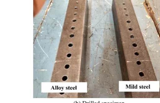
The drilling operation was performed on Alloy steel and mild steel rectangular shaped bar of cross section 300 x 50 x 50 mm as
shown in Fig. 2. The 10 mm diameter High-Speed Steel (HSS) drill bits (JIS-SKD61) as shown in Figs.1(a) and (b). The two
conditions were to be followed (i.e) wet and dry cutting for the drilling operation. The coolant oil used for the machining
process is called wet conditioned machining and when not using the coolant means its dry conditioned drilling.
(a) Coated drill bits (b) Drilled specimen
Table 1 Machining conditions of the drilling operation
Sl.No Machining conditions
1 Condition Wet, Dry
2 Speed 500 rpm, 1000 rpm
3 Feed rate 0.2 mm/rev (Constant)
4 Drill Tool Material ϕ10mm HSS drill bit
5 Coatings & Thickness Pertura & Latuma & t= 4μm Work material EN8 Alloy steel, Mild Steel bar
Table 2 Composition of EN 8 Alloy Steel
Material (EN8/AISI1040) C Mn P S Si Fe
Percentage (%) 0.36-0.44 0.60-1.00 0.05 0.005 0.10-0.40 Remains
Table 3 Chemical composition of Mild Steel
Material (MS/AISI1018) C Cu Mn P Si S Fe
Percentage (%) 0.25-0.29 0.20 1.03 0.04 0.28 0.05 98.0
The new tool coatings were introduced over the drill bits called as Latuma and Pertura. This well bonded Physical Vapour
Deposition method of coatings was deposited over the tool cutting profiles with the thickness of 4μm were performed in
Oerlikon Balzers coating India Pvt. Ltd. The Pertura and Latuma coating are name wise under the brands of PVD coating
which is developed over the tools and the components. The Latuma coating is the newest source of technology which contains
a high amount of aluminum with excellent oxidation resistance and hot hardness. It is having excellent resistance of crater wear
and also used for balancing the residual stress and coating hardness. Its productivity is good with high variables of machining
conditions. It is well suited for the drilling with carbide and HSS drills. Pertura is a Nano-layer structure promises the best
balancing of residual stress, hardness, and fracture toughness and thus dependably stops crack propagation. This allows higher
cutting speeds than with other coatings as well as protracted tool life. It is used for deep hole drilling by using minimum
quantity lubrication. Latuma and Pertura coating have been applied on the surface of the drilling tools with the standard coating
thickness within the ranges of 3-6 μm for the 10 mm diameter High-speed Steel (HSS) drilling tools which were maintained
and performed in Oerlikon Balzers coating India Pvt. Ltd. The drilling operation was performed on the specimen with the low
and high cutting speed of 500 rpm and 1000 rpm at constant feed rate as 0.2 mm/rev is mentioned in Table 1. The chemical
composition of EN 8 Alloy steel and Mild steel are mentioned here below in Tables 2 and 3. The percentage of composition
showed clearly the Manganese and Silicon particulates are involved more in both MS steel and alloy steels. The carbon
percentage is low in mild steel and high in alloy steel based on its density and volume contribution. The machinability was
good in both alloy and mild steel components. Here in this work, the surface roughness and tool wear have to be calculated and
compared with the predictive values of dynamic simulation results.
3.
Experimental Methods
The experiments were carried out on a Universal Radial drilling machine TUV-NABCB-QM002 made from siddhapua
enterprise. By using coated drill tools, the through all holes were performed with the uniform gap of 20 mm in the specimens as
shown in Figs. 2(a), (b) and (c). The uniform feed rate is maintained for all the experiments. The chip formation is good and it
is in the form of continuous chips without any damages.
The results of experimentation were evaluated after drilling in terms of the following measured machining performance:
surface roughness (Ra), burr height (h). The surface roughness of drilled holes was measured by using a Mitutoyo SJ-201
surface roughness tester as shown below in Fig. 3. The instrument was set to a required length and the numbers of specimens
were measured. Four directional measurements of surface roughness were taken perpendicular and parallel to the whole
(a) Universal Radial drilling machine
(b) Drilling without coolants (c) Drilling with coolants
Fig. 2 Drilling operation on Mild Steel and Alloy steel with coated drill bits
The surface roughness values given in this work are the mathematical average of four measurements taken from inside the
same hole surface. The optical profile projector was used for the burr height measurements for some delaminated holes. The
optical systems used in this projector used to produce the fringe patterns of the hole burr outline surface. The dark fringes were
identified and denoted the height of the burrs in the edges of the drilled holes.
Fig. 3 Surface roughness measurement on drilled holes by Mitutoyo SJ-201
The tool wear was identified optically using a tool maker’s microscope. The tip of the drill bits wears out mildly due to the
dry cutting without using coolant. This wear length was measured by using the micrometer provided in the X and Y axis of the
tool maker’s microscope. Various tip tool wear images were captured and showed in Figs. 7(a) and(b). Also here in surface
roughness and machining time from the main effects plot at Figs. 4(a) and (c), the machining conditions either wet or dry and
the tool coatings are the primary and secondary influencing factors on surface roughness. The minimum value is the better
option from the surface roughness responses were well predicted the dominant factors for the betterment of surface quality.
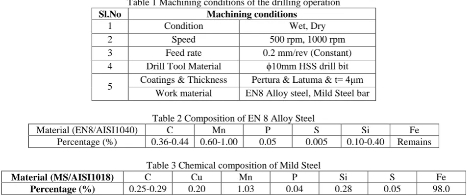
(a) The main effects plot for means of machining time (b) Residual vs Fits for machining time
(c) The main effects plot for means of surface roughness (d) Residual vs Fits for surface roughness
Fig. 4 Means and normal probability chart of machining time (minutes) and surface roughness (μm)
4.
Results and Discussion
After the completion of drilling on mild steel and alloy steel by using coated drill bits, the required output responses were
analyzed and measured the surface roughness and machining time. The main effects plots were identified from the
optimization techniques. The fits verses residual has been plotted based on the array formation in Taguchi’s method. The four
variable material, machining condition, rotational speeds, and the coating types were considered for finding the mean values of
the machining time and surface roughness. The most dominant parameters have easily identified these observations from the
Figs. 4(a), (b), (c) and (d).
Here the machining time saved due to the rotational speed and the tool coating as the foremost parameter. Especially the
Latuma coated drill bit performed well at the machining time at the higher rotational speed of 1000 RPM. Speed and tool
coating are the dominant factors in machining time were identified. The variables are lying nearby the boundary level and
evenly spread over in residual response by the machining time in the normal probability chart. Also here in surface roughness,
from the main effects plot in Fig. 4(c),the machining conditions and the tool coatings are the primary, and secondary
influencing factors on surface roughness. The minimum value is the better option from the surface roughness responses were
well predicted the dominant factors for the betterment of surface quality. The responses were spread over the residual v.s. fits
chart.
In this experiment, only two types of tool coatings were compared for the purpose of identifying the performance during
drilling of different hardness materials like Alloy steel and Mild steel. So we have conducted the experiments based on the two
variations of tool materials, speed, condition, and coating types. It is enough for the findings through L8 orthogonal array
4.1. Prediction of drilling performance
The drilling dynamic performance was accomplished by using Deform 3D dynamic simulator tool. Some predicted values
of stresses and temperatures for the above-mentioned machining conditions by using coated drill bits. Simulated results from
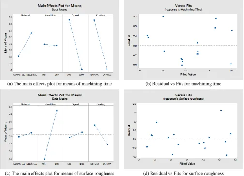
Deform 3D were utilized for the confirmation of the experimental readings of stresses and displacements. The mesh generation
was done on both the drilling tool and the specimen in the preprocessor stage machining. All the required fields of input
parameters were entered in the preliminary steps of machining simulation of Deform platform.
(a) Tool mesh generation
(b) Specimen mesh generation (c) Positioned view of drilling before the simulation
Fig. 5 Tool and workpiece mesh generation in deform 3D simulator in drilling machining
The tool mesh generated by 10697 elements and 2830 nodes and for the workpiece mesh size of 13590 elements and 3161
nodes. The boundary conditions were applied to the workpiece as fixed and the drilling tool is rotated about the Z axis as shown
in Fig. 5(c). The material properties were identified as AISI 1013 from the material library. The simulation controls are
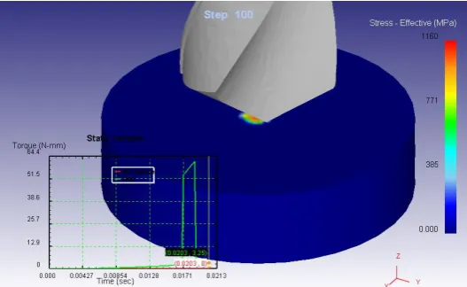
specified as a number of simulation steps and increments for the required drill depth of 5 mm. Higher stresses were acted in
between tool and workpiece due to the interaction effects. This was predicted thorough Deform 3D simulator as mentioned in
Figs. 6(a), (b), (c) and (d). Based on these predicted values wherever effective stress becomes more, the surface roughness will
get poor outcomes. Instead of using uncoated inserts, the coated inserts help to improve the surface properties and machining
time in a very effective manner.
The simulation results showed the effective stress of the tool work interaction and the temperature of the cutting profiles
of both alloy and mild steel drilling operation. These predicted values of σeff and T clearly stated that wherever effective stress
is more, the surface roughness become less in the drilled profiles. Here the drilling of alloy steel gives the surface roughness of
0.841 μm is more than the Ra of mild steel of 0.734 μm at the same rotational speeds of 500 rpm. The temperature distribution
also becomes minimum as 30.7°C during the wet conditioned drilling of mild steel.
Consecutive through all holes were drilled along the surface of both alloy and mild steels with a uniform gap maintained
between each hole. The fewer roughness values that mean good surface finish which had happened during the wet conditioned
machining, especially with Pertura, coated drilling tool achieved a minimum surface roughness of 0.734 μm at minimum speed
(a) Effective stress prediction (Pertura coated tool)
(b) Temperature prediction (Pertura coated tool)
(c) Effective stress prediction (Latuma coated tool)
(d) Temperature prediction (Latuma coated tool)
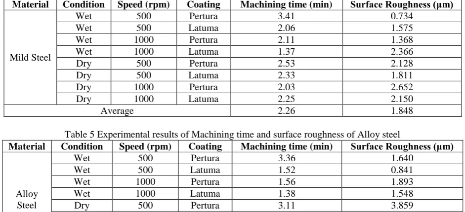
Table 4 Experimental results of Machining time and Surface roughness of Mild steel
Material Condition Speed (rpm) Coating Machining time (min) Surface Roughness (μm)
Mild Steel
Wet 500 Pertura 3.41 0.734
Wet 500 Latuma 2.06 1.575
Wet 1000 Pertura 2.11 1.368
Wet 1000 Latuma 1.37 2.366
Dry 500 Pertura 2.53 2.128
Dry 500 Latuma 2.33 1.811
Dry 1000 Pertura 2.03 2.652
Dry 1000 Latuma 2.25 2.150
Average 2.26 1.848
Table 5 Experimental results of Machining time and surface roughness of Alloy steel
Material Condition Speed (rpm) Coating Machining time (min) Surface Roughness (μm)
Alloy Steel
Wet 500 Pertura 3.36 1.640
Wet 500 Latuma 1.52 0.841
Wet 1000 Pertura 1.56 1.893
Wet 1000 Latuma 1.38 1.548
Dry 500 Pertura 3.11 3.859
Dry 500 Latuma 1.40 1.713
Dry 1000 Pertura 1.56 1.369
Dry 1000 Latuma 1.41 1.498
Average 1.91 1.795
Latuma coated drills is not good for dry conditioned machining on mild steel as the specimen. Similarly, for the drilling of
alloy steel, good surface finishes 0.841 μm was obtained during wet conditioned machining with Latuma coated drill bits. The
surface roughness of the fluted area in the coated tooltips were recorded around 0182 μm to 0.324 μm. Here also the surface
quality was achieved well at lower speeds. The machining condition and the rotational speeds are the major dominant factor
here for surface roughness which was identified from Figs. 4(a) and (c). Comparatively the uncoated drill bits were verified
with the coated HSS drilling tools that they were given the higher value of surface roughness ranges from 2.868 μm to 3.417
μm for the drilled holes of both alloy and mild steel. Thus, the hole inner surface quality becomes poor when it will be compared with the holes drilled by the coated tools.
4.2. Effect of coating on surface roughness
The drilling operation was performed by the Pertura and Latuma coated tools at different cutting conditions. The results
revealed that the less machining time was obtained for the drilling of an alloy steel material at higher rotational speeds. Latuma
coating on drill bits plays an important role in the saving of machining time by the smooth interaction of tool and the specimen.
The surface roughness values are measured by using Mitutoyo SJ-201 tester and mentioned in Tables 4 and 5. Consecutive
through all holes were drilled along the surface of both alloy and mild steels with a uniform gap maintained between each hole.
The fewer roughness values that mean good surface finish which had happened during the wet conditioned machining,
especially with Pertura, coated drilling tool achieved a minimum surface roughness of 0.734 μm at minimum speed and 1.368 μm at both low and high rotational speeds for the Mild steel specimen. Latuma coated drills is not good for dry conditioned
machining on mild steel as the specimen. Similarly, for the drilling of alloy steel, good surface finishes 0.841 μm was obtained
during wet conditioned machining with Latuma coated drill bits. Here also the surface quality was achieved well at lower
speeds. The machining condition and the rotational speeds are the major dominant factor here for surface roughness which was
identified from Figs. 4 (c) and (d).
4.3. Effect of coating on tool wear
After the dry and wet conditioned drilling was performed on the alloy and mild steel specimens, the tool wear was
captured on the different coated High-speed Steel (HSS) drill bits by using the tool maker’s microscope. The micrometer X and
(a) Wear length of Latuma coated drill bit (b)Wear length of Pertura coated drill bit
Fig. 7 The span of tool wear images of coated high-speed steel drill bits by tool maker’s microscope
The Latuma and Pertura PVD coatings were deposited warmly along the entire flute length of the drill bits. The margin
wear was identified below the chisel edge of the Pertura coated drill bits. It was measured vertically below the lip of the drill bit
by using micrometer read markings in the tool maker’s microscope. The wearing length of 5.36 mm was observed along the
rake face of the Pertura coated drill bit as margin wear. Similarly, the tiny margin wear on the rake face of the Latuma coated
drill bit was measured as 0.96 mm. The comparison was made among these two coated drilling tools, the coated drill bits
achieved less in tool wear when it was involved wet and dry cutting conditions. There were no such wear markings were
identified on Latuma coated drill bits. It was measured vertically below the lip of the drill bit by using micrometer read
markings in the tool maker’s microscope. The wearing length of 5.36 mm was observed along the rake face of the Pertura
coated drill bit as margin wear. Similarly, the tiny margin wear on the rake face of the Latuma coated drill bit was measured as
0.96 mm. The comparison was made among these two coated drilling tools, the coated drill bits achieved less in tool wear when
it was involved in wet and dry cutting conditions. There were no such wear markings were identified on Latuma coated drill
bits.
4.4. Interpretation of results
The surface roughness becomes good in alloy steel because it is having naturally 0.36-0.44% of carbon is relatively high
and also the silicon participation is maximum up to 0.4% compared with the mild steel. This will lead to achieving less surface
roughness value. At the same time, coated drill bits were deposited by the PVD method with the additive of Al and Cr
combined form particulates. So the chemical interaction and temperature distribution were occurred in between the coated tool
and the inner surface of the hole. The slight deposition of Al and Cr particles from Latuma and Pertura coated drill bits leads to
change the surface integrity with respect to the machining conditions. Less tool wear was created from the Latuma coated drill
bits compare with the Pertura coated drill bit. Margin wear marks were identified in the flute rake face of the Pertura coated
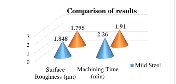
drill bit as shown in Fig.7(b). The comparison was made accordingly among the surface roughness of the specimen and the
tool wear level of the drill bits has been demonstrated by the Fig. 8.
Fig. 8 Comparison of Surface roughness and Machining time 0
1 2 3
Surface Roughness (μm)
Machining Time (min)
1.848 2.26
1.795 1.91
Comparison of results
5.
Conclusions
In this work, the surface quality was achieved with the contribution of Latuma and Pertura coated drill bits effectively.
Especially the holes were made on both alloy and mild steel during the wet conditioned drilling operation was very successful.
The surface roughness decreased at a low rotational speed of 500 rpm in the drilling of mild steel with Pertura coating.
Simultaneously the Latuma coated tool achieved well during the wet machining of ally steel material. Here the rotational speed
and the tool coatings are the more dominant thing on surface roughness and machining time. The optimization results can be
made the things very easy to identify the influencing elements through the SN ratio and main effects plots. The tool wear was
analyzed on those Latuma and Pertura coated drill bits. Very few wear images were obtained on Latuma coated compare with
the Pertura coated drill bits. The wear span of Latuma coated drill tip edge is very small rather than the Pertura coated one. The
dynamic simulation helps to predict and adopt a strong understanding of the stresses and temperatures of machining
interactions.
Conflicts of Interest
The authors declare no conflict of interest.
References
[1] J. Pradeep Kumar and P. Packiaraj, “Effect of drilling parameters on surface roughness, tool wear, material removal rate, and hole diameter error in drilling of ohns,” International Journal of Advanced Engineering Research and Studies, vol. 1, no. 3, pp. 150-154, June 2012.
[2] B. V. Kavada, A. B. Pandey, M.V. Tadavi, and H. C. Jakharia, “A review paper on effects of drilling on glass fiber reinforced plastic,” ICIAME 2014, Procedia Technology, vol. 14, pp. 457-464, August 2014.
[3] M. A. J. Bosco, K. Palanikumar, B. Durga Prasad, and A. Velayudham, “Influence of machining parameters on
delamination in drilling of GFRP- armour steel sandwich composites,” NUiCONE 2012, Procedia Engineering, vol. 51, pp. 758-763, January 2013.
[4] E. Bahce and C. Ozel, “Experimental investigation of the effect of machining parameters on the surface roughness and the formation of built up edge (BUE) in the Drilling of Al 5005,” Tribology in Engineering, Hasim Pihtili, IntechOpen, Chapter 2, pp. 15-28, May 2013.
[5] Cicek A. Kıvak, T. Samtas, G. Adem Cicek, Turgay Kıvak, and Gurcan Samtas, “Application of taguchi method for surface roughness and roundness error in drilling of AISI 316 stainless steel,” Journal of Mechanical Engineering, vol. 58, no. 3, pp. 165-174, January 2012.
[6] N. S. Mohan and S. M. Kulkarni, “Influence of drilling parameters on torque during drilling of GFRP composites using response surface methodology,” The 2nd International Joint Conference on Science and Technology (IJCST) pp. 1-7, September 2017.
[7] A. A. Thakre, “Modelling of burr size in drilling of aluminium silicon carbide composites using response surface methodology,” An International Journal of Engineering Science and Technology, vol. 19, pp. 1199-1205, March 2016.. [8] X. Chen, L. Xie, X. Nan, J. Tian, and W. Zhao, “Experimental study of small hole drilling characteristics of SiCp/Al
composites,” Procedia CIRP, vol. 46, March 2016 pp. 319-322.
[9] Puneeth. V and Smitha. B, “Studies on tool life and cutting forces for drilling operation using uncoated and coated HSS tool,” International Research Journal of Engineering and Technology (IRJET), vol. 4, no. 6, pp. 1949-1954, June 2017. [10] B. Pradeep Kumar, Dr. N. V. N. Indra Kiran, and S. Phani Kumar. “Effect of cutting parameters in drilling of EN8
(080M40) carbon steel to obtain maximum MRR and minimum temperature by using RSM (under dry condition)” International Journal of Engineering and Management, vol. 7, no. 2, pp. 533-539, April 2017.
[11] R. Sreenivasulu and C. S. Rao, “Effect of drilling parameters on thrust force and torque during drilling of aluminium 6061 alloy based on taguchi design of experiments,” Journal of Mechanical Engineering, no. 46, pp. 41-48, December 2016. [12] D. Shetty S, N. Shetty, A. Rajat, G. Shetty, and P. Patil, “Characterization of machining parameters on thrust force and
surface roughness in drilling of 40-60 Wt. % BD CFRP composite,” International Journal of Applied Engineering Research, vol. 12, no. 16, pp. 5570-5577, September 2017.
[14] D. Arola and C.L. Williams, “Estimating the fatigue stress concentration factor of machined surfaces,” International Journal of Fatigue, vol. 24, pp. 923-930, September 2002.
[15] J. M. Dasch, C. C. Ang, C. A. Wong, Y. T. Cheng, A. M. Weiner, L. C. Lev, and E. Konca, “A comparison of five categories of carbon-based tool coatings for dry drilling of aluminum,” Surface and Coatings Technology, vol. 200, pp. 2970-2977, February 2006.
[16] X. Wang, X. Shen, C. Zeng, and F. Sun, “Combined influences of tool shape and as-deposited diamond film on cutting performance of drills for CFRP machining,” Surface and Coatings Technology, vol. 347, pp. 390-397, May 2018. [17] D. U. Braga, A. E. Diniz, G. W. A. Miranda, and N. L. Coppini, “Using a minimum quantity of lubricant (MQL) and a
diamond coated tool in the drilling of aluminum-silicon alloys,” Journal of Materials Processing Technology, vol. 122, pp. 127-138, March 2002.
Copyright© by the authors. Licensee TAETI, Taiwan. This article is an open access article distributed under the terms and conditions of the Creative Commons Attribution (CC BY-NC) license