Copyright © 2015 IJECCE, All right reserved 255
Improved Performance of a Wind Energy Conversion
Chain Driven by an Asynchronous Generator
Doubly-Fed and Using a « R-L » Filter
Aïcha Wahabi
Assistant professor, The superior school of technology (EST)
email: [email protected]
Abdelhadi EL Moudden
Empowered Professor, The National School of Electricity and Mechanics (ENSEM)
email: [email protected]
Fatima Ezzahra Bounifli
Doctoral Student, The National School of Electricity and Mechanics (ENSEM)
email: [email protected]
Abdelali Aarib
Doctoral Student, The National School of Electricity and Mechanics (ENSEM)
email: [email protected]
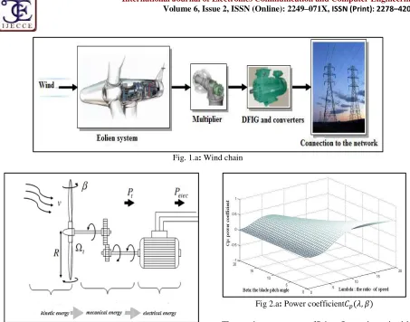
Abstract: The objective of this work is the study of wind energy conversion in its entirety in order to optimize the power output, improve the quality of the energy supplied and thus make the operating point on high MPTT. For this, we are interested in modeling and simulation of a wind turbine associated with a speed multiplier, an asynchronous generator doubly-fed (DFIG) and power converters interconnected via a DC bus. Then we have introduced a filter to improve the performance of the chain. We conducted the simulation and modeling of the indirect control of the DFIG. The technique adopted the algorithm is developed in Matlab/Simulink/SimPowerSystems. Simulation results are presented and analyzed at the end of this work.
Keywords: Converter, DC Bus, DFIG, MLI, Modeling, Matlab / Simulink, Turbine, «R-L» Filter, Wind Chain, Wind Turbine.
I.
I
NTRODUCTIONThe development and use of renewable energy have experienced strong growth in recent years. These sources of energy, wind generators have a special place.
Interest in the doubly-fed induction generator (DFIG) is increasing especially in the field of renewable energy. Indeed, in the wind energy area, the DFIG has many advantages: The converter linked to the rotor armature is sized to a third of the rated power of the rotor, the losses in the semiconductor their costs are thus reduced. Indeed, currently the most wind turbines are equipped with DFIG This is due to several advantages: The power variable speed generation (± 30% around the synchronous speed) which allows operation over a wide range wind speeds, and derive the maximum possible power for each wind speed: This is the principle of maximum Power Point Tracking (MPPT). The use of DFIG allows the decoupled control of active and reactive power, reducing losses, mechanical stress and improving the acoustic noise and the quality of the power produced. But, the DFIG is subject to many constraints, such as the effects of parametric uncertainties (due to the heating, saturation...) and disruption of the variation of wind speed, which could divert the system from its optimal operation. This is why
the check should be concerned about the robustness and performance.
The development of power electronics has had a major impact on the industrial world in the last decades. This rise occurred with the arrival on the market of electronic power components such as thyristors, triacs, GTO, IGBT or high power transistors. These components have enabled the development of high power static converters which allow conversion of electrical power from some form to another form. These converters provide substantial progress in industrial processes. In this article, we begin by modelling and simulation blocks the wind turbine and asynchronous generator and DC bus converters. We will then analyse and compare the performance of the chain before and after the addition of an "RL" filter through simulations in Matlab / Simulink / SimPowerSystems.
II.
D
ESCRIPTION OF AS
YSTEM OFW
INDE
NERGYC
ONVERSIOND
RIVEN BY THE“DFIG”
International Journal of Electronics Communication and Computer
Copyright © 201 Fig. 1.b:Schematic diagram of wind chain
III.
M
ODELING ANDS
IMULATION OF THET
URBINEA. Principle of modeling
By applying the theory of the momentum and the Bernoulli theorem, we can determine the incident power (the theoretical power), due to the wind [5][6]
. .
:The surface swept by the blades of the turbine
: The density of air (ρ = 1225 kg / m3 at atmospheric pressure);
: Wind speed [m /s].
In a turbine, the power extracted from provided on the rotor of the turbine is lower than the incident power.
. . , .
, : is the power coefficient which expresses the efficiency of the turbine, it depends on the ratio
represents the ratio of the turbine speed at the end of the blades and the wind speed, and the orientation angle
. !
"
International Journal of Electronics Communication and Computer
Volume 6, Issue 2, ISSN (Online): 2249–071X,
Copyright © 2015 IJECCE, All right reserved 256
Fig. 1.a: Wind chain
of wind chain
IMULATION OF THE
By applying the theory of the momentum and the Bernoulli theorem, we can determine the incident power (the theoretical power), due to the wind [5][6]:
(1)
The surface swept by the blades of the turbine [m²]; = 1225 kg / m3 at atmospheric
In a turbine, the power extracted from provided on the the incident power.
(2)
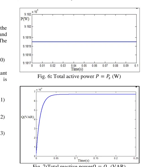
is the power coefficient which expresses the efficiency of the turbine, it depends on the ratio, this ratio represents the ratio of the turbine speed at the end of the blades and the wind speed, and the orientation angle .
(3)
Fig 2.a: Power coefficient
The maximum power coefficient Albert Betz (1920) as follows:
#$ , %&' 0,593
This coefficient depends on the constitution of the turbine, for a wind medium power we have:
, , . -,../ ,0. / ,
Fig. 2.b: 1
Note that although the path checks the based on the expression (6):
#$ , %&' 0,593
International Journal of Electronics Communication and Computer Engineering
071X, ISSN (Print): 2278–4209
Power coefficient,
The maximum power coefficient was determined by
(4)
This coefficient depends on the constitution of the turbine, for a wind medium power we have:
,23 . 456.7 ,%. (5)
for 0°
Note that although the path checks the Betz limit is
Copyright © 201 Also, we can say that this turbine will present its maximum efficiency for a speed ratio
order of 23 since in general, is maximal for
is the torque on the slow axis at the turbine
NOP!! . . , . 0. !
The total inertia j consists of the inertia of the turbine reduced the fast axis and the inertia of the generator
Fig.3: Schematic diagram of the turbine
C. Simulation Results:
Fig.4: Mechanical torque supplied by the turbine
Weused the "Stall control" technique is a passive technique that allows a natural aerodynamic stall. We obtained a constant torque Output of the
simulated model is well suited to our conversion chain studied. Optimal Lambda Ω RS4 T Wind
UW4VU
U
1 2 . . S
Copyright © 2015 IJECCE, All right reserved we can say that this turbine will present its
maximum efficiency for a speed ratio [1][2],of the
is maximal for 0 °
is the torque on the slow axis at the turbine :
(7)
The total inertia j consists of the inertia of the turbine [ reduced the fast axis and the inertia of the generator[\:
[ ]!
^_7 [\
The fundamental equation of dynamics can be written
[ `Oa
b / #/ 1W
B. Block Diagrams of the Turbine
In order to subtract the maximum power of the incident energy, must continuously adjust
the turbine to the wind:
Schematic diagram of the turbine with Proportional-Integral (PI)controllers
Mechanical torque supplied by the turbine
Weused the "Stall control" technique is a passive technique that allows a natural aerodynamic stall. We utput of the turbine, so the simulated model is well suited to our conversion chain
IV.
M
ODELING ANDS
IMULATION OFA
SYNCHRONOUSG
A. Principle of modeling
The asynchronous generator double
modeled in the cue Park by the following equations [5]:
c Tcdc 7 ∅c/ fc∅gc
gc Tcdgc 7 ∅gc/ fc∅c
h Thdh 7 ∅h/ fh∅gh
gc Thdgh 7 ∅gh/ fh∅h
With: fh fc/ S. W
i j
kllc mcdc7 ndh
gc mcdgc7 ndgh
lh mhdh7 ndc
lgh mhdgh7 n dgc
o
Cn Ωqé,s41
Ωns41
ΩUs41
ΩU CS CU Cq C4q PI + - + _ _ 1 t + _ _ 1 [u 7 1
PI
1 t T. Ωt 1 tS, . 3.1 W U
(8)
The fundamental equation of dynamics can be written:
Wb (9)
urbine
In order to subtract the maximum power of the incident energy, must continuously adjust the speed of rotation of
controllers
IMULATION OF THE
G
ENERATORThe asynchronous generator double-fed (DFIG) is by the following equations [4]
gc (10)
c (11)
gh (12)
h (13)
(14)
(15), (16), (17), (18)
Cn Ωqé, Ωqé,
International Journal of Electronics Communication and Computer
Copyright © 201 Also: mu vu – nu and ms vs – n
xyz, {yz:Voltage and current stator along the axis d
x|z, {|z:Voltage and current stator along the axis q
xy},{y}: Voltage and current rotor along the axis d
x|},{|}:Voltage and current rotor along the axis q
∅yz, ∅y} :Stator and rotor flow along the axis d
∅|z, ∅|}:Stator and rotor flow along the axis q
~z, ~} :Stator and rotor cyclic inductance
z, } :Stator and rotor inductance, respectively
z: Mutual inductance between two stator phases
}: Mutual inductance between two rotor phases
: Magnetizing inductance
:Rotation speed of the machine
z, } : Stator and rotor pulsation, respectively
z, } : Stator and rotor resistance per phase, respectively
z, z :Active and reactive statorpower
:Electromagnetic torque
:Number of polepairs
To adequately control the electricity production of the wind, we will achieve independent control of active and reactive powers c and c stator [2] [3] [4] [5]
reference () is oriented so that:
lc lcandlgc 0
Assuming that the stator flux lc is
electric network) and ignoring the stator resistance is obtained forc, cand#:
c /cbdgh
c / cbdh7 _
# /Sb ∅ cdgh
We obtain this schematic diagram:
2) Variation of voltages $c, c and
International Journal of Electronics Communication and Computer
Volume 6, Issue 2, ISSN (Online): 2249–071X,
Copyright © 2015 IJECCE, All right reserved 258
ns (19)
oltage and current stator along the axis d oltage and current stator along the axis q
otor along the axis d along the axis q tator and rotor flow along the axis d tator and rotor flow along the axis q
nductance, respectively , respectively Mutual inductance between two stator phases
ctance between two rotor phases
, respectively
tor resistance per phase, respectively power
To adequately control the electricity production of the wind, we will achieve independent control of active and [2] [3] [4] [5] [6]. The
(20)
is constant (constant electric network) and ignoring the stator resistance is
(21)
(22)
(23)
Fig. 5: Schematic diagram of the DFIG
B. Simulation results
1) Active and reactive power
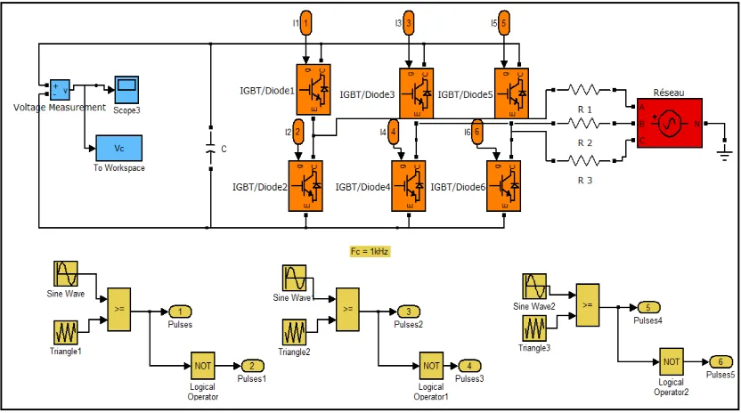
Fig. 6: Total active power
Fig. 7:Total reactive power
and c
Fig. 8:Stator voltages u u ,u
International Journal of Electronics Communication and Computer Engineering
071X, ISSN (Print): 2278–4209
Schematic diagram of the DFIG
Total active power c (W)
Copyright © 2015 IJECCE, All right reserved 259
C. Comments and Discussion
Powers Granted by the asynchronous generatorare equal
to: ' 9181.9 and ' 6700 T (Fig.6 and
Fig.7), these values are correct indeed. Note that the wind channel provides a considerable active power:The minus sign indicates that this course is a power output.
The terminal voltage of the stator of the generator is sinusoidal, effective value close to 380V and '
0,02uperiod, (Fig.8) that is to say, 50Hz frequency. We
can say that the machine operates in its optimal conditions
(RvU4 380and TU4 s44, 50 ).
V.
C
ONVERTERS AND THEC
ONTINUOUSB
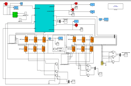
US A. PrincipleFig. 9:Schematic diagram of converters and DC bus
B. Pulse width Modulation (PWM)
The modeling of PWM rectifier[7], is represented by the following figure:
International Journal of Electronics Communication and Computer
Copyright © 201 C. Result of the simulation
We see that we get an impulsions train that is well suited to our system, in fact we get every moment tension "most positive", that is to say, the highest in absolute value.
Fig. 12:
International Journal of Electronics Communication and Computer
Volume 6, Issue 2, ISSN (Online): 2249–071X,
Copyright © 2015 IJECCE, All right reserved 260
Fig. 11:I GBT command signals
We see that we get an impulsions train that is well suited to our system, in fact we get every moment tension "most positive", that is to say, the highest in absolute
VI.
M
ODELING ANDS
C
OMPLETEC
HAINC
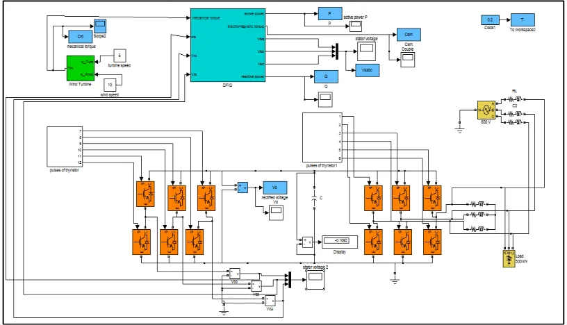
After studying each element separately, now, we interest us to model and simulate the system in its entirety
A. Without filter
Diagram of the full open loop system without filter
International Journal of Electronics Communication and Computer Engineering
071X, ISSN (Print): 2278–4209
S
IMULATION OFC
ONVERSIONCopyright © 201 B. With an “R-L” filter
Fig. 13: Diagram of the full open loop system with an “R
C. Simulation results
Fig. 14:The continuous bus v
Fig. 15: The continuous bus voltage after adding the filter Copyright © 2015 IJECCE, All right reserved
Diagram of the full open loop system with an “R-L” filter
The continuous bus voltage before adding the filter - meanV¡' 300
The continuous bus voltage after adding the filter- mean V¡' 600
300V
International Journal of Electronics Communication and Computer Engineering
Volume 6, Issue 2, ISSN (Online): 2249–071X, ISSN (Print): 2278–4209
Copyright © 2015 IJECCE, All right reserved 262
D. Comments and discussions
When we gathered all the elements of the chain, we have made improvements to different parts of the model for that they are compatible.
We note that the terminal voltage of continuous bus is between 0 and 700V DC and adding filters actually improves the quality of this tension and has increased its average value (see Fig.13 and Fig.14).
Reactive power conveyed by the DC bus is equal to: Without filter ,' 14,2 £T;
After adding filter, ' 55, 1 £T.
We find that the second channel with filter will perform better because it is this power that will be transmitted to the inverter to power the load or injected to the network.
VII.
C
ONCLUSION ANDO
UTLOOKFrom the results given above, we can conclude that the chain is correctly modelled and simulated in its entirety. The filter addition clearly improves the efficiency of the chain, by increasing the average value of the DC bus voltage and therefore the power absorbed.
The continuation of our work is to insert the voltage control loop and power in order to minimize parasitic fluctuations observed in the trace of the voltage across the capacitor.
VIII.
S
IMULATIONP
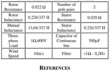
ARAMETERTable 1: Characteristics of the wind chain Rotor
Resistance 0.022 Ω
Number of
pole pairs 2 Rotor
Inductance 0.226/337 H
Stator
Resistance 0.029 Ω Mutual
Inductance 13,04/337 H
Stator
Inductance 0.226/337 H
Three-phase Load
1Ω,600V
Capacitor of Continuous
bus
500µF
Wind
Speed 10m/s Filter «1Ω - 0,2H»
R
EFERENCES[1] A.El Moudden, A.Wahabi, A.Sandali, F.E.Bounifli.“Control and Optimization of the Energy Produced by a Chain of Wind Energy Conversion Controlled by a Double-fed Asynchronous Generator”. June-July 2014 Current Trends in Technology and Sciences (CTTS).
[2] A. El Moudden, A.Aarib, A. Wahabi, F. E. Bounifli.“Command of the active and reactive stator powers of the doubly-fed induction generator used in wind energy”. International Journal of Emerging Technology and Advanced Engineering (IJETAE),Website:
www.ijetae.com(ISSN 2250-2459, ISO 9001:2008 Certified
Journal, Volume 4, Issue 10, October 2014).
[3] A. El Moudden, A.Wahabi, A.Sandali, F.E.Bounifli, “Modelling and simulation of a double-fed asynchronous generator for control of wind energy”, International Congress of Thermal, Agadir, Maroc, April 2014.
[4] A.Boyette controlling a doubly-fed asynchronous generator with the storage system. PhD University Poincaré, Nancy, 2006.
[5] K. Belmokhtar, ML Doumbia, K. Agbossou, modelling and control of a wind energy system based asynchronous machine dual power to supply power to the electricity grid, Journal of Scientific Research vol. 2 (2010).
[6] F. Kendouli, K. Nabti, K. Abed et H. Benalla, Modelling and simulation of a double-fed asynchronous,review of renewable energy volume 14 March 2011.
[7] S. Khojet El Khil, Vector control of a doubly fed induction machine (DFIG) / Optimization losses in the converters, 2006.
A
UTHOR'
SP
ROFILESPr. Wahabi Aicha
I am, an assistant professor at the superior school of technology (EST) in Casablanca, Morocco since 1991.From 2012 to the present, I’m a member of Laboratory of Computing, Systems and Renewable Energy (LISER)-Team Analysis and Command of Electrical Energy Systems(ACSEE). I wish to inform you that I'm preparing my habilitation in energy renewable more precisely wind energy turbine, in the National School of Electricity and Mechanic (ENSEM). I completed the diploma of superior depth studies in 2000 in the National School of Electricity and Mechanic (ENSEM) Casablanca, Morocco; I am also an electromechanical engineer of the National School of Mineral Industry (ENIM) in Rabat, Morocco (in 1990). I have already presented three papers in Morocco on wind energy during the years 2013 and 2014.
Pr. Dr. EL Moudden Abdelhadi Doctor of Science from The National Polytechnic Institute of Toulouse (INPT) in 1993 - FRANCE. He is now a professor in the National School of Electricity and Mechanics (ENSEM), University Hassan II Aïn Chock, Casablanca, Morocco. Since 2006, he has been a member of LaboratoryComputing, Systems and Renewable Energies (LISER) - TeamAnalysis and CommandofElectrical EnergySystems(ACSEE).
His research interests include Dynamic Simulations of Electric Machinery, Simulation and Optimization of Renewable Energy Systems. He has presented and published many articles in scientific journals and conferences.
Bounifli Fatima-Ezzahra
I am electrical engineer at OCP Group, Morocco (since 2014). I am also a doctoral student preparing a doctoral thesis in the National School of Electricity and Mechanics (ENSEM), University Hassan II Aïn Chock, Casablanca.TeamAnalysis and CommandofElectrical EnergySystems (ACSEE) - Laboratory of Computing, Systems and Renewable Energy (LISER). On June 2013, I got an engineering diploma specialized in electrical energy in ENSEM. My doctoral thesis is about direct and fuzzy-logic control systems of the double-feed induction generator wind turbine. I’ve submitted three papers in Morocco on wind energy during the years 2014 and 2015.
Aarib Abdelali