Copyright © 2015 IJECCE, All right reserved 72
Performance Improvement of MIMO MC-CDMA
Receiver Using the CORDIC Algorithm
Youness MEHDAOUI
SMBA University Fez, Moroccoemail:[email protected]
Mostafa MRABTI
SMBA University Fez, Moroccoemail:[email protected]
Rachid EL ALAMI
SMBA University Fez, Morocco email:[email protected]Abstract: Industry communications systems without thread has grown tremendous over the last few years, these systems have evolved significantly in terms of services offered. Why the deployment of new communications systems(LANs, mobile radio systems, etc.) requiring transmit rates higher and higher in frequency bands is reduced more important but the traditional systems of transmission for the information which should be issued successively over time were put in competition with new approaches in which the information is transmitted simultaneously, but the speed of the processing time has always been a big problem of digital communication. The main objective of this work is to design an improvement for speed with a better precision in MIMO MC-CDMA broadband receiver for optimal data processing.
This work proposes to focus on the design methodology and experimental implementation of a MIMO MC-CDMA receiver using DSP C64x+, we propose a new architecture of a MIMO MC-CDMA Receiver. The interest of this architecture is an enhancement that allows reducing the processing time data from a MIMO MC-CDMA receiver keeping better performance using the CORDIC operator and the fixed point to increase processing rates.
Keywords: (MIMO MC-CDMA Receiver), CORDIC, FFT, fixed point, time of processing, DSP Processor
I.
I
NTRODUCTIONThe requirement of data transmission through mobile radio interface also increases rapidly [1].The traditional systems of transmission for the information which should be issued successively over time were put in competition with new approaches in which the information is transmitted simultaneously. These new approaches, permit a better exploitation of the propagation channel (OFDM) [2], and can, in the context of multi users access (CDMA), facilitates the extraction of transmission resources [3]. Currently these methods tend to merge MC-CDMA to obtain the best efficiencies possible transmission [2].The MC-CDMA has become one of the attractive candidates for next-generation mobile communications [4].Where the speed of the processing time has always been a big problem of digital communication. In this paper, we present a solution to decrease the time of data processing for a MIMO MC-CDMA receiver. This paper is organized as follows: In section 2, we explain the MIMO MC-CDMA theory and the CORDIC algorithm. The fix-point development is given in section 3. The proposed MIMO MC-CDMA receiver and the results obtained by the implementation of this receiver on C64x+ are presented in section 4, 5 and 6 respectively. We finish this paper by a conclusion (section 7).
In the MIMO channel, consider a scenario where there are Nu users communicating synchronously with a common
base station. Each user station (mobile station) has M
transmit antennas and the base station has N receive antennas [5, 6, 7].
II.
T
HEORYA.
System model
Figure.1 and Figure.2 show the simple model of MIMO-MC-CDMA transmitter and receiver respectively. The transmitter of MIMO-MC-CDMA consists of direct sequence spreader and OFDM modulator. In these schemes the pilot sequence are very important for the performance. After modulating, the data stream is multiplied by a spreading sequence. The length of this spreading code is usually identical to the number of sub carrier. The pilot signals are multiplexed to the data streams, after OFDM modulation the signals are transmitted through multiple antennas.
Fig.1. Simple Model of MIMO MC-CDMA Transmitter
Fig.2. Simple Model of MIMO MC-CDMA Receiver
The received signal is demodulated using Fast Fourier transform (FFT). After OFDM demodulation the user data symbols and pilot symbols are recovered by despreading with corresponding spreading codes. The required transfer function for channel estimation and equalization is recovered from pilot sequence. Finally the original data stream is recovered by dividing the received signal by channel response. At the receiver end, the demodulator process the channel equalized waveform and reduces each waveform to a scalar (or) a vector that represents an estimation of the transmitted data symbol. The detector, which follows the demodulator, decides whether the transmitted bit is a 0 or 1.
Copyright © 2015 IJECCE, All right reserved 73
NT
x
NR MIMO system, the transmitted signal aftermodulation can be expressed as
= ∑�=−∞∞ √� ���∑��=� ∑�=� k � nµ�� − ��� cos ѡ� (1)
where Eb and Ts ar0e the bit energy and symbol duration
respectively, uTs(t) represents a rectangular waveform with
amplitude 1 and pulse duration Ts, bk(i) is the ith transmitted
data bit cn is the spreading code, NT is the transmitting
antenna, ωn= 2πf0+ 2π(n - 1)Δf is the radian frequency of
the nth subcarrier, and the frequency spacing is Δf = 1/Ts.
The received signal r(t) through receiving antenna NR is
given by
= η + ∑�=−∞∞ √� ���∑��=�∑�=� ℎn k� nµ�� − ��� cos ѡ� + ��(2)
Where hn is the subcarrier flat fading gain, φn is the
subcarrier fading phase and η(t) is AWGN with single-sided power spectral density N0. After phase compensation,
the receiver performs amplitude correction using equalizer coefficient. The received signal after FFT is given by
Y � = X � H � + W � , � = , , … , �n− (3)
The received pilot signals Yp(k) is extracted from Y(k) ,
the channel transfer function H(k) can be obtained from the information carried by Hp(k) . With the knowledge of the
channel responses H(k) , The transmitted data samples signal X(k) can be recovered by simply dividing the received signal by channel response
X � =H �Y � (4)
The equalizer co-efficient is expresses as [16] �′= �
��− ��� (5)
Rby is the constructive cross correlation matrix that
contains the ρuk elements of Ryy.
Ryy is the cross correlation matrix of modulated signature
waveform.
B.
CORDIC algorithm
As explained in [8]; The CORDIC algorithm provides an iterative method of performing vector rotations by arbitrary angles using only shifts and adds. The basic equations required to implement CORDIC are:
sin cos i Y 1 i Y sin cos i X 1 i X i X i Y (6)
i 1 c (
tan ) Y ) tan ( cos 1 i X i X i Y os i Y i X (7)If the rotation angles are restricted so that 1 2 tan ethe
multiplication by the tangent term is reduced to simple shift operation, we can be written as:
i 1 (
.2 )Y ) 2 . . ( 1 i X i e i i i e i i d i X i Y K d i Y i X K (8)
i 1
.Z Z i di (9)
where
We can ignore ignore
K
iin the iterative process, it can be noted that:Ki0.6073and 1
i
d if Z
i 0 , 1 otherwisewhich finally provides the following result
0 0 0 0
n 0 0 0 0 n
sin
.
cos
Y
sin
.
cos
X
Z
X
Z
Y
A
Z
Y
Z
X
A
n n
(10) 0 n Z ) 2 + (1 2i
n nA (11)
So to reach an expected angle, a series of iterations are required to be performed and in this design the number of iterations arei8and in every iteration the new values of
y
x
,
andz
depend upon the previous values of the same [8].C. Sine and Cosine Calculation
In the survey paper [8], it is shown that the rotational mode CORDIC operation can simultaneously compute the sine and cosine of the input angle as:
0 0 n 0 0 n sin . Y cos . X Z X A Z X A n n (12)
where the y component of the input vector is setting to zero.
By settingX0 1/An, the rotation produces the un-scaled
sine and cosine of the angle argumentZo. It is worth noting that the hardware complexity of the CORDIC rotator is approximately equivalent to that of a single multiplier with the same word size [9].
III.
T
HEF
IX-P
OINTD
EVELOPMENTThe diagram below illustrates a typical development scenario in use today:
Fig.3. The fix-point development dilemma
The design may initially start with a simulation (i.e. MatLab) of a control algorithm, which typically would be written in floating-point math (C or C++). Existing
methodologies [10, 11] achieve a floating-to-fixed-point transformation leading to an ANSI-C code with integer data types. This algorithm can be easily ported to a floating-point device. However, because of the commercial reality of cost constraints, most likely a 16-bit or 32-bit fixed-point device would be used in many target systems.
The effort and skill involved in converting a floating-point algorithm to function using a 16-bit or 32-bit fixed-point device is quite significant. A great deal of time (many
1 1
2 tan
cos
e
i
Copyright © 2015 IJECCE, All right reserved 74
days or weeks) would be needed for reformatting, scaling and coding the problem. Additionally, the final implementation typically has little resemblance to the original algorithm [12].
For digital signal processors (DSPs), the methodology
aim is to define the optimized fixed point specification
which minimizes the code execution time and leads to sufficient accuracy [13], some experiments [14] can represent up to 30% of the global implementation time.
IV.
P
ROPOSEDMIMO
MC-CDMA
R
ECEIVERFuture wireless communication systems need improvement in spectral efficiency (increased of rate of flow), the following diagram shows the MIMO MC-CDMA receiver using CORDIC fixed point in order to increase the processing rates.
In this work, we are interested to implement a MIMO MC-CDMA receiver using a DSP device.
The following diagram shows MIMO MC-CDMA receiver using CORDIC algorithm and fixed point.
Fig.4. The Architecture of MIMO C-CDMA Receiver using CORDIC into fixed point
In our systems based on the MIMO MC-CDMA method, every sequence is encoded by 16 chips Walsh-Hadamard sequence, and each column of emission matrix is modulated by two IFFT. We propose an MIMO MC-CDMA receiver based on CORDIC algorithm and Fixed Point using a DSP (TMS320C64x+).
We give the parameters in Table 1, and we propose an MIMO MC-CDMA receiver based on CORDIC algorithm and Fixed Point using a DSP (TMS320C64x+).
Table 1: Parameters
Channel Rayleigh fading
Modulation BPSK/16 QAM/64QAM
Antennas 2x2
Equalization/Estimation MMSE/Pilot
FFT size 512
Spreading Codes Walsh-Hadamard Code
V.
I
MPLEMENTATIONA.
Hardware implementation
The algorithms are implemented using DSP Processor Based on 65-nm process technology and 3.0 GHz of total raw DSP processing power with performance of up to
24,000 million instructions per second (MIPS) [or 24,000 16-bit MMACs per cycle], the C6474 device offers cost-effective solutions to high-performance DSP programming challenges with three independent DSP subsystems. The DSP possesses the operational flexibility of high-speed controllers and numerical capability of array processors.
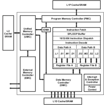
DSP Block Diagram
Fig.5. TMS320C64x+ DSP Block Diagram
The C64x core by performing four 16-bit x 16-bit multiply-accumulates (MACs) every clock cycle. Thus, eight 16-bit x 16-bit MACs can be executed every cycle on the C64x+ core. At a 1.0-GHz rate, this means 8000 16-bit MMACs can occur every second. Moreover, each multiplier on the C64x+ core can compute one bit x 32-bit MAC or four 8-32-bit x 8-32-bit MACs every clock cycle.
The eight functional units (.M1, .L1, .D1, .S1, .M2, .L2, .D2, and .S2) are each capable of executing one instruction every clock cycle. The .M functional units perform all multiply operations. The .S and .L units perform a general set of arithmetic, logical, and branch functions. The .D units primarily load data from memory to the register file and store results from the register file into memory [15].
B.
Software implementation
The simulations were performed using the software Code Composer Studio [16] that uses more effectively the internal hardware of the C64x+. The implementation of the MIMO MC-CDMA receiver based of CORDIC algorithm on a DSP with fixed point. The CORDIC algorithm is used to compute the sine and cosine values which are required to calculate the twiddle factors in FFT for MIMO MC-CDMA Receiver.
The algorithm steps for the software implementation of the MC-CDMA receiver are given below:
a) Remove the Cyclic Prefix from the signal received from channel.
i) Remove the first M samples of the (N + M) samples of the received signal, where M is the cyclic prefix length and N is the actual number of input samples.
Copyright © 2015 IJECCE, All right reserved 75
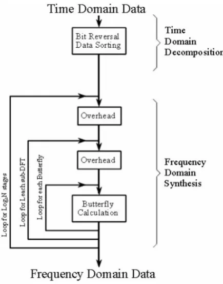
c) Compute the FFT of the samples obtained in step a). i) The flow diagram for FFT Computation is shown in Figure 6.
CORDIC custom instruction is used in the butterfly calculation part of the flow chart.
Fig.6. Flow diagram for FFT Computation
d) Demodulate by FFT a signal obtained in step c) to obtain the spreading signal bits.
e) Despreading of demodulate signal
i) Despreading by Walsh-Hadamard sequence gives the received bits.
VI.
R
ESULTSThe MIMO MC-CDMA receiver is implemented on DSP C64x+ and tested for different input data lengths. The following results are obtained for 64 point FFT length; the clock cycle is equal to 1 GHz.
The three figures 7, 8 and 9 show the number of cycles obtained for the three receivers without CORDIC and with CORDIC.
Fig.7. The number of cycles obtained for the MIMO MC-CDMA receiver
Fig.8. The number of cycles obtained for the OFDM receiver
Fig.9. The number of cycles obtained for the RAKE receiver
Table 2: The cycle’s number and their ratios
MIMO MC-CDMA receiver This work
OFDM receiver
RAKE receiver
Benchmark (cycles) Without
CORDIC 71203561 70000000 25000000000
With
CORDIC 44944552 40000000 10000000000
With CORDIC and Fixed point or floating point
15256849 (fixed point)
30000000 (floating
point)
6000000000 (floating
point)
Ratio Without CORDIC/
With CORDIC and Fixed point or floating point
4.67 1.33 1.66
The table 2 show the cycles number and their ratios without CORDIC and with CORDIC. The results are given on fixed point and floating point for the proposed MIMO MC-CDMA receiver, OFDM receiver and RAKE receiver given in [9].
The results obtained by implementation on DSP C64x+ of the proposed MIMO MC-CDMA receiver are compared to the literature results [9].
Fig.10. SNR vs BER plot for RAKE receiver Performance Evaluation
0 20000000 40000000 60000000 80000000
Without CORDIC
With CORDIC
With CORDIC and Fixed
0 20000000 40000000 60000000 80000000
Without CORDIC
With CORDIC
With CORDIC and
floating point
0 5E+09 1E+10 1.5E+102E+10 2.5E+103E+10
Without CORDIC
With CORDIC
With CORDIC and
Copyright © 2015 IJECCE, All right reserved 76
Fig.11. SNR vs BER plot for OFDM Performance Evaluation
Fig.12. SNR vs BER plot for MIMO MC-CDMA Performance Evaluation
The performance of the MIMO MC-CDMA receiver, OFDM receiver and RAKE receiver [9] is illustrated using bit error rate (BER) calculations.
The plot showing bit error rate (BER) against signal to noise ratio (SNR) is shown in Figure 10, 11 and 12.
It is shown in figures 10, 11 and 12 that the proposed architecture of the MIMO MC-CDMA receiver than the OFDM receiver and RAKE receiver of [9] and give the same performance obtained by [9].
The proposed new architecture provides better computational speed by keeping a performance efficiency compared to the results found in [9]
Also, the cycle number of MIMO MC-CDMA receiver (15256849) represents just 19.66% of the cycle number of OFDM receiver (30000000) and 3.93% of RAKE receiver (6000000000) in [9].
VII.
C
ONCLUSIONIn this work, a MIMO MC-CDMA receiver has been implemented on a DSP device using a new architecture of implementation.
According to the obtained results, we can conclude that using the CORDIC algorithm on fixed point is faster (with a ratio of 4.67) compared to receiver without CORDIC algorithm.
A
CKNOWLEDGMENTWe wish to express our thanks to the researchers in the National School of Applied Sciences and Faculty of Sciences who participated in the study.
R
EFERENCES[1] Chi-Kuang Chen, Po-Chih Tseng, Yung-Chi Chang, and Liang-Gee Chen, "A Digital Signal Processor With Programmable Correlator Array Architecture for Third Generation Wireless Communication Syste", IEEE Transactions On Circuits and Systems-II: Analog and
Digital Signal Processing, Vol. 48, December 2001.
[2] R. Van Nee, P. Ramjee, "OFDM for Wireless Multimedia Communications", Artech House Publishers, 2000.
[3] A.J. Viterbi, "CDMA Principles of Spread Spectrum Communication", Addison-Wesley Wireless Communications Series, 1998.
[4] Pei-Yun Tsai, Tzi-Dar Chiueh, "A Low-Power Multicarrier-CDMA Downlink Baseband Receiver for Future Cellular Communication Systems", IEEE Transactions On Circuits and Systems-I, Vol 54, October 2007.
[5] V. Limpakuntorn and R. Suleesathira, “MIMO Adaptive Beamforming for MC-CDMA System,” 9th International Conference on Advanced Communication Technology, pp. 2217-2221, Feb. 2007.
[6] M. Benyarou, F. Debbat and F.T Bendimerad,’’Multi-User Detection by MMSE Adaptive Algorithm for multi-beam-MIMO-MC-CDMA using Sequences of References’’ International Journal
of Computer Applications IJCA, Vol. 69, 2013.
[7] J. C. Liberti, Jr. T. S. Rappaport‘’ Smart antennas for wireless communications’’ Prentice Hall PTR.
[8] Ray Andraka, “A survey of CORDIC algorithms for FPGA based computers”, ACM 0 89791978-5/98/01, 1998.
[9] K. SrinivasaChaitanya, P. Muralidhar, C.B. Rama Rao "Implementation of Cordic Based Architecture for WCDMA/OFDM Receiver", European Journal of Scientific
Research, Vol.36 No.1, pp.65-78, 2009.
[10] K.-I. Kum, J. Kang, and W. Sung, “AUTOSCALER for C: an optimizing floating-point to integer C program converter for fi xed-point digital signal processors,” IEEE Transactions on
CircuitsandSyst—PartII, vol. 47, no. 9, pp. 840–848, 2000. [11] M.Willems,V.Bursgens,andH.Meyr,“FRIDGE:floatingpoint
programming of fixed-point digital signal processors,” in Proceeding of 8th International Conference on Signal Processing Applications and Technology (ICSPAT ’97),SanDiego, Calif, USA, September 1997.
[12] Texas Instrument, “DSPArithmeticTutorial”, 2008.
[13] D. Menard,D. Chillet, and O.Sentieys, "Floating-to-Fixed-Point Conversion for Digital Signal Processors", EURASIP Journalon Applied Signal Processing, pp.1–19, 2006.
[14] T. Grotker, E. Multhaup, and O. Mauss, “Evaluation of HW/SW tradeoffs using behavioral synthesis,” in Proceeding of 7th International Conference on Signal Processing ApplicationsandTechnology(ICSPAT’96), pp. 781–785, Boston, Mass, USA, October 1996.
[15] Texas Instrument, “TMS320C6474 Multicore Digital Signal Processor“, 2008.
[16] Texas Instrument, “Code Composer Studio v3.3“, 2008.
A
UTHOR’
SP
ROFILEYouness MEHDAOUI He obtained the PhD Thesis from the SMBA University, Fes Morocco in 2014. His research interests are implementation of signal processing algorithms on DSP and FPGAs.
Mostafa MRABTI He obtained the PhD Thesis from the SMBA University, Fes Morocco in 96, His interests are control and signal processing, and he is the author of many publications. His research interests are automatic control, signal processing and information coding.