Design of a New Reflectarray Element to
Enhance Bandwidth by using a Microstrip
Array Antenna as Feed
Alireza Bayat
#1, Mehrdad Parsapour
# *2 #Department of communication engineering Imam Khomeini international university, Iran
Abstract— the bandwidth behaviors of reflectarray elements
are discussed in this paper to improve the intrinsic limitation of narrow bandwidth it offers. This is done by analyzing the relationship between bandwidth and phasing distribution and Reflection loss characteristics of the elements. Nine shapes of elements, i.e., Square, Circle, Ellipse, Triangle and loop of these elements have been investigated and a new shape has been proposed. Rogers RT/Duroid 5880 dielectric substrate (r = 2.2 and tan = 0.0009) is used. These
elements are designed to operate at X-band frequency range using CST microwave studio. In this paper, a microstrip array antenna instead of horn is used to feed the reflectarray antenna which is so lighter and is simple to manufacture compared to a horn. It has been demonstrated from this work that proposed element can offer the lowest reflection loss and reflection phase slope which can enhance bandwidth. So, the reflectarray antenna by using this element is considered in this paper which has 24.73 % (-3dB) bandwidth in X-band.
Keywords
—
bandwidth enhancement, reflectarray antenna, reflection loss parameter, phase range parameter, phase slope parameter.I. INTRODUCTION
Nowadays, study on reflectarray antenna to replace the conventional parabolic reflector antenna is becoming a trend. Various advantages including flat surface, light weight and low cost to manufacture have made this antenna the choice of study. However, one major obstacle need to be faced is the bandwidth limitation.Various studies have been carried out to overcome this problem. Bandwidth can be increased using two layer grounded array of rings [1], whereas the linearity of reflection phase response are controlled by the diameter ratio of the ring [2-5]. Introduction of split concept into the element has also improved bandwidth significantly [6,7]. Thus, this paper discusses the basic design procedure using nine different shapes of element that is printed on Rogers RT/Duroid 5880 dielectric substrate and to study the phase performance of each resonant element.
II. DESIGN
A. Microstrip Array Design
We have designed an array of rectangular patch antenna of the center frequency 10 GHz, sweeping between 8-12 GHz(X-band). We have employed a hybrid structure where we are using Rogers RT Duroid 5880 as a substrate. The three essential parameters for the design of microstrip patch antenna are: 1) Frequency of operation (f 0): The resonant
frequency of the antenna must be selected appropriately. 2) Dielectric constant of the substrate (𝜖
r) [7]. 3) Height of dielectric substrate (h): For the
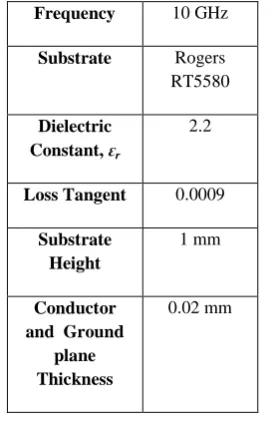
microstrip patch antenna the height of the dielectric substrate is critical since the antenna should not be bulky. The transmission line model will be used to design the antenna [8].The edge type feed is used in this design. The design characteristics of this array are shown in Table I.
TABLE I.DESIGN CHARACTERISTICS OF MICROSTRIP ARRAY ANTENNA 10 GHz Frequency Rogers RT5580 Substrate 2.2 Dielectric
Constant, ԑr
0.0009 Loss Tangent 1 mm Substrate Height 0.02 mm Conductor
International Journal of P2P Network Trends and Technology (IJPTT) – Volume 5 Issue 2 March to April 2015
Individuial patch Design Calculations A) Fringes factor:
B) Calculation of length:
Where
B) Calculation of Width:
For efficient radiation, the width W is given as[9]
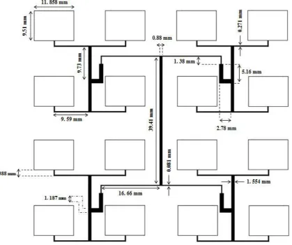
B. Structure of Array Antenna
The 4x4 array is shown in Fig. 2. This array feeding method is corporate. Since there are multiple radiating elements, they have to connect in some sort of fashion. Corporate parallel
feeding network are used to provide power splits for 2n elements which can be applied to the 16 elements. It was found suitable to select a thin dielectric substrate with low dielectric constant by considering the trade-off between the antenna dimensions and its performance.Thin substrate permits to reduce the size and also spurious radiation as surface wave, and low dielectric constant – for higher bandwidth, better efficiency and low power loss. After some calculations it was agreed to use Rogers RT duroid with r=2.2 and the thickness of 1 mm for substrate.
Also, structure of array in CST is shown in Fig .1. The ground plane dimensions are 79 mm x 79 mm .
Fig .1 Design array antenna in CST
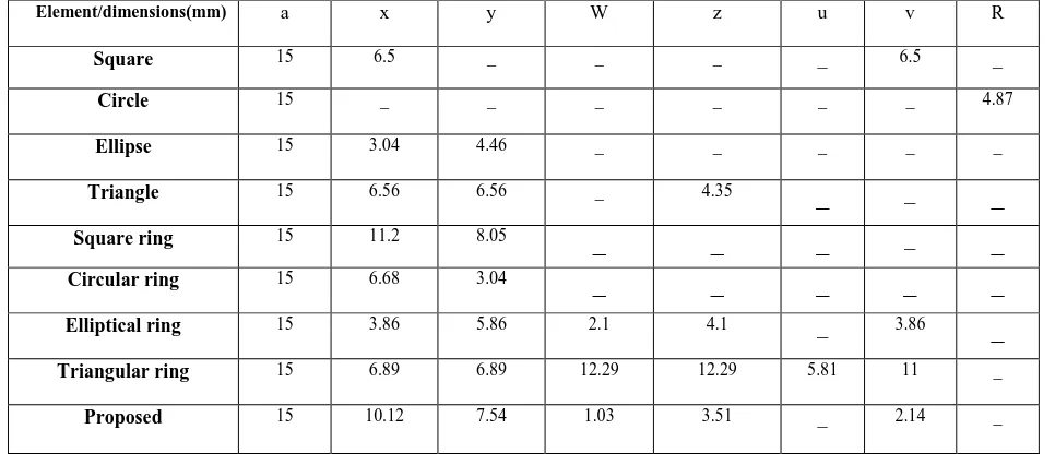
TABLE II.DIMENSION OF EACH ELEMENT
Element/dimensions(mm) a x y W z u v R
Square 15 6.5 _ _ _ _ 6.5 _
Circle 15 _ _ _ _ _ _ 4.87
Ellipse 15 3.04 4.46 _ _ _ _ _
Triangle 15 6.56 6.56 _ 4.35
_
__
Square ring 15 11.2 8.05
_
_
_
__
Circular ring 15 6.68 3.04
_
_
_
_
_
Elliptical ring 15 3.86 5.86 2.1 4.1 _ 3.86
_
Triangular ring 15 6.89 6.89 12.29 12.29 5.81 11 _
Fig. 2 Corporate Feeding Method for Array
International Journal of P2P Network Trends and Technology (IJPTT) – Volume 5 Issue 2 March to April 2015
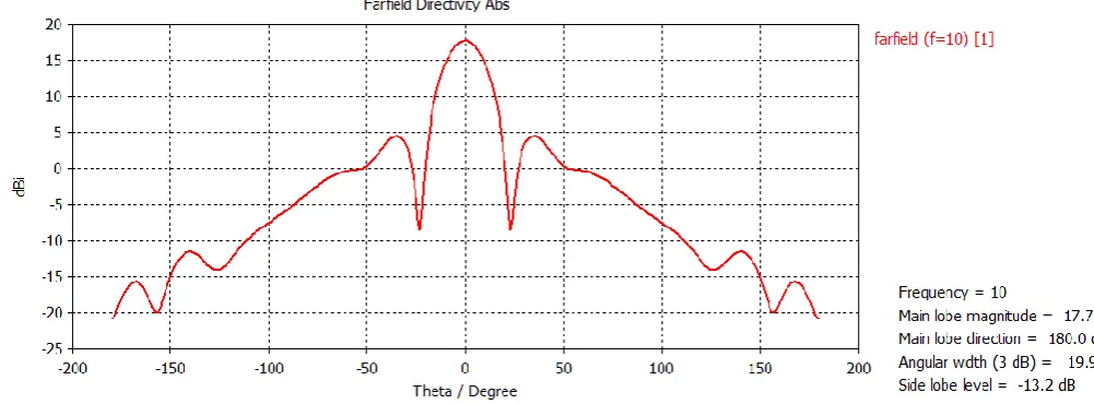
Fig. 4 Cartesian plot of patch array antenna
From the figure above, the acheived gain was 17.7 dB for peak gain at 10GHz. This is absloutely a considerable amount which is completely better than a horn. The reason is hardship in making a horn witch consist of a waveguide and an aperture cost so much time and also needs more financial budget compared to microstrip antenna array. Therefore, this kind is a suitable choice as feed.
C. Reflectarray Element Design
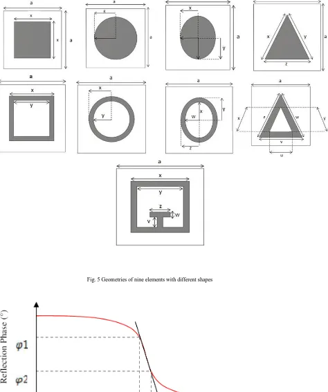
The reflectarray elements are designed to be operated at X-band with nine different shapes comprising Square, Circle, Ellipse, Triangle and loop of them. Fig. 5 shows the details design for each element used in this experiment. Each design has passed through an optimization process to get the exact nominal value so that all designs are resonated around 10 GHz frequencies. Table 2 shows the detail dimensions of each design respectively. Fig. 5 shows nine different elements shape and dimensions in parameters which are given in Table 2. The Rogers RT/Duroid 5880 substrate layer of 1 mm thickness is used to support above layer which is conductor thickness t=0.02 mm
(PEC is used for patch material). Meanwhile, PEC layer at the bottom of the RT 5880 substrate acts as a ground plane which has the same thickness as conductor layer.
III.RESULTSANDDISCUSSIONS
International Journal of P2P Network Trends and Technology (IJPTT) – Volume 5 Issue 2 March to April 2015
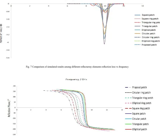
Fig. 7 Comparison of simulated results among different reflectarray elements reflection loss vs frequency
Fig. 8 Comparison of simulated results among different reflectarray elements reflection Phase vs frequency
Fig. 6 shows the reflection phase versus frequency which can be used to calculate the phase slope of each element. the phase slope can be obtained by Equation 1
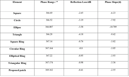
Table III summarizes the detail results of the phase range as well as the reflection loss values for each element. It can be observed that triangular element has the highest reflection loss of -4.18 dB which has the
contributes the largest loss. Also, the propped element has the lowest slope which is about -2.55 that has an important effect on increasing bandwidth. In addition, the Elliptical element has steepest slope which is -10.709 that can have destructive influence on bandwidth. Therefore, the proposed element can be a suitable candidate as a reflectarray element.
Now we are going to design reflectarray antenna using the proposed element. The reflectarray antenna consists of 100 elements which are shown in Fig. 7. Rogers RT/Duroid 5880 with r=2.2 is used as
The fact is feed blockage can be omitted when using the feed in offset position. So, antenna parameters such as gain, directivity… will have better characteristics in this situation.
Table III summarizes the detail results of the phase range as well as the reflection loss values for each element. It can be observed that triangular element has the highest reflection loss of -4.18 dB which has the lowest bandwidth. Meanwhile, it is observed that highest bandwidth offered by proposed element which has the lowest reflection loss. Conversely, the lowest bandwidth happens at triangular element as it contributes the largest loss. Also, the propped element has the lowest slope which is about -2.55 that has an important effect on increasing bandwidth. In addition, the Elliptical element has steepest slope which is -10.709 that can have destructive influence on
bandwidth. Therefore, the proposed element can be a suitable candidate as a reflectarray element.
Now we are going to design reflectarray antenna using the proposed element. The reflectarray antenna consists of 100 elements which are shown in Fig. 7. Rogers RT/Duroid 5880 with r=2.2 is used as
substrate and the thickness is 1 mm. The center frequency is 10 GHz, so the wavelength is about 3 cm. Also, length and width of each unit cell in the reflectarray is about 15 cm. The suitable position for microstrip array feed is in offset mode witch is completely out of the region of reflectarray antenna. The fact is feed blockage can be omitted when using the feed in offset position. So, antenna parameters such as gain, directivity… will have better characteristics in this situation.
Table III
Simulated phase range, reflection loss and phase slope of different resonant elements.
Element Phase Range / Reflection Loss/dB Phase Slope(α)
Square 366.69 -2.65 -6.23
Circle 366.52 -3.19 -7.92
Ellipse 366.007 -3.58 -10.709
Triangle 366.28 -4.18 -9.42
Square Ring 367.14 -0.76 -3.02
Circular Ring 367.164 -0.8 -3.05
Elliptical Ring 367.22 -0.95 -3.93
Triangular Ring 367.174 -0.98 -3.36
International Journal of P2P Network Trends and Technology (IJPTT) – Volume 5 Issue 2 March to April 2015
Fig. 9 the reflectarray antenna using proposed element and the microstrip array feed
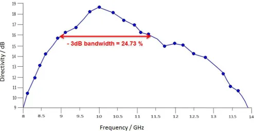
Fig. 11 -3dB bandwidth of the reflectarray antenna
As can be seen in Fig. 10 the directivity of this antenna is about 18.84 dB. Also, -3dB bandwidth is about 24.73 % which is suitable compared to other elements(Fig. 11).
IV.CONCLUSION
By considering this paper it was concluded that the proposed element is a suitable choice as a reflectarray element. Also, a proper -3dB bandwidth was achieved which is about 24.73 %. The reason is that the bandwidth of the whole antenna depends on the individual element. Therefore the bandwidth is influenced by the element.
V. REFERENCES
[1]. J. Huang , ― Microstrip reflectarray , ‖ IEEE AP - S/URSI symposium, London, Canada, June 1991 , pp. 612 –615 . [2]. D. M. Pozar and T. A. Metzler, ―Analysis of a reflectarray
antenna using microstrip patches of variable size,‖ Electronics Letters, April 1993, pp. 657 – 658.
[3]. J. Huang , ― Bandwidth study of microstrip reflectarray and a novel phased reflectarray concept , ‖ IEEE AP - S/URSI symposium, Newport Beach, California, June, 1995 , pp. 582 – 585 .
[4]. M. Bozzi , S. Germani , and L. Perregrini , ― Performance comparison of different element shapes used in printed
reflectarrays ‖ , IEEE Antennas and Wireless Propagation Letters , Vol. 2 , pp. 219 – 222 , 2003 .
[5]. Garg, R., P. Bhartia, I. Bahl, and A. Ittipiboon, Microstrip
Antenna Design Handbook, Artech House, Norwood, MA,
2001.
[6]. Owens, R. P., "Microstrip Antenna Feeds," in Handbook of Aficrostrip Antennas, Vol. 2, J. R. James and P. S. Hall (Eds.), Peter Peregrinus, London, UK, 1989.
[7]. Kummer, W. H., "Feeding and Phase Scanning," in Microwave Scanning Antennas, Vol. III, R. C. Hansen (Ed.), Academic Press, New York, 1966.
[8]. Qing-Yong Chen, Shi-Wei Qu, Jian-Feng Li, Qiang Chen, ―An X-Band Reflectarray with Novel Elements and Enhanced Bandwidth‖ IEEE ANTENNAS AND WIRELESS PROPAGATION LETTERS, VOL. 12, 2013 , pp.317-320. [9]. Siti Hafizah Yusop, Norbahiah Misran, Mohammad Tariqul
Islam, and Muhammad Yusof Ismail, ―Development of A Single Square Ring Reflectarray Element for Bandwidth Enhancement‖ 2011 International Conference on Instrumentation, Communication, Information Technology and Biomedical Engineering 8-9 November 2011, Bandung, Indonesia.