Available Online at www.ijpret.com 33
INTERNATIONAL JOURNAL OF PURE AND
APPLIED RESEARCH IN ENGINEERING AND
TECHNOLOGY
A PATH FOR HORIZING YOUR INNOVATIVE WORK
NOISE ATTENUATION IN TRANSFORMERS
HITESH PAGHADAR1, DR. R. A. KANTARIA2
1. Research Scholar, Rai University, Ahmedabad 2. Associate Prof., V.V.P. Engineering College, Rajkot
Accepted Date: 27/02/2016; Published Date: 01/03/2016
\
Abstract: - Transformer is the main equipment in transmission and distribution system.
Transformers in service generate a characteristic sound, classified as noise by people residing near these transformers. The origin of the noise is the core vibration because of magnetostriction, which is mechanical effects in core by the alternating flux. Other sources of noise are winding vibration and tank walls. This paper presents the several ways to control the transformer noise generation and transmission to the air. Further, it presents the outcomes of software analysis case study conducted on flux density reduction by increasing only yoke C/S area of core. It’s a novel technique for transformer noise control.
Keywords:Transformer, Noise controls
Corresponding Author: MR. HITESH PAGHADAR
Access Online On:
www.ijpret.com
How to Cite This Article:
Hitesh Paghadar, IJPRET, 2016; Volume 4 (7): 33-41
Available Online at www.ijpret.com 34
1. INTRODUCTION
Sound is defined as any pressure variation that the human ear can detect ranging from the weakest sound to the levels that could impair hearing. Increasing environment noise pollution is a matter of great concern and of late has been attracting public attention. Sound produces the minute oscillatory changes in air pressure and is audible to the human ear when in the frequency range of 20Hz to 20kHz. When its level exceeds a certain threshold level, it may impair hearing ability of the living beings. Therefore acceptable sound levels are specified by ordinances of indian Government and product standards like NEMA TR-1 and CBIP Manual on Transformers.
2. NOISE GENERATION CONTROLS
a. Design Control
The sources of transformer sound are magnetostriction in core, winding vibration because of electromagnetic forces, tank walls, and magnetic shunts, cooling equipments. Magnetostriction was found to play the major part in noise production and it depends on flux density. Magnetostriction is a term used for the small mechanical deformations of core laminations in response to the application of a magnetic field. The frequency of transformer sound is double of the supply power frequency. Variation of 10 percentage in the flux density relative to the rated value produces on an average a difference of about 3 dB(A). Magnetostriction is directly propotional to the flux density.
Some design controls like, CRGO sheets with low magnetostriction, Low flux density, low core weight, Use of step-lap core construction, Use of thick laminat sheets, Use of rib type of stiffeners, Use of lower speed cooling fans, etc are gives the significant effect on noise level.
b. Manufacturing Controls
Available Online at www.ijpret.com 35
3. NOISE TRANSMISSION CONTROLS
3.1 Internal controls
The ideal solution would be to place dampers at all mechanical joints, and to line the interior of the tank with sound absorbent material (like press board). Anti-vibration pad is used below the feet of core assembly to reduce the structureborne sound transmission to tank. It gives the reduction in tank vibration by restricting core vibrations to itself through anti-vibration pad and hence sound level.
3.2 External controls
3.2.1 Active Noise Suppression:
The active noise suppression is tried to achieve 100 percent noise cancelation of transmitted noise. In this technique, the anti-phase noise is generated and superimposed on the noise emitted by the transformer. The fig 3.1, below shows the principal of active noise control. The noise reduction using this technique will depend on area of source of noise and no. of units installed near the transformer. Further, it requires very sophisticated instrumentation and computational facilities. The main problems of this approach is to provide sufficient no. of loudspeakers and microphones at appropriate positions, to cancel the emitted transformer noise. The experimental case studies on transformers did not yield the derived results, thus precluding its practical viability for transformer application.
Fig.3.1 Principal of Active Noise Suppression
3.2.2 Damping material between Stiffeners
Available Online at www.ijpret.com 36
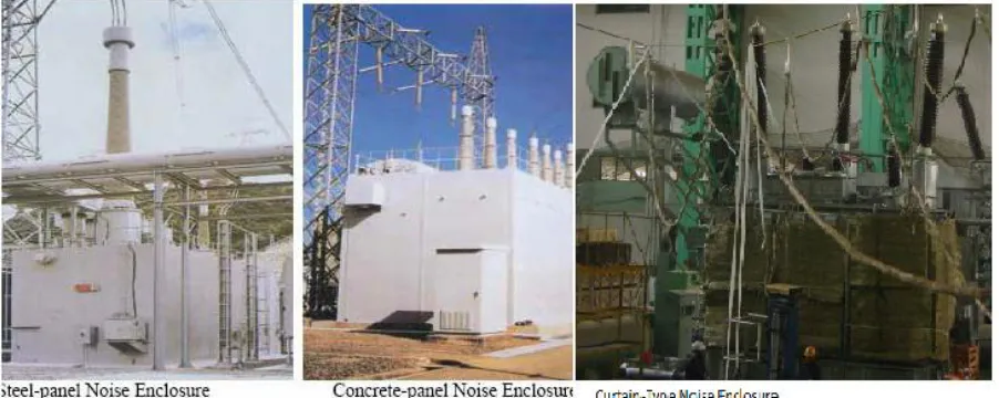
3.2.3 Noise Enclosure
When a transformer is installed close to the boundary line of a power station/substation, or when several transformers are installed at the same station, it may be necessary to dampen transformer sound by providing different types of enclosures, as shown in fig 3.2.
Fig. 3.2. Different Types of Enclosures
3.2.4 Ground-borne noise transmission
Sound and vibration from large transformers are also transmitted via the ground. Ground-borne vibrations cause adjacent structures to vibrate, which may then amplify and retransmit the sound. These effects can be reduced by placing the transformer on anti-vibration mounting- strips of rubber or other resilient material. The damping material could be also provided between foundation of transformer and other equipment’s to reduce ground-borne sound transmission.
4. CASE STUDY FOR NOISE GENERATION CONTROL AT DESIGN STAGE
Available Online at www.ijpret.com 37
and if winding diameter exceeds 6m, then radial vibration will come in picture. Based on the above, analytical studies is carried out by increasing top and bottom yoke cross-sectional area and resluts is compared with the software analysis. it is novel technique for controlling sound level at design stage.
a. Analytical Study:
For the purpose of carrying out analytical study, a 100 MVA, 220/66 kV, 3-Phase, 50 Hz Power transformer is identified. In order to study influence of change in flux density by 10 percent of the original value on the sound level, design novel technique is chosen. The results obtained is compared with the reference design and placed at Table I. The merits and de-merits associated with new methods are placed at Table II.
Sr.No. Design Parameters Reference Design Modified Design
1 Core dia. (cm) 80 84
2 Flux density (T) 1.6 1.44
3 Volt/turn (volt) 165 165
4 No.of turn in
winding
HV 1340 1340
LV 402 402
5 Material Grade M4 M6
6 Thickness (mm) 0.27 0.30
7 Core weight (kg) 55442.77 61453.12
8 Specific loss (W/kg) 1 0.9
9 No-load loss (kW) 55.44 55.30
10 Reduction in sound level 2.95 dB(A)
Table-I
Design Advantages Disadvantages
Available Online at www.ijpret.com 38
Increased lamination sheet thickness
Low cost
Table-II
The change in sound level with respect to flux density was calculated using equation 5.1.
where, B1,W1=reference flux density & core weight, B2,W2=desired flux density & core weight.
Above equation shows the flux density is a dominant factor for sound level control than core weight and hence reduced flux density gives the low sound level with somewhat increased core weight.
4.2 Software Analysis
For the purpose of carrying out software analysis, a 100 MVA, 220/66 kV, 3-Phase, 50 Hz Power transformer is identified as a reference design, which is same as for Analytical study. In order to carried out the magnetostatic analysis, Ansoft maxwell 2D version is chosen. Drawing model with dimension of transormer core & winding is shown fig.4.1.
Available Online at www.ijpret.com 39 Fig. 4.2 Ansoft Maxwell 2D analysis of Reference Design
Fig.4.2 shows the Magnetostatic analysis using Ansoft Maxwell 2D software with Reference design of Transformer. It gives 1.55 Tesla average flux density and found reasonably closer to the result of analytical study.
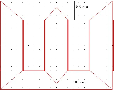
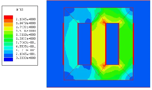
Now, in order to reduce the flux density, C/S area of top and bottom yoke is increased, shown in fig.4.3 and then again analyzed with this modified design of Transformer like increased yoke C/S area, 0.30 mm lamination sheet thickness and M6 core material shown in fig.4.4. it gives 1.4 Tesla average flux density. Based on above results, Magnetoststic analysis gives 2.82 dB(A) sound level reduction, using equation 5.1.
Available Online at www.ijpret.com 40 Fig. 4.4 Ansoft Maxwell 2D Analysis of Modified Design
b. Observations:
Comparision of the results carried out by the Analytical study and software analysis is placed at Table-III. It is observed that reduction of sound level to the tune of 2 to 3 dB(A) with the reduction of 10% flux density by using novel technique, increasing only yoke C/S area.
Analysis Reference Design Modified Design Reduction in Sound level
Analytical B = 1.6 T B = 1.44 T 2.95 dB(A)
Software B = 1.55 T B = 1.4 T 2.82 dB(A)
Table -III
5. CONCLUSION
From the foregoing, it could be concluded that the modified method of sound level reduction gives the economical design with 2 to 3 dB(A) low sound level, thick lamination sheet, low cost, 10% low flux density to meet the contractual requirements.
6. REFFERENCES
1. Hsu, Chang Hung, High frequency characteristics of magnetostriction on vibration and noise
Available Online at www.ijpret.com 41
2. Lee, Chang yao, cheng, Effect of magnetostriction and magnetic reluctances on magnetic
properties of distribution transformers, Journal of Applied science, Vol.115, IEEE, May-2014.
3. Matshediso Phoshoko, Power transformer noise:sources, factors and remedies, Powertech
Transformers, Powertech Transformer Ltd., energize- August-2013.
4. Abhinavkumar, Causes of noise generation & its mitigation in Transformer, Journal of
Environmental science and Engineering & Technology, vol.2, 75-79, 2013.
5. S.V.Kulkarni, S.A.Khaparde, Tansformer Engineering Design, Technology & Diagnostics,
Second Edition, CRC press, 2013.
6. James H. Harlow, Electric Power Transformer Engineering, The Electric Power Engineering
Handbook, Third Edition, CRC Press, Taylor & Francis Group, 2012.
7. Ramsis Girgis, Mats Bernesjo, The corporate technical journal, ABB review special report
transformers, ABB Group R & D and Technology, November-2012.
8. Ramsis Girgis, jan Anger, Donald Chu The Sound of Silence, Designing and producing silent
transformers. ABB review, February-2008.
9. Manual on Transformers. Publication No.-295, Central Board of Irrigation and Power (CBIP),
March-2006.
10. Power transformers determination of sound levels. IEC 60076-10 International standard,
first edition 2001-05.
11. Transformers, Regulators and Reactor National Electrical Manufacturers Association