Organized by C.O.E.T, Akola. Available Online at www.ijpret.com515
INTERNATIONAL JOURNAL OF PURE AND
APPLIED RESEARCH IN ENGINEERING AND
TECHNOLOGY
A PATH FOR HORIZING YOUR INNOVATIVE WORKSOLAR CHARGING STATIONS – A NEED OF AN HOUR
SANJAY N. NAIKWAD1, JYOTI P. DHUMALE2
1. Department of Electrical Engineering, College of Engineering & Technology, Akola 2. Department of Chemistry, College of Engineering & Technology, Akola
Accepted Date: 12/03/2016; Published Date: 02/04/2016
Abstract:With ever increasing demand of energy, fast depletion of conventional energy sources and considering associated environmental problems, scientists are looking forward to tap solar energy as an alternative. On this ground, electric vehicles also gaining momentum. Automotive batteries and other storage batteries require charging in safe and cost effective manner. Role of charging station in this context is very important. This paper highlighted various issues related to charging stations and their performance and also discusses the need of solar charging stations in current changing scenario.
Keywords: Charging Stations, Electrical Vehicle (EV).
.
Corresponding Author: MR. SANJAY N. NAIKWAD Co Author: MS. JYOTI P. DHUMALE
Access Online On:
www.ijpret.com
How to Cite This Article:
Sanjay N. Naikwad, IJPRET, 2016; Volume 4 (8): 515-529 PAPER-QR CODE
SPECIAL ISSUE FOR
NATIONAL LEVEL CONFERENCE
"RENEWABLE ENERGY
Organized by C.O.E.T, Akola. Available Online at www.ijpret.com516
INTRODUCTION
Continuous development in the field of electrical energy storage devices and innovations in battery charging technology enabled us to develop charging stations. Such charging stations are successfully deployed at various places in developing countries. As conventional sources for electrical energy generation are depleting very fast and on other side demand for energy is ever increasing, it became difficult to achieve economic viability of charging stations in techno-commercial world. Owing to shortage of energy from conventional source, alternative sources of energy were searched and thus solar, wind and bio energy emerged as viable options. Development in PV technology with increasing efficiency and decreasing solar cell cost has paved a way for its use in charging stations.
A. Current Scenario
As per the data published on charging stations, around 50,000 non residential charging points are deployed in USA, Europe, Japan and China till December 2012. Up to August 2014, 3869 fast charging utilities were deployed around the world. United States leads in public charging stations deployed followed by developed countries in Europe. Norway, which has the highest electric vehicle ownership per capita, had 4029 charging points and 127 quick stations. Dutch government recently deployed 200 fast (DC) charging stations. Japan turned out as a country with highest ratio of quick chargers for electric vehicles. On the other hand China, Netherlands and USA has highest ratio of slow chargers.
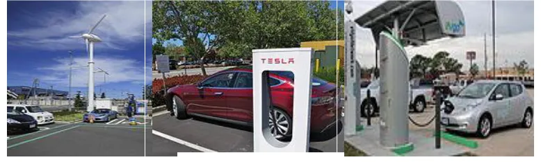
Figure 1: Different charging stations
B. Renewable electricity and RE charging stations
Organized by C.O.E.T, Akola. Available Online at www.ijpret.com517 installations. The company has announced a partnership with “Rabobank” to make electric car charging available for free to owners of “Tesla Motors” vehicles. The “SPARC” (Solar Powered Automotive Recharging Station) uses a single custom fabricated mono-crystalline solar panel capable of producing 2.7 KW of peak power to charge pure electric or plug-in hybrid to 80% capacity without drawing electricity from the local grid. Plans for the SPARC include a non-grid tied system as well as redundancy for tying to the non-grid through a renewable power plan. This supports their claim for net-zero driving of electric vehicles. The E-Move Charging Station is equipped with eight mono-crystalline solar panels, which can supply 1.76 KW of solar power. With further refinements, the designers are hoping to generate about 2000 kWh of electricity from the panels over the year. In 2012, “Urban Green Energy” introduced the world's first wind-powered electric vehicle charging station. The design features a 4 kW vertical-axis wind turbine paired with a GE Watt Station. This paper presents an overview of all the factors which leads to development of charging stations and utility of solar charging stations in developing countries in current scenario.
II. Charging Station
Charging station is an element in an infrastructure which is used to supply electrical energy for recharging batteries used in vehicles and other applications. Due to cost of electrical energy and its proven use to almost all applications, battery is commonly used as a storage device and thus there is a growing need for widely distributed publicly accessible charging stations. Depending upon need for charging of electrical vehicles in particular, charging stations falls into four basic contexts
1. Residential Charging Station: It is a unit applied at residence where electrical vehicle owner
plugs in when he or she returns home and the car recharges over night.
2. Charging While Parking: It is small public charging station applied in parking area where
owner of vehicle recharges battery with a high and low speed. This is a commercial venture where metering system is applied to get required fee.
3. Fast Charging Station: It is a commercial venture applied on road side or highways where
fast charging is done in 10 to 30 minutes so as to deliver 60 to 100 KM of range. This can be used by commuters in metropolitan areas also.
4. Battery Swap: These utilities charges battery within 15 minutes. This scheme was not
Organized by C.O.E.T, Akola. Available Online at www.ijpret.com518
A. Safety and Norms
Although the rechargeable electric vehicles and equipment can be recharged from a domestic wall socket, a charging station is usually accessible to multiple electric vehicles and has additional current or connection sensing mechanisms to disconnect the power when the electric vehicle is not charging. There are two main types of safety sensors. Current sensors, the one which monitor the power consumed, and maintain the connection only if the demand is within a predetermined range. Additional physical 'sensor wires' which provide a feedback signal such as specified by the SAE J1772 and IEC 62196 schemes that require special (multi-pin) power plug fittings. Design of charging stations should be in accordance with safety norms and standards. In SAE terminology, 240 volt AC charging is known as Level 2 charging, and 500 volt DC high-current charging is known as DC Fast Charge. Owners can install a level 2 charging station at home, while businesses and local government provide level 2 and DC Fast Charge at public charging stations that supply electricity for a fee or free.
Need for charging stations highly influenced by electric vehicle use and amount of battery charging requirement. Although the rechargeable electric vehicle requirement can be charged from domestic wall socket but charging stations has additional current or connection setting mechanisms which ensure safe and required charging. Charging stations enriched with all necessary sensing and protective circuits for their reliable safe and cost effective operations.
Conventional energy sources are depleting very fast. The world is now moving towards use of renewable energy sources. In this context along with developed countries developing country like India trying to tap solar and wind energy and using them for commercial applications. These sources need energy storing devices like batteries for their efficient use. This also leads to development of electrical vehicles in developing countries. Commercial use of electrical vehicles largely depends upon cost of charging. Hence efforts are being made to optimize parameters influencing operation of charging stations.
B. EV (Electric Vehicle) Charging Stations
Organized by C.O.E.T, Akola. Available Online at www.ijpret.com519 Power Factor Correction (PFC) chargers can more closely approach the maximum current the plug can deliver, shortening charging time.
Battery charging technology
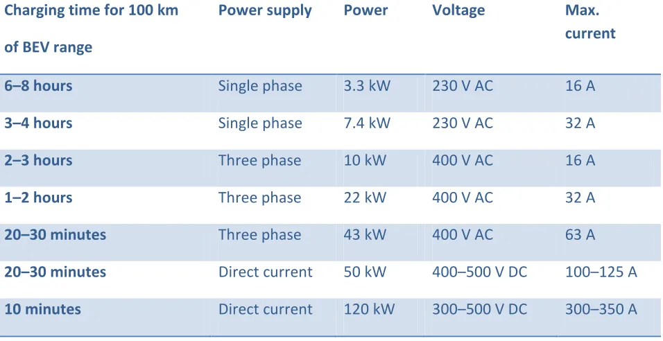
Factors influencing performance and efficiency of the charging station are 1) Charging time, 2) Charge control, 3) Charging methods and 4) Charge rate. The battery capacity of electrical vehicle is about 20 KWh as per the data obtained from Nissan. Tesla Motors developed range of batteries having capacities 40 to 85 KWh. Plug in hybrid vehicles have capacity of roughly 3 to 5 KWh which caters need up to 20 to 40 KM. For normal charging up to 7.4 KW, car manufacturer have build a battery charger into the car itself. It just requires 230V AC supply to connect it for charging. For quicker charging particularly in high powered vehicles (22KW and more) manufacturers used built in charger which works on 230V single phase or 400V three phase supply. Also some manufacturers use external chargers which convert AC current to DC current to achieve fast charging. The following table gives estimates of charging time for different range of parameters.
Charging time for 100 km
of BEV range
Power supply Power Voltage Max. current
6–8 hours Single phase 3.3 kW 230 V AC 16 A
3–4 hours Single phase 7.4 kW 230 V AC 32 A
2–3 hours Three phase 10 kW 400 V AC 16 A
1–2 hours Three phase 22 kW 400 V AC 32 A
20–30 minutes Three phase 43 kW 400 V AC 63 A
20–30 minutes Direct current 50 kW 400–500 V DC 100–125 A
10 minutes Direct current 120 kW 300–500 V DC 300–350 A
Table 1: Charging time for different range of parameters
Organized by C.O.E.T, Akola. Available Online at www.ijpret.com520 to adjust as per need of customer and availability of power which ensures optimum effort. Hardware used in charge control also monitors the vehicle and helps in peak load leveling. Charge rate signifies a charge or discharge rate equal to the capacity of battery in one hour. A battery charger is generally specified with battery capacity or ‘C’ rate. A charger rated at 4C would charge the battery in 15 minutes where as charger rated C/10 would charge battery in 10 hours. Very rapid charging rate require careful monitoring of terminal voltage and temperature to prevent overcharging and damage to cells. Rechargeable battery is a key element which decides performance of electric vehicle. Indicators which decide the health of battery are SOC (state of charge), DOD (depth of discharge) and SOH (state of health). Careful monitoring and control of these indicators using charge control and charge rate improves performance and life of a battery.
A. Basic Charging Methods
1. Constant Voltage: It is a constant voltage charger provided through DC power supply. The
lead-acid cells used for cars and backup power systems typically use constant voltage system. Lithium-ion cells often use constant voltage system, although they need added circuitry to protect due to their complexity.
2. Constant Current: These chargers vary the voltage they apply to the battery to maintain
constant current flow and switching off when the voltage reaches the level of full charge. This method found suitable for nickel-cadmium and nickel metal hydride batteries.
3. Taper Current: This method involves charging from a crude unregulated constant current
source. The current diminishes as the cell voltage builds up. Suitable for SLA batteries only.
4. Pulsed Charge: This method feeds charge current to the batteries in pulses. The charging
rate here can be precisely controlled by varying the width of pulses.
5. Burp Charging: It is called reflex or negative pulse charging. It is used in conjunction with
pulse charging where it applies very short discharge pulse. These pulses discharges any gas bubbles which have built up on the electrodes during fast charging, speeding up stabilization process and hence overall charging. The release and diffusion of gas bubbles called “Burping”.
6. ICU Charging: It is recently developed method which is used for fast charging of standard
Organized by C.O.E.T, Akola. Available Online at www.ijpret.com521
7. Trickle Charge: This method is designed to compensate for the self discharge of the battery.
The charge rate varies according to frequency of discharge. Not suitable for Ni-MH and Lithium batteries.
8. Float Charge: In this method, the battery and the load are permanently connected in
parallel across the DC charging source and they are held at constant voltage which lies below the upper voltage limit of a battery.
9. Random Charging: There are many applications where energy to charge the battery is
available in some random, uncontrolled way. This applies to automobile applications where the energy depends on the engine speed which is continuously changing.
Based on above methods of charging manufacturers developed battery charger like simple charger supplying constant DC or pulsed DC power, fast chargers with control circuitry, inductive chargers, intelligent charger (also called smart charger), pulse charger, time based charger, Trickle charger, Universal battery charger analyzes, USB based chargers etc.
B. Charging Rates
Batteries can be charged at different rates depending on the requirement. Typical rates are shown below:
Slow Charge = Overnight or 14-16 hours charging at 0.1C rate
Quick Charge = 3 to 6 Hours charging at 0.3C rate
Fast Charge = Less than 1 hour charging at 1.0C rate
For automotive batteries the charging time may be limited by the available power rather than the battery characteristics. Domestic 13 Amp ring main supply circuit can only deliver 3KW. Thus, assuming no efficiency loss in the charger, a ten hour of charging could put 30 KWh of energy into the battery which is enough for about 100 miles.
Thus, in order to charge battery quickly, quick/fast charging methods are needed to be applied. But as the charging rate increases, so do the dangers of overcharging or overheating the battery. Preventing the battery from overheating and terminating the charge when the battery reaches full charge become much more critical.
Organized by C.O.E.T, Akola. Available Online at www.ijpret.com522 charger that was designed for another cell chemistry. Universal chargers, which are capable of charging all cell types, must have sensing devices to identify the cell type and apply the appropriate charging profile.
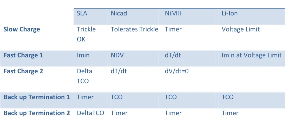
C. Charge Termination Methods
The following chart summaries the charge termination methods for popular batteries.
Charge Termination Methods
SLA Nicad NiMH Li-Ion
Slow Charge Trickle OK
Tolerates Trickle Timer Voltage Limit
Fast Charge 1 Imin NDV dT/dt Imin at Voltage Limit
Fast Charge 2 Delta TCO
dT/dt dV/dt=0
Back up Termination 1 Timer TCO TCO TCO
Back up Termination 2 DeltaTCO Timer Timer Timer
Table 2: Charge Termination Methods
TCO = Temperature Cut Off, Delta TCO = Temperature rise above ambient, I min = Minimum current
D. Charge Control Methods
Regular (slow) charge
Semi constant current is a simple, economical and most popular method. Low current does
not generate heat but is slow. It takes 5 to 15 hours typical. Charge rate 0.1C. Suitable for Ni-cads.
Timer controlled charging method is simple and economical. More reliable than semi-constant
current. Uses IC timer. The incorporation of an absolute temperature cut-off is recommended. Suitable for Ni-cad and Ni-MH batteries.
Organized by C.O.E.T, Akola. Available Online at www.ijpret.com523
Negative delta V (NDV) Cut-off charge system is the most popular method for rapid charging
for Ni-cads.
Figure 3: Characteristics of Ni-Cad, Ni-MH and Lithium-Ion batteries
Batteries are charged at constant current of between 0.5 and 1.0 C rate. The battery voltage rises as charging progresses to a peak when fully charged then subsequently falls. This voltage drop, -delta V, is due to polarization or oxygen build up inside the cell. The voltage drop occurs regardless of the discharge level or ambient temperature and it can therefore be detected and used to identify the peak and hence to cut off the charger when the battery has reached its full charge or switch to trickle charge.
dT/dt Charge system is used for Ni-MH batteries which do not demonstrate such a
pronounced NDV voltage drop when they reach the end of the charging cycle. Instead the charger senses the rate of increase of the cell temperature per unit time. When a predetermined rate is reached the rapid charge is stopped and the charge method is switched to trickle charge.
Constant-current Constant-voltage (CC/CV) controlled charge system is used for charging
Organized by C.O.E.T, Akola. Available Online at www.ijpret.com524 increase in unison with the cell voltage to overcome the back EMF of the cell as it charges up. This occurs quite rapidly during the constant current mode until the cell upper voltage limit of the cell is reached, after which point the charging voltage is maintained at that level, known as the float level, during the constant voltage mode. During this constant voltage period, the current decreases to a trickle charge as the charge approaches completion. Cut off occurs when a predetermined minimum current point, which indicates a full charge, has been reached.
Voltage controlled charging is carried out at charging rates between 0.5 and 1.0 C. The
charger switched off or switched to trickle charge when predetermined voltage has been reached. Should be combined with temperature sensors in the battery to avoid overcharge or thermal runaway.
V- Taper controlled charge system is similar to Voltage controlled system. Once a
predetermined voltage has been reached the rapid charge current is progressively reduced by reducing the supply voltage then switched to trickle charge. Suitable for SLA batteries.
Failsafe timer method limits the amount of charge current that can flow to double the cell
capacity.
Pre-charging method is applied as a safety precaution with high capacity batteries. The
charging cycle is initiated with a low current. If there is no corresponding rise in the battery voltage it indicates that there is possibly a short circuit in the battery.
Intelligent Charging System integrates the control systems within the charger with the
electronics sensing and control which allow much finer control over the charging process. The benefits include faster and safer charging along with longer cycle life of a battery.
IV. SOLAR CHARGING STATIONS
Organized by C.O.E.T, Akola. Available Online at www.ijpret.com525 There are many battery charging stations deployed in world. These charging stations are limited by need, location and availability of power and techno-commercial viability. Cost of available electrical power and control capacity at these stations are main regulating factors affecting development of such charging stations.
In context of Indian subcontinent per capita use of electrical vehicle as far less than developed countries in the world. Due to ever increasing cost of conventional sources like petrol and diesel, researchers and technologists are thinking of using electric vehicle for transportation. These electrically controlled vehicles require battery as their main storage device. When it comes to application of electrical vehicle in real world, cost of battery charging and facility for charging (charging stations) are to be considered foe economic viability of the project. Thus main objective behind implementation of concept is to minimize cost of charging. Per unit cost of conventional electrical energy is also increasing day by day. Due to this limitation it becomes necessary to tap free sources of energy like solar, wind to meet the demand of energy. In Indian subcontinent region we get 300 sunny days in a year. This solar energy if tapped and utilized during day time it is possible to lower burden on conventional system and economic sustainability can be achieved. Development in PV technology and improved solar charger designs made it possible to reach the goal. Government in developing countries also promoting use of unconventional energy sources by offering subsidies and energy buy back policies. Excess solar energy generated can be transferred to main grid using net metering. In India, net metering policy is recently launched for grid connected solar PV system. In view of all these factors, there lies an enough scope to utilize solar charging stations on commercial ground and techno commercial viability of the system can be achieved. DC power is generated through PV conversion. This DC output from solar panel can be fed to charge the batteries through intelligent charge controller.
A. Solar charge controller
Solar charge controller is an electronics device connected between battery and solar panels. It is used to regulate charges flow from solar panels towards battery. In other words solar charge controller is used to control flow of charges from solar panels to battery. It provides protection from overflow of charges from solar panels to battery and it is also used to protect batteries from under voltages. Its mean solar charge controllers provide protection against under and over voltages of batteries in charging and discharging of batteries.
Organized by C.O.E.T, Akola. Available Online at www.ijpret.com526 Use of batteries with solar panels is usually not good. So to avoid failure of batteries before time solar charge controller is used. For example you have a 12 volt battery and you want to charge it with 12 volt solar panel. 12 volt solar panel outputs 17-20 volt. So this 17-20 volt may damage battery due to overcharging, because batteries maximum charging voltage is usually between 13.5 -14 volt. To avoid this issue we need to develop a regulator which can control flow of charge from solar panel towards battery. Solar charge controller is used for this purpose.
Simple solar charge controller: This type of solar charge controllers use analog electronics to
control flow of charges.
PWM based solar charge controllers: This type of solar charge controllers used microcontrollers to charge batteries through pulse width modulation method.
MPPT solar charge controllers: MPPT stands for maximum power point tracking. This type of
charge controller used MPPT techniques to charge battery from solar panels.
B. Selection of Solar charge controller
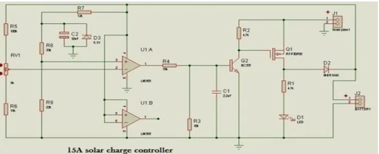
Figure 5: Circuit diagram of 15A solar charge controller
Organized by C.O.E.T, Akola. Available Online at www.ijpret.com527 The values of power and voltage are P = 200W and V = 18 V. By putting above values in power formula P = V*I, I = 200 / 18 = 11.11 Ampere. So, calculated value of current is 11.11A. Let’s suppose voltage of solar panels reduces to a lower value of 15 volt then current will increase, hence one should select a charge controller of little higher value than calculated.
Circuit diagram of 15A solar charge controller is shown in Figure 3. If one wants to use this circuit for higher rating, more than one solar charge controller in series are to be incorporated to increase current rating of charge controller. This circuit of charge controller used analog electronics instead of digital electronics.
C. MPPT charge controller
Organized by C.O.E.T, Akola. Available Online at www.ijpret.com528 voltages at all times, so that even on hot days, the expected voltage drop is still enough to put a charge into the battery.
ENVIRONMENTAL ASPECTS
Due to environmental degradation which takes place in so many last years, climate for living becoming unhealthy. Hence for sustainable living of mankind, world is now focusing on eco friendly devices and mechanisms. This also leads to development and use of clean sources of energy. Automotive related pollution is one of the great concerns in environmental issues. In this context, eco friendly vehicles like electric vehicles gaining momentum in these days. Automotive batteries are now developed by keeping environmental aspects in mind like problem of battery disposal and emission of gases during charging and discharging cycle. On the other hand to charge these automotive batteries, scientists are searching for clean sources of energy like wind and solar. Charging stations using wind and solar energy are installed by some reputed companies and their cost effectiveness is also proved.
INFERENCE
From the review of literature on battery charging, current trends in automotive sector, energy crisis and environmental issues, it is revealed that
Energy storage in battery is becoming integral part of EV (Electrical Vehicle) system and also
required for many day to day applications.
Charging of battery and its economics is limited by charging method, charge rate and charge
control. Choice of charging method, charge rate and control of system can be efficiently achieved using solar charge controller.
Solar powered system is suitable for fast charging and charge control can be effectively
exercised within required time.
Solar array dimension, capacity can be well adjusted with size requirement of charging
station and also the cost of infrastructure is less as compared to conventional one.
With solar charging station energy conversion cost during daytime is almost negligible.
Solar PV technology being green energy technology overcomes environmental issues.
Organized by C.O.E.T, Akola. Available Online at www.ijpret.com529
Excess energy generated by solar PV array can be fed back to grid through net metering
system. Thus 100% utilization of tapped solar energy is possible.
In view of all above observation it is inferred that there lies a great scope for development of solar charging stations in present scenario particularly in developing countries.
REFERENCES
1. Dunlop, James P., 1997, "Batteries and Charge Control in Stand-Alone Photovoltaic Systems:
Fundamentals and Application" Sandia National Laboratories, Photovoltaic Systems Applications Dept.
2. A Guide to Understanding Battery Specifications, December 2008, MIT Electric Vehicle Team,
3. Dianguina D., Mamadou S. D., Amadou D., Ousmane S., Idrissa G., Fabé I. B., Grégoire S.,
February 2013, “Development of Battery Charge/Discharge Regulator for Photovoltaic Systems”, International Journal of Innovative Technology and Exploring Engineering (IJITEE) ISSN: 2278-3075, Volume-2, Issue-3, pp 231-234.
4. S. Hamington, J. Dunlop, Aug. 2012, “Battery Charge Controller Characteristics in
Photovoltaic Systems”, IEEE journal of Aerospace and Electronics System Magazine, Vol. 7, Issue 8, pp 15-21.
5. E. Koutrioulis, K. Kalaitzakis, March 2004, “Novel Battery Charging Regulation System for
Photovoltaic Applications”, IEE proceeding on Electronic Power Application, Vol. 151,No. 2, pp. 191-197.
6. Naikwad S. N., Dudul S. V., Madansure V. N., Sep. 1997, “Microprocessor based maximum
solar energy tracker and scope for advanced computer techniques for photovoltaic system”, Proc. of Int. Conf. on Computer Application in Electrical Engineering – Recent Advances, CERA-97, pp 714-719.
7. Naikwad S. N., Kale D. G., Umale S. S., Jan. 1997, “An approach to solar wind energy in