*Corresponding author: AiméElime Bouboama
International Journal of
Current Multidisciplinary Studies
Available Online at http://www.journalijcms.com
Vol. 2, Issue,12, pp.512-519, December, 2016
RESEARCH ARTICLE
OPTIMIZING CONSOLIDATION COSTS OF COMPACTIBLE SOIL: AS APPLIED ON THE
CONSTRUCTION PROJECT OF THE SECOND WOURI BRIDGE IN CAMEROON
AiméElime Bouboama
1*., Mamba Mpele
2., Marcelline Blanche Manjia
3and
Audrey Towa Leann
41,2,3
Department of Civil Engineering and Urban Planning, National Advanced School of Engineering,
University of Yaoundé I, P.O. Box. 8390, Yaoundé, Cameroon
4
Departments of Industrial and Mechanical Engineering, National Advanced School of Engineering,
University of Yaoundé I, P.O. Box. 8390, Yaoundé, Cameroon
A R T I C L E I N F O A B S T R A C T Received 4th, September, 2016,
Received in revised form 5 th,
October, 2016, Accepted 24th, November, 2016, Published online 28th, December, 2016
The construction of infrastructure on compactible soil such as estuaries which feature very thick compactible alluvial deposits entails the mastery of the magnitude of compaction over time according to the importance of load applied. The Douala basin, especially the port area is made up of sandy and sandy argilous sedimentary soil with imbrications of loam layers, which make them highly compactible.This feature constitutes an instability factor for buildings constructed in this area, which calls for special precautions that may lead to considerable overcosts relating to earthworks (backfills carried out to reclaim land over the river) and special equipment (vertical drains, pillars, drilled micro-pillars). This article deals with the optimization of costs relating to the putting in place of drainage materials in the form of vertical drains as part of the construction project of the 2ndWouribridge in Douala,
Cameroon. After a mathematical modeling of the optimization problem, followed by its solution using the simplex method, a gain of72 829 690 frs CFA for the building of the foundation, 13 620 165 frs CFA for putting in place vertical drains and6 750 567 frs CFA for the putting in place of the draining layer.
Keywords:
optimization, costs, drains, compaction, compactible soil
INTRODUCTION
Construction works on compactible soil (saturated argilous) entail many hurdles, such as important compaction of infrastructure, instability of foundations and infrastructure built on highly compactible (low-resistant) saturated argilous soil. Areas with compactible soil can be treated using several technical solutions. The solution most commonly used for construction works is that of deep foundations. Emmanuel Kemongne (2007) showed that the method for stabilizing compactions through the progressive unidirectional loading could help to reduce between 20 to 50% the cost of the foundation of heavy infrastructure in the Douala area. This study further states that four years following the commissioning of the infrastructure, no damage was reported. However, this stabilization method is only efficient when the
loading and consolidation periods are incompatible with the project’s deadline.
Concerning the project for the construction of the second bridge on the WouriRiver where the consolidation period is still compatible with the provisional planning of works, pre-filling with vertical drains followed by compaction with equipment in order to accelerate compactible soil compaction and consolidation through a network of vertical drains was the method used.This treatment technique implies the use of borrowed materials (2/3of sand and1/3of pozzolanfor example). Conversely, using over thick material impacts the supply cost of materials, the cost of using equipment and the cost in manpower. Also, the deepness of drains depends on soil lithology.
Results of pressiometric tests (FP1, SPTFP1) on site (at the right side of C0 abutment) are summarized in Figure 1
IJCMS
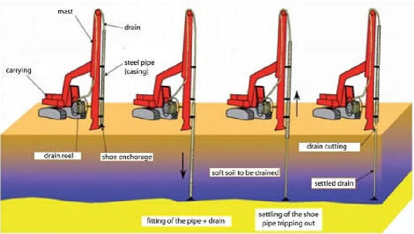
As part of soil consolidation works using vertical drains, the evaluation of optimum depth of drains during their construction, as well as the evaluation of necessary backfill optimum thickness is two important parameters. The consolidation phase using vertical drains in this area comprise of the basement of the platform, the construction of vertical drains and the putting in place of the draining layers (Figure 2).
The mandrelis inserted into the ground trough chains operated by hydraulic engines. The required construction depth is 20 m. Then, the drain is cut using a cutter in such a way as to leave a free height of about 25 cm above ground level (Figure 3).
Figure 1 Geotechnical section fromPK 0 to 0+700
Problem Modelling
TheIshikawa diagram (Fig 4) shows parameters that could impact the construction cost of vertical drains.
To better understand the problem, the utility function shall be expressed as follows:
61
i i
i
f u
a
Wherebyf(u) is the utility function,
ii coefficient associatedto activityi;
Following a survey carried out among professionals, the weight
values of
iwere estimated. a1 = Backfilling of materials at optimum height ; α1 = 0,35
a2 = Respect of work schedules ; α2 = 0,1
a3 = Availability of materials ; α3 = 0,06
a4= Failure in equipment used ; α4 = 0,04
a5 = Features of materials; α5 = 0,25
a6 = Compacting/leveling of materials; α6= 0,2
This Pareto diagram shows that the main aspects we should focus on to reduce costs and deadlines during the upgrading of compactable soil are as follows:
Backfilling of materials at optimum height
Features of materials put in place
Compacting/leveling of materials (use of equipment)
Definition of the objective function
Cost = cost for the construction of the platform foundation +cost for the construction of vertical drains + cost for the construction of the draining layer
The cost of materials, the cost for the purchase of the material, the cost of labour and the overall cost for the construction of the foundation are expressed in annex 1.
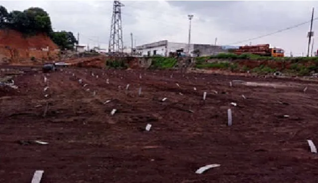
Figure 3 Some vertical drains put in place
The cost of materials, the cost for the purchase of the material, the cost of labour and the overall cost for the construction of drains are shown inannex 2.
The average daily drain production is129 drains/day.
The cost of materials, the cost for the purchase of the material, the cost of labour and the overall cost for the putting in place of the draining layer is shown inannex 3.
That is:
xthe height of the supporting ground (m);
ythe height of the prefabricated vertical drains (m); zthe height of the draining layer (m);
Thus, the objective function shall be expressed as follows:
Min f(x, y, z) = 56 556 011.5 x+ 1 129 701.6 y+79 864 066 z The resulting expression of soil consolidation time is thus as follows:
Working time [t] in (hrs) =101.2 x + 0.5 y + 91.1 z The objective function obtained is:
Constraints defining the formulation of the optimization problem stems from the numerous information gathered from special technical specifications (CCTP), fascicles relating to the secondary access project, the Technical Refill Guide as well as the Technical Guide for the refill of trenches.
According to procedure VRD/SOG/PES/EXE/1185/B, vertical drains should be built under the buttress of standard sectionPK2+500 to PK2+680and under the entry rampPT12 to PT21. The total number of drains to be constructed is2011.The draining network is a mesh of2.5 x 2.5 m2made up of flat drains built at a depth of20m or until refusal when the clay layer comes before.
The platform should be made of Wouri sand layersof a total thickness varying between1m30 and 1m80, thus avoiding preliminary drilling while providing the required carrying capacity.
For vertical drains to function perfectly, a draining surface comprising a pozzolan layer of at least 50 cmshall be built on the working platform.
Knowing the total height of the roadway (from thered line to underlying soil), as well as the thickness of the various layers of the roadway, it would be possible to determine the theoretical height of the platform (Figure 5).
Information ondifferencesTN-transverse profiles project P5 toP10is presented in annex 4.
In the subsequent analyses, we shall work with TN difference and transverse profile projectP6 (TN Difference andProject ≈ 2.99 m)which is the most closer to the average value of1.854 m. From the roadway structure sketch and the cross sectionof the access ramp, one can notice that: theroadway surface is made ofBBwith theoretical thickness e1 = 0.07 m; thebinder courseis
made up ofGBwith theoretical thickness e2 = 0.16 m; theroad
base is made up ofGCwith a theoretical thickness e3 = 0.25 m;
la the subbase course is made up of pozzolan with theoretical thicknesse4 = 0.5 m.
TN Difference and project = Thickness of roadway layers + Thickness of the working platform (ep), Thereby:TN Differenceand project = (e1 + e2+ e3 + e4) + x+zbecauseep = x + z
Considering that:TNDifferenceand project = (TN Difference and project)aver ,we have:
x + z = (TN Difference and project)aver- (0.07 + 0.16 + e3 + e4)
(19)
Or (e3 theoretical – 0.02) ≤ e3 ≤ e3 theoretical 0.23 ≤ e3 ≤ 0.25 (20)
Min f(x, y, z) = 56 556 011.5 x+ 1 129 701.6 y + 79 864 066 z
and (e4 theoretical– 0.02) ≤ e4 ≤ e4 theoretical 0.47 ≤ e4 ≤ 0.50 (21)
(20)+ (21) 0.7 ≤ e3 + e4 ≤ 0.75
0.07 + 0.16 + 0.7 ≤ 0.07 + 0.16 + e3 + e4 ≤ 0.07 + 0.16 + 0.75
0.93 ≤ 0.07 + 0.16 + e3 + e4 ≤ 0.98
2.99 - 0.93 ≥ (TN Difference and Project)aver– (0.07 + 0.16 + e3 + e4) ≥ 2.99 - 0.98
2.06 ≥ (TN Difference and Project)aver– (0.07 + 0.16 + e3 + e4) ≥ 2.01 (22)
(19)in(22) : 2.06 ≥ x + z ≥ 2.01 (C1)
According tofascicle E3 Earthworks – subformation leveland theprocedure for the construction of vertical drains, z ≥ 0.5 (C2)
According to theTechnicalGuide for the backfill and trenches,
Dmax≤ 2/3 z. also, according to Fascicle E3 Earthworks,Dmax≤
½ x.Supposing thatDmax= 50 mm, we find that: 2 Dmax≤ ½ x +
2/3 z 0,1 ≤ ½ x + 2/3 z (C3)
According to theprocedure for the construction of vertical drains, we were able to deduct the following constraints: z ≥ 0.5; 1.30≤ x ≤ 1.80; y ≥ 20;
The maximum depth attained by drains is of about 25 m. Thereby: y ≤ 25;
According to the provisional plan for the execution of the additional project, the construction of drains should be done in7 daysand the duration for the construction of the platform on the North access way should be 9 months. Consequently, the following constraints are derived from relations between the necessary time for the construction of drains (respectively for the construction of the platform) and the duration earmarked for each sub-structure (expressed in hours): 0.5 y ≤ 56 and 101.2 x + 0.5 y + 91.1z ≤ 1 728(C4)
It should be recalled that the platform should be made up of
Wouri sand layers of a total height between1m30 and 1m80 :
1.30 ≤ x ≤ 1.8(C5)
Inequationsy ≤ 25 and x ≤ 1,80are summarized as: x + y ≤ 26.8 (C6)
Inequationsy ≥ 20, x ≥ 1.30 and z ≥ 0.5are summarized as : x + y + z ≥ 21.8; (C7)
Thereby the optimization problem:
Solving The Optimization Problem
The objective function is a minimizing or maximizing type, depending on n variables (x1, x2,…,xn). Theseare satisfactory to
constraints if they are within or at the periphery of an
associated hyper-volume limited by its constraints. To solve a linear programming problem, we could use the graphical method, the big M method, the 2-phases method or the simplex method. The latter is the main tool used to solve linear programmingproblems. It is an iterative algebraic method that helps to find the exact solution to a linear programmingproblem through a limited number of phases.
A general linear programming problem may be expressed as follows: finding n variables valuesxj, j = 1, 2, …, nthat are
satisfactory to m inequations or linear equations (constraints) in the form of:
ai1 x1+ ai2 x2 + … + ainxn bi, i = 1.2,…,m
To solve this problem, we shall use the duality theorem. Let be the initial linear program, referred to as primal,a second linear program, referred to as dualprogram (equivalent and obtained by introducing difference values).The theorem stipulates that: « For any solution relating to the primal and any solution relating to the dual, z, the objective of the primal, shall be lower or equal to w, the objective of the dual. If the primal has anoptimal solution , …, then the dual shall have anoptimal
solution , …, and for these solutions, the primal’s objective shall be equal to the dual’s objective»:
Minimizing f(x, y, z)= 56 556 011.5 x+ 1 129 701.6y +79 864 066 z
Sub-constraints: (- x) + (-z) ≥ (- 2,06) x + z ≥ 2,01
½ x + 2/3 z ≥ 0,1
(- 101,2 x) +(-0,5 y) + (-91,1z) ≥ (- 1 728)
(-x) + (-y) ≥ (- 26,8)
x + y + z ≥ 21,8 z ≥ 0,5 x , y , z ≥ 0
The minimizing function dual’s is therefore:
Maximizing g = – 2.06 s1 + 2.01 s2 + 0.1 s3 – 1728 s4 – 26.8 s5 +
21.8 s6 + 0.5 s7
Constraints: – s1+ s2 + 0.5 s3– 101.2 s4– s5 + s6≤ 56 556 011.5
– 0.5 s4– s5 + s6≤ 1 129 701.6 – s1 + s2 + 0.67 s3 – 65.6 s4 –
s5 + s6 + s7≤79 864 066 s1, s2, s3, s4, s5, s6, s7 ≥ 0
Let’s introduce the following three difference variables u, v, w,we thus obtain an equivalent formulation of the problem:
Maximizing g = – 2.06 s1 + 2.01 s2 + 0.1 s3 – 1728 s4 – 26.8 s5 +
21.8 s6 + 0.5 s7
Constraints:– s1 + s2 + 0.5 s3 – 65.6 s4 – s5 + s6 + u =
6 556 011.5– 0.5 s4 – s5 + s6 + v = 1 129 701.6 – s1 + s2 + 0.67 s3
– 65.6 s4– s5+ s6 + s7 +w =79 864 066
Minimising f(x, y, z) = 56 556 011.5 x+ 1 129 701.6 y +79 864 066 z
underconstraints : x + z ≤ 2.06; x + z ≥ 2.01 ;
0.1 ≤ ½ x + 2/3 z ; 101.2 x + 0.5 y + 91.1z ≤ 1 728 ;
x + y ≤ 26.8 ; x + y + z ≥ 21,8 ;
This formulation makes it easy to express difference variables as affine functions of decision values:
Variables u, v andw are base variables and s1, s2, s3, s4, s5, s6, s7
are out-of-base variables. The basic solution, associated to a dictionary, is obtained by attributing value 0 to all out-of-base variables. The basic solution corresponding to Dictionary 1 shall be therefores1 = s2 = s3 = s4 = s5 = s6 = s7 = 0, giving:u =
56 556 011.5; v = 1 129 701.6; w = 79 864 066; g = 0.
Let’s consider an out-of-base value whose coefficient in the last line of the dictionary is positive. Let’s choose for instance s6 as the base’s entryvariable. s6is increased as from 0, the other
out-of-base values remaining null. Constraints on the increase of s6are as follows:
u≥ 0 56 556 011.5 – s6≥ 0 s6≤ 56 556 011.5
v≥ 0 1 129 701.6 – s6≥ 0 s6≤ 1 129 701.6
w≥ 0 79 864 066 – s6≥ 0 s6≤79 864 066
The most restrictive among these constraints iss6≤
1 129 701.615. Thereby, the exit value of the base is v. Let’s change dictionaries by swapping the roles of s6and v. We shall
use the second equation of dictionary 1 to express s6as
depending on s4, s5, v:
s6= 1 129 701.615 + 0.5 s4 + s5 – v.
Let’s then replace s6 with this expression in the other equations
of the dictionary:
Let’s decide to bring in s2 into the base; we obtain the
following limits on the increase of s2:
u≥ 0 55 426 309.9 – s2≥ 0 s2 ≤ 55 426 309.9
w≥ 0 78 734 364.4 – s2 ≥ 0 s2≤78 734 364.4
The most restrictive of these constraints iss2 ≤ 55 426 309.9.
Therefore, the exit variable of the base is u. The first equation of dictionary 2 is used to express s2against u, s1, s4, v:
s2 = 55 426 309.9 + s1 – u– ½ s3 + 100.7 s4 + v.
s2is then replaced by this expression in the other equations of
the dictionary:
We then decide to include s7 into the base; the following limits
are obtained on the increase ofs7:w ≥ 0 23 308 054.485 – s7 ≥
0 s7≤23 308 054.5
Thereby the exit value of the base shall be w. The third equation of dictionary 3 is used to express s7against w, u, s3, s4:s7 =
23 308 054.485 + 1/3 s3 + 25,5 s4 – 5/3 s5 – w + u.
Then, s7 is replaced by this expression in the other equations of
the dictionary:
According to the duality principle, the optimal solution of primalf * is equal to the optimal solution of dual g,therefore,f * = 147 688 405.35. In addition, the optimal values of variables x, y and z of primal (x*, y*, z*) equate coefficients associated with base variables of dictionary 1. Therefore: x = 1.51; y = 19.79; z = 0.5.
Inconclusion:
Digital authenticationwithMatlab
Results obtained by using the Matlab software are presented inAnnex 7.
Cost Analysis of Soil Consolidation Through Vertical Drains
Real costs for soil consolidation with vertical drains: the case of the North Access Ramp from PT 12 to PT 21.1
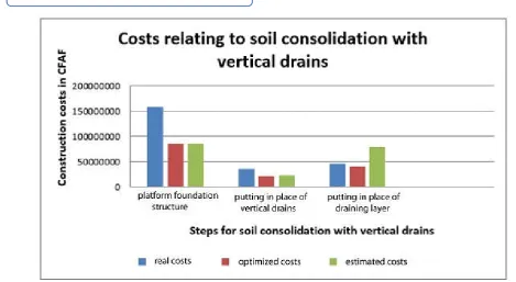
According to the draftsurvey statement of ContractNo. 000428/M/MINMAP/CCPM-AI/2015 for additional works of the project for the construction of the 2nd bridge on the Wouri River, the real overall cost for soil consolidation with vertical drains from PT 12 to PT 21.1 is (CTE): CTR = 158 229 267 + 35
976 960 + 46 682 600 = CFAF240 888 827
Optimal costs for soil consolidation with vertical drains: case of the North Access Ramp from PT12 to PT21.1
Solving the problem manually gave us the following optimum values:
x* = 1.51; y* = 19.79; z* = 0.5
Therefore, the optimal cost for soil consolidation using vertical drains from PT 12 to PT 21.1 (CTO) is: CTO = 85 399 577.4 + 22
356 794.96 + 39 932 033 = CFAF147 688 405.4
Based on the model built earlier and supposing that the thickness of the drainage layer z1 = 1 m, the cost for the putting
f* = 147 688 405.3
x* = 1.51 ; y* = 19.79 ; z* = 0.5
CTE = CFAF 240 888 827
in place of the drainage layer will beCFAF79 864 066. In addition, supposing that the length of drains is y1 = 20 m, the
cost for the construction of drains will beCFAF 22 594 032.3.
Consequently the overall cost for soil consolidation with vertical drains from PT 12 to PT 21.1 (CT1) is as follows:
CT1 = 85 399 577.4 + 22 594 032.3 + 79 864 066 = CFAF187
857 675.7.
Interpretation of results
The optimization of the use of materials has a double impact, in terms of financial resources and time. We have:
An optimal financial gain = CTE- CTO
Financial gain = 240 888 827 - 147 688 405.4
Estimated financial gain = CTE - CT1
Estimated financial gain= 240 888 827 - 187 857 675.7
Gain in time
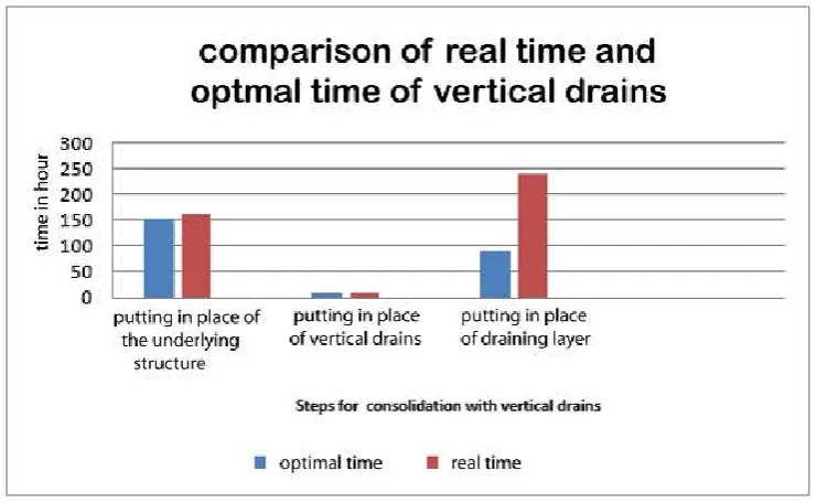
Working time [t] in (h) =101.2 x + 0.5 y + 91.1 z
By replacing x, y and z by x*, y*and z*, we obtain the optimal working time topt:
topt = 101.2 x *
+ 0.5 y* + 91.1 z* x* = 1.51 ; y* = 19.8 ; z* = 0.5
Optimal time for the construction of the basement of the working platform: 151.8hrs
Optimal time for the construction of vertical drains: 10 hrs
Optimal time for the installation of the drainage layer of 1m thickness:
2* (91.1*0.5) = 91.1 hrs
The following information is given by the engineering submission for optimal access ramps:
Construction of the platform foundation: 20 daysthat is160 hrs ;
Installation of the drainage layer of 1m thickness for vertical drains: 30 daysthat’s is240 h ;
According to the history on the production of drains, about 129 drains are put in place daily, whereas 1296 should be constructed, which makes10 days,that is80 hrs.
Effective working time: tE= 160 + 240 + 80 = 480 hrs
From the interpretation of results, there is a reduction in cost of CFAF93 200 421.6 and in deadlines (of 128 hrs).
CONCLUSION
The aim of this study was to optimize the cost of the use of materials during soil consolidation with vertical drains as treatment techniques peculiar to the Wouri working site.
This technique includes the construction of the foundation of the working platform, the putting in place of vertical drains, the installation of the drainage layer. Within the optimization perspective, for each step, we carried out an evaluation of the cost of construction machines, the cost of procuring materials and the cost of labour. These enabled us to draw a mathematical design of a linear system including a function-cost to minimize under constraints provided by technical specifications contained in theprocedures for the execution of vertical drains, theGTRand theCCTP.
Optimum financial gain = CFAF 93 200 421.6
Estimated gain= CFAF 53 031 151.3 CFA
C
T1= CFAF 187 857 675.7
topt= 252.8 hrs
The solution to the design problem was found using the simplex method. Consequently, we obtained a financial gain of54% for the foundation of the platform, 62% for putting the drains in place and85.5% for the drainage layer.
Due to the fact that soil consolidation using vertical drains entails the follow-upofsoil settlement using instruments, we presented results provided by compaction masses, inclinometers and piezometers.
By way of perspectives, we would suggest that a thorough interpretation of curves resulting from the follow-up of settlements be done for a better assessment of the time and quality of soil settlement.Consequently, we would insist on the convergence of results provided by each instrument.
References
Arnaud JUIGNET et al. (2016). Access roads to the second bridge over the Wouri river: reliability improvement due to a test embankment. Journées Nationales de Géotechnique et de Géologie de l’Ingénieur – Nancy
2016.
Chaput D, Pilot G, Queyroi D., (1985) Amélioration des sols de fondation choix des méthodes d'éxécution. Cedex, Paris,57p.
Costet J., Sanglerat G. (1983). Cours pratique de mécanique des sols : plasticité et calcul des tassements. Bolle G. (1997). Compressibilité des sols – tassement des fondations ; (1997).
Didier L., Abba S., (2015). Réalisation des aménagements complémentaires du projet de construction du 2ième
pont sur le Wouri à Douala. Marché
N°000426/M/MINMAP/CCPM-AI/2015, Douala, 230p. Emmanuel KENMOGNE et al (2007. Contribution to the
study of the behaviour of the compressible soils in the Douala basin under uniaxial loading.14ème CRA MSG, Yaoundé, 26-28 Novembre 2007 – 14th ARC SMGE, Yaoundé, 26-28 November 2007.
LCPC, SETRA. (1994)., Remblayage des tranchées et réfection des chaussées. Cedex, Paris, 130p.
LCPC, SETRA., (2000) Réalisation des remblais et des couches de forme fascicule I et II. Cedex, Paris, 211p. Liebherr. Liebherr drain vertical soil.[en ligne]. [consultée le
12.04.16].20p. Disponible sur Internet : http:// www.Special Deep Foundation_compendium Methods and Equipment. Volume II- Google Livres.html
Magnan J.P. (1994). Mesure des amplitudes et vitesses de tassement des remblais sur argiles molles - évolutions récentes. Bulletin de liaison des laboratoires des ponts et chaussées, N° 194.
Martin C., Sadou A. (2013). Conception/réalisation du deuxième pont sur le Wouri à Douala. Marché N°000306/M/MINTP/CCPM-AI/2013, Douala, 46p. Ningbo Honghuan Geotextile Co. LTD. (2013). White PVD
Soft Soil Drainage Material Prefabricated Vertical Drains.[en ligne]. [consultée le 20.04.16]. Disponible sur Internet : http:// www.White PVD Soft Soil Drainage Material Prefabricated Vertical Drains.html
Norme française., (1995) Sols: reconnaissance et essais-Mesures à l'inclinomètre. AFNOR, Paris, 23p.
Portet F., Noel O., Nicaise S., Portillo C., Vermeulen M., (2011) La classification des sols . Aix en provence, 36p. Reiffsteck P., (2007) Traitement des sols. Cedex, Paris, 39p. Rousselot D., Simulation des tassements des sols selon la
théorie de la consolidation de TERZAGHI. Cedex, Orléans, 87p.
Serratrice J.F., Soyez B. (1996). Les essais de gonflement. Bulletin de liaison des laboratoires des ponts et chaussées, N°204. Symposium international sur les aspects géotechniques des argiles molles. Bangkok, 1977.