Development of an adaptable vacuum based orange picking end
effector
Kyusuk You
1, Thomas F. Burks
1*, John K. Schueller
2(1. Department of Agricultural and Biological Engineering, University of Florida, Gainesville, FL 32611, USA; 2. Department of Mechanical and Aerospace Engineering, University of Florida, Gainesville, FL 32611, USA)
Abstract: A prototypical end effector was designed to validate its fruit picking performance focusing on picking success rate and crop quality. The end effector model composed of a central vacuum gripper and four articulate vacuum fingers to enable firm and secure grasping for citrus fruit. Slider-crank mechanism finger structures achieved solid contact between vacuum pad and fruit surface. Instead of stem severing, the fruit was removed by the combined geometrical motion of rotation and pulling. The developed end effector model fulfilled its fruit picking performance with 90.8% of removal rate at 90 degrees (±5°) of the initial approaching angle producing 6~31.5 N and 0.04~1.03 Nm of the detachment force and torque during field assessments.
Keywords: robotic harvesting, vacuum gripper, orange harvesting
Citation: You, K., T. F. Burks,and J. K. Schueller. 2019. Development of an adaptable vacuum based orange picking end effector. Agricultural Engineering International: CIGR Journal, 21(1): 58–66.
1 Introduction
Typically, an end effector is a critical component in
any fruit picking robot which could mimic the human
hand to grip and pick the fruit. One challenging task in
the development of fruit picking end effectors is the
ability to maintain a firm and safe grip on the fruit
throughout the harvesting cycle, because it influences the
market value of the product (Monta et al., 1998).
Therefore, various technologies in the end effector were
proposed in this study to enhance fruit gripping
capability.
For industrial robot grippers, vacuum pads were
commonly used to minimize contact damage to target
objects by regulating to a safe pressure. This approach is
especially useful for fragile objects that require careful
handlings such as glass objects and semiconductor
components. The vacuum grippers also can often adapt to
Received date: 2016-09-08 Accepted date: 2019-01-18
* Corresponding author: Thomas F. Burks, Professor in Agricultural and Biological Engineering Department, University of Florida, Gainesville, FL 32611, USA. Email: [email protected], Tel: 1 352 392-1864.
variations in object dimensions and shapes. Due to their
adaptive functionality and reliable performance, vacuum
grippers were proposed for fruit harvesting by Bullock
(1956), Gerber (1987), Ceres et al. (1998), and Koselka
and Wallach (2006). Although the fruit was grasped by a
suction gripper in these cases, the fruit was picked using a
cutting device, such as scissors or a cutting blade, to
prevent damage to the fruit peel or bruising during
detachment.
In other research, manipulator arm and wrist motions
were utilized to harvest the fruit from the stem similar to
human harvesting approaches. Glover (1975) developed a
rotating auger which was integrated in the center of a
cylindrical tube. Pool and Harrell (1991) developed a
fruit harvesting end effector with a rotating lip and a
collection sock. Ling et al. (2004) developed a robotic
tomato harvester with a linearly actuated movable suction
cup which extended to grasp the fruit and then retracted
to separate the selected fruit from other nearby fruits.
Four articulated gripping fingers then grasped the
separated fruit and the fruit was harvested through a
pulling action executed by the manipulator. In most cases,
servo-control the manipulator to the target fruit position.
Flood (2006) designed a three-finger robotic orange
harvesting end effector which relied on developing
sufficient gripping forces between the fruit and end
effector to accommodate the detachment forces. This
gripper incorporated a machine vision camera in the palm
of the hand. The validation tests were performed using a
7-DOF commercial ready manipulator which employed a
snap-twist-pull harvesting technique. The results showed
very low damage rates. The result of the articulated
harvesting motions was measured using a 6-DOF sensor
which measured the forces and torques imparted to the
fruit during harvest.
To maintain an acceptable grasp on the fruit during
picking by articulated motion, a vacuum-based gripper
must be improved over earlier works. Mantriota proposed
a mathematical gripping model for a set of multiple
square shaped suction cups (2007a), for a single square
shaped suction pad (2007b), and for a single circular
suction pad (2011). In those studies, he defined the axial
and tangential forces of contact between suction pad and
object, and its static friction coefficient. Bahr et al. (1996),
Nishi and Miyagi (1995), Liu et al. (2006), Novotny and
Horak (2009) simulated and analyzed the deformation of
suction pads under shear force, pulling force and moment
as an elastic model, which were used in a wall climbing
robot. Based on the definition of suction force,
multiplying the vacuum pressure by the active area of
vacuum pad, a variation of physical properties of vacuum
pad was studied.
One of the common challenges faced in prior research
using vacuum-based grippers was to maintain the grip on
fruit during the entire picking cycle. In natural crop
settings, other fruit located nearby (fruit often is located
in clusters), leaves, and adjacent branches can create
obstructions, which makes it difficult for the gripper to
separate and grasp an individual fruit. In addition, forces
and torques induced on the fruit during the harvesting
motions can tend to pry the fruit off the suction cup
which can break the vacuum seal and causes harvest
failure. You (2015) designed an orange picking vacuum
gripper using a central linearly actuated vacuum plunger,
the initial fruit separator, and a static configuration of
four small circumferential vacuum pads, the
multi-directional gripper. During field assessments, the
developed model carried out up to 90% of removal rate
for successfully separated oranges (Washington Navel)
within 120~150 degree of end effector’s initial
approaching angel to fruit. However, the end effector
approached to the fruit and separated it from its cluster
successfully for only 55% of fruits. And it was also over
served that the position fixed multi-directional grippers
loosed their vacuum during fruit picking because of
various fruit size and shape.
Therefore, the objective of this study was to design a
more robust end effector that can not only remove the
fruit in higher removal rate, but also be able to pick up
without damage. Instead of the finger-based end effector
model, a vacuum-based gripper was developed in this
study to achieve the proposed goal, along with its
pneumatic control system. The new end effector concept
was designed, 3D modeled, fabricated, and tested under
laboratory and field conditions.
2 Materials and methods
2.1 Design study of end effector
2.1.1 End effector structures
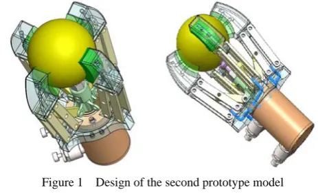
To improve fruit grasping performance, slider-crank
mechanism linkages were utilized as the gripping finger
of the end effector model, each gripping finger’s structure
were clenched and released by 50 mm stoke of a single
Pancake® cylinder (I121-XV, Fabco Air Inc. Gainesville,
FL). It was found from the previous developed model
(You, 2015) that longer retracting distance (125 mm)
caused to fail fruit retrieval. A center vacuum socket and
a manifold integrated end effector base were custom
designed to simplify the air hose lines (Figure 3).
Considering the dimensional properties of Washington
Navels, described in the experimental method and results,
the four fingers were designed to be expanded up to
120 mm of outer circumferential diameter by 50 mm of
linear movement of the central cylinder. Vacuum
passages and ports integrated into the gripping fingers
provided vacuum pressure to the end fingers. And
polychloroprene foam was padded at each end finger to
prevent the vacuum leak during grasping fruit. Each
structural element was manufactured by 3D printing
that would be required to machine each component by
conventional manufacturing methods. The central
vacuum bellows had an outer diameter of 14.5 mm and
1.5 folds (Model: FSGA 14 M5-AG, Schmalz Vacuum
Technology Ltd., Germany).
Figure 1 Design of the second prototype model
2.1.2 Vacuum system
Six ejector modules (Model, SMC Pneumatics Co.
Japan) generated the vacuum pressure for each vacuum
pad. Each of the four fingers used a single ejector module,
while a double ejector module was used for the central
vacuum bellows to create a higher pulling force. Each
ejector module consisted of a vacuum valve unit
(ZX1-VJ114-Y-6LZB), an ejector assembly unit
(ZX1-W071), and a vacuum pressure switch unit
(ZSE3-0X-21CL-Q). The ejector module could generate
–84 kPa of maximum vacuum pressure, with a minimum
of 10 L min-1 suction flow, using a maximum of 0.7 MPa
of primary air pressure.
Considering the diameter of vacuum pads, four
electrical pressure regulators (Model: ITV1030s, 200 L
min-1 of max flow rate, SMC Pneumatics Inc. Japan)
were adopted in vacuum unit of individual gripping finger
and one regulator (Model: ITV 3030, 5000 L min-1 of
max flow rate, SMC Pneumatics Inc. Japan) was
equipped to the central vacuum unit. Both regulators
could adjust output air pressure up to 0.5 MPa, with
1 MPa input air by analogue signal. Output air pressure
from each regulator was controlled by Labview Virtual
Interface (NI Inc. Austin TX) and two data acquisition
devices (Model: MyDAQ ECEN 2250, NI Inc, Austin
TX) and a PCI slot I/O board (NI Inc. Austin, TX). DAQ
devices received twelve analog inputs within 0~5 V from
air pressure vacuum sensors (Model: ZSE40-01-22L,
SMC Pneumatics Inc. Japan) to record current pressures.
Vacuum pressure of each vacuum unit was maintained
within –65 kPa ±10% by the NPN switch control logic of
Labview.
PLC unit (Model: Allen Bradley Micrologix 1200,
Rockwell Automation Inc. Milwaukee, WI) managed the
soleniod valves connected to the the linear actuator and
regulatorse. Figure 2 shows the wiring diagram between
Labview and the pneumatic components.
Figure 2 Pneumatic components and communication diagram
2.1.3 Pneumatic systems
The compressed air (827 kPa) was switched by a
heavy duty solenoid valve to supply from the air
compressor to the air manifold (1X3 Aluminum casted
manifold). The air manifold distributed air flow to the
linear actuator and regulators for the central vacuum units
and finger vacuum units. A manual regulator adjusted the
supplied air pressure to the linear actuator and a 5-port
3-way directional solenoid valve controlled
stroke/retraction of the linear actuator (Pancake® air
cylinder, FabcoAir Inc. Gainesville, FL). In the previous
prototype model (You, 2015), it was found that the
excessive stroking speed moved the target fruit from its
original position and rapid retraction led to the drop the
fruit from the central vacuum bellows. Therefore, two
flow control valves were equipped at the both ports of the
linear actuator.
2.2 Experimental methods
To guide the end effector design, dimensional and
physical properties of the Washington Navels (Citrus
sinensis cv. Navel) were inspected at the research field of
the Plant Science Research and Education Unit (PSREU)
of the University of Florida (Citra, FL). The fruit
detachment force and torque of the prototype end effector
was measured to determine the air pressure supplied to
pneumatic and vacuum systems at the indoor Robot and
Florida (Gainesville, FL). The fruit picking performance
was also evaluated throughout field assessments at the
research grove of the PSREU of the University of Florida.
2.2.1 Dimensional properties and straight-line
detachment forces
The dimensional properties of Navels were measured
at the research field (Citra, FL) from 10 a.m. to 2 p.m. on
October 25, 2014. These measurements provided a
statistical estimate of the mean fruit size and variability.
Longitudinal, lateral diameter and weight were measured
for 240 arbitrarily picked fruits using Vernier Calipers
and a compact weight scale. Eccentricity and oblateness,
the parametric value, were calculated. The purpose of
these measurements was to assist in designing the
mechanical clearance in between finger contact points
and thus the linkage lengths, select padding material for
the fingertips to ensure enough compliance to
accommodate the variability in fruit size, and then to
determine the friction coefficient for the pad to fruit
interface.
Straight-line fruit detachment forces were measured
about 35 mm of pulling distance three different pulling
angles, 90, 120 and 150 degrees using a portable force
gauge concurrently with dimensional property
measurements. The pulling distance represented the
stroking length of the linear actuator and the pulling angle
represented the initial approaching angle of the end
effector. The test was repeated for 20 fruit per each
pulling angles. These measurements established a
vacuum pressure working range required for the central
vacuum bellows to retract the fruit.
2.2.2 Measurement of fruit detachment force and torque
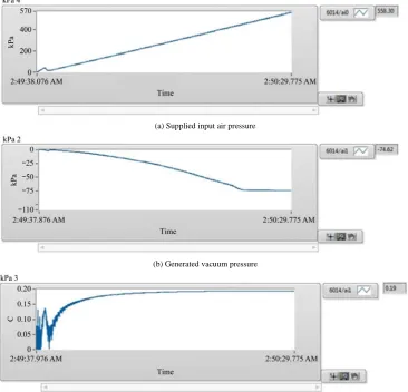
Prior to the fruit detachment force and torque tests,
the coefficient of the transfer function between the supply
input pressure and the generated vacuum pressure in the
ejector module was found to be about 0.2 (Figure 3)
throughout calibration test. The coefficient tended to
increase up to 0.2 within the range of vacuum pressure
from zero to –50 kPa, and over –50 kPa of vacuum
pressure the coefficient maintains at 0.2.
(a) Supplied input air pressure
(b) Generated vacuum pressure
(c) Coefficient of linear transfer function between supplied pressure and generated vacuum pressure
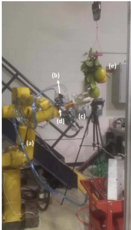
Forty Washington Navels collected from the research
grove of PSREU were used in this measurement test.
Each sample consisted of a branch segment that included
branch, fruit, and leaves. Collected specimens were stored
in a refrigerator at 10ºC for 48 hours before testing.
Before the experiments, specimens were allowed to
equilibrate at room temperature for approximately one
hour and dry to eliminate moisture on their surface. Fruit
cluster specimens were suspended by their supporting
branches to a hoist on the overhead crane in the lab
(Figure 4).
(a) 6 DOF manipulator (b) Ejector modules (c) end effector (d) force/torque sensor (e) sample fruits in a cluster
Figure 4 Fruit detachment force and torque measurements
The end effector was mounted on 6-DOF ARC Mate®
robot manipulator. And a six-axis force/torque transducer
(Mini 45 model, ATI Industrial Automation, Apex NC)
was installed in the prototype end effector to measure the
required force and torque to detach the fruit from its
branch. A 6014 PCI DAQ board (NI Co. in Austin, TX)
and Labview collected z-axis force and torque data in the
form of an analog voltage signal. A Chebyshev analog
low pass filter was adopted to eliminate periodic noise in
transmitted signals. The initial fruit pulling angle was
determined from results of the fruit separation force
measurement test: 90-120 degree from the collinear axis
of fruit stem. The air compressor discharged 500 kPa
(±10%) of air to the linear actuator (400 N for stroke and
320 N for retraction of theoretical force).
Figure 5 shows the fruit picking operation sequences.
All pneumatic valves and switches are activated by a start
toggle switch of PLC unit (MicroLogix 1200, Rockwell
Automation Inc. Milwaukee, WI). The central linear
actuator strokes the central vacuum gripper to hold a
target fruit and separate it from surrounding fruits. The
isolated fruit is grasped by four vacuum gripping fingers
and removed from its tree by ±360 degree of rotation and
linear pulling back. Vacuum sensors keep monitoring real
time vacuum pressure during the motion of pulling back
which determines the success of picking. The cycle time
goal was 4.5 seconds, which is 2.5 second longer than
Flood’s model (Flood, 2006), due to the time required to
measure the force/torque during picking and to prevent
damages on the plastic finger structures.
Figure 5 Fruit picking operation scheme
The ejector modules were controlled independently to
prevent pressure drop and insufficient suction flow in the
ejector module with increased distance from the primary
port. The vacuum pressure was regulated independently
by adjusting the primary air pressure.
The end effector was determined to pick up fruit at
either 90 or 120 degrees based on the results of fruit
model (You, 2015) and measurements of the initial fruit
separating force conducted in this study.
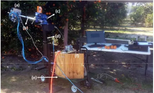
2.2.3 Fruit picking performance evaluation
A complimentary mobile manipulating system
(Figure 6) was arranged to position the end effector near
the fruit and to provide the end effector’s rotation to pick
fruit, in lieu of the ARC Mate® robot manipulator used in
the laboratory test. The mobile manipulating system
consisted of a double cylinder type pneumatic rotary
actuator (DRQD-20-360, Festo Pneumatics Co. Japan), a
custom designed linear expandable linkage, a multi
directional swivel vise (Central Forge Co. Stafford
England), an electrical telescopic lift and a flatbed garden
cart (YTL International Inc. Cerritos CA). The fruit was
picked using a ±360 degree of repeated rotation. The test
system consisted of the end effector, the mobile
manipulating system, a pneumatic control box, a desktop
computer and a commercial 76 L and 1.4 MPa air
compressor. A PLC unit controlled pneumatic valves,
pressure regulators and vacuum ejector modules. Desktop
computer was prepared to monitor the end effector’s
operation stage in ladder logics and to collect sensed
pressure and vacuum data though PCI DAQ board and
Labview solution.
(a) prototype end effector (b) 1 DOF expandable linkage (c) 2 DOF swivel vise (d) electrical telescopic lift (e) garden flatbed cart (f) system controller box (g) desktop computer
Figure 6 Fruit picking performance test set
To optimize the amount of air flow consumed by the
ejector modules, four different vacuum control modes
were adopted to during the fruit picking operation. In the
first mode (Mode 1), the fruit was grasped by the central
vacuum bellows and polychloroprene padded fingers,
with the vacuum pressure activated during the rotation
procedure. In the second mode (Mode 2), the vacuum
pressure in the gripping fingers was deactivated, so that
the fruit was held by the central vacuum bellows and
frictional resistance of fingers. The third grasping mode
(Mode 3) deactivated the central vacuum gripper while
activating the finger vacuum grippers. The fourth
grasping mode (Mode 4) was executed by only closing
the padded fingers without vacuum gripping by either the
central or finger vacuum pads. Each experimental case
was conducted for ten fruits in each of the
three-dimensional groups, A=60~75 mm, B=75~90 mm,
and C>90 mm.
3 Results and discussion
3.1 Dimensional properties and straight-line
detachment forces
Idealized fruit grasping would occur for a spherical
shaped object. However, a practical fruit model is a
spheroid model, close to a sphere but not perfect. Since
the gripping fingers attached to the fruit surface using
planar contact, the radius of the fruit surface should be
evaluated for firmness of grip. Table 1 shows the
dimensional properties of fruits by longitudinal and
lateral diameter and the parametric value of eccentricity.
The Gaussian curvature was calculated to characterize the
fruit surface which decided grasping performance of the
suction bellow.
Table 1 Dimensional properties of sample fruit, n=240
Long. Dia. Lat. Dia. Eccentricity Min. K Max. K [a] Minimum (Min) 61.1 63.0 0.772 0.000356 0.000364 Maximum (Max) 99.5 106.0 0.565 0.001008 0.000168 Mean 84.7 89.9 0.321 0.000521 0.000623 Standard Deviation
(STDV) 9.622 11.055 0.126 0.000154 0.001112 Note: [a] Gaussian curvature (mm).
Table 2 shows the maximum, minimum, mean, and
standard deviation of a straight-line detachment force
measured by pulling the fruit 35 mm back from its
original position. The angle of pulling had a ±5° error
range due to the difficulty of identifying the fruit stem’s
position among adjacent fruit. Fruit pulling within 90
degree required about 4±1 N detachment force to pick up
the fruit illustrating the minimum straight-line
detachment force among three intended angles. Higher
detachment forces were usually inspected in higher
Table 2 Straight-line detachment force for given pulling angle,
n=240
Force (N) 90 degrees 120 degrees 150 degrees
Min 2.3 10.7 14.1 Max 5.2 18 26.8 Mean 4 14.4 20.4 STDV 1.003 2.088 4.261 Note: * Three angles were between the axis of central cylinder and fruit dangling axis. ** Tests for each angle were repeated 20 times.
3.2 Measurement of fruit picking force and torque
The two graphs in Figure 7 illustrate processed signal
of force and torque along z-axis for one cycle of fruit
picking. At the instance of detachment of stem, the end
effector’s linear force and rotational torque reach to the
maximum level at the same time. In this study, the peak
force and torque value at the instance of fruit picking are
defined as fruit detachment force and torque. Table 3
shows the statistics of fruit detachment force and torque
for 20 trials with Washington Navels. The proportional
gains of the force and torque sensor were set as -50.5 and
6.25, which were acquired by manual calibration using a
Dillon Quantrol compact force gauge, on the 10th of
February in 2015. The average value of fruit detachment
force and torque was recorded at 16.70 N and 0.54 Nm.
(a) Detachment force
(b) Torque
Figure 7 Measurement of fruit detachment force and torque
Table 3 Statistics of fruit detachment force and torque
Model Sample size Mean STDEV Min Max Max Force (N) 20 16.70 6.5798 6.00 31.50 Max Torque (Nm) 20 0.54 0.2612 0.04 1.03
3.3 Fruit picking performance evaluation
The performance test showed that the end effector
achieved 90.8% of fruit removal rate and 5% of in-stem
removal rate with 90° of initial approaching angle and
67.5% fruit removal rate and a 3.33% in-stem removal
rate with 120° of initial approaching angle for
Washington Navels (n=240). No visible physical damage
was found on the fruit surface except for peel plugging at
the stem during separation. The fruit removal rate was
reported with a mean diameter of samples and the
percentage at which stems remained intact on the
peduncle, shown together in Table 4.
The test with 90° of the approaching angle showed
consistent fruit removal rate except for fruits in group C
using mode 4. At both approaching angles, the end
effector achieved 90% and higher removal rate with all
vacuum control modes for fruits in group A in which 0%
Table 4 Results of fruit picking performance test
90° approach angle
Mode #1 ** Mode #2 ** Mode #3 ** Mode #4 **
Group * A B C A B C A B C A B C
Total Removal rate [a] 100 100 80 100 100 90 100 80 90 100 90 60 90.8
Mean [b] 70.7 80.4 95.2 71.8 82.4 97.6 69.2 80.1 97.6 68.1 78.7 101 82.8 STDV [b] 3.58 7.21 3.48 2.82 5.54 4.66 2.7 5.48 4.92 3.04 4.88 2.83 8.42 Stem rate [c] 0 0 0 0 20 0 20 0 10 0 10 0 5 Length [d] 0 0 0 0 17.2 0 20.5 0 14 0 18.6 0 18
120° approach angle
Removal rate 100 90 70 100 70 40 90 60 10 100 40 40 67.5 Mean 68.2 78.6 98.1 71.9 80.2 95.6 70.8 79.1 94.1 71.5 80.3 97.6 82.2 STDV 2.41 4.85 6.47 5.24 5.69 3.11 4.48 6.16 7.57 3.79 6.48 4.49 7.05 Stem rate 0 10 0 10 0 10 0 0 10 0 0 0 3.33 Length 0 10.5 0 12 0 15.1 0 0 10.7 0 0 0 12.1 Note: * Each group included 10 sample fruits; ** Each vacuum control mode described in Section 2.2.4; [a] Fruit removal rate (number of picked fruit/total trials) (%);[b] Mean diameter/Standard deviation for samples (mm); [c] Fruit removal rate with stem (number of picked fruit with stem/total trials) (%);[d] Length of belonged stem with picked fruit (mm).
4 Conclusions
The end effector’s fruit detachment force range
reported in this study, from 6 to 31.5 N, appeared similar
to the results reported by Flood (2006), from 7 to 32 N.
Differences can be attributed to seasonal or variety
variability, or possibly from late winter frost damages at
the fruit peduncle union.
The end effector picked up 90.8% of fruits
successfully at the 90 degree of the approach angle. In
particular, fruit picking using the second vacuum control
mode achieved over 95% of fruit removal rate. The
reported end effector demonstrated a significant
improvement in harvesting efficiency over the first
prototype model (You, 2015) achieving a higher fruit
detachment success rate with lower fruit detachment
force. Additionally, to further improve the reliably of
grasping fruits of various sizes, the geometrical position
of the vacuum pad should be more adjustable to the
curvature of the contact area on the fruit surface. Also, it
may be necessary to utilize vacuum ejector modules that
can generate a higher vacuum pressure for the end
effector to harvest fruits when the approach angle is
larger than 120 degrees.
References
Bahr, B., Y. Li, and M. Najafi. 1996. Design and suction cup analysis of a wall climbing robot. Computers and Electrical
Engineering, 22(3): 193–209.
Bullock, G. E. 1956. Fruit picking apparatus. U.S. Patent No. US 2,775,088 A.
Ceres, R., J. L. Pons, A. R. Jimenez, J. M. Martin, and L. Calderon. 1998. Agribot: A robot for aided fruit harvesting. Industrial Robot, 25(5): 337–346.
Dean, E. A. 1979. Atmospheric effects on the speed of sound. Journal of the Acoustical Society of America, 72(2): 60. https://apps.dtic.mil/dtic/tr/fulltext/u2/a076060.pdf.
Flood, S. J. 2006. Design of a robotic citrus harvesting end effector and force control model using physical properties and harvesting motion tests. Ph.D. diss., Agricultural and Biological Engineering, University of Florida.
Gerber, C. E. 1987. Fruit harvesting machine. U.S. Patent No. US 4,674,265 A.
Glover, G. M. 1975. Fruit picking apparatus. U.S. Patent No. US 3,925,973 A.
Hannan, M. W., and T. F. Burks. 2004. Current developments in automated citrus harvesting. ASAE Paper No. 043087. ON, Canada: ASAE.
http://citrusmh.ifas.ufl.edu/pdf/db/Hannah04ASAE043087.pdf Koselka, H., and B. Wallach. 2006. Agricultural robot system and
method. Patent No. WO 200,606,3314 A2.
Li, Z., and S. Sastry. 1988. Task-oriented optimal grasping by multifingered robot hands. Journal of Robotics and Automation. IEEE, 4(1): 32–44.
https://ieeexplore.ieee.org/iel1/56/50/00000769.pdf.
Ling, P. P., R. Ehsani, K. C. Ting, Y. T. Chi, N. Ramalingam, M. H. Klingman, and C. Draper. 2004. Sensing and end-effector for a robotic tomato harvester. ASAE Paper No. 043088. ON, Canada: ASAE.
spherical fruit harvesting robot, In 2007 IEEE International Conference on Automation and Logistics, 258-262. Jinan, China., 08 October 2007. DOI: 10.1109/ICAL.2007.4338567. Liu, J., K. Tanaka, L. M. Bao, and I. Yamaura. 2006. Analytical
modelling of suction cups used for window-cleaning robots. Vacuum, 80(6): 593–598.
Mantriota, G. 2007a. Optimal grasp of vacuum grippers with multiple suction cups. Mechanism and Machine Theory, 42(1): 18–33.
Mantriota, G. 2007b. Theoretical model of the grasp with vacuum gripper. Mechanism and Machine Theory, 42(1): 2–17. Mantriota, G., and A. Messina. 2011. Theoretical and experimental
study of the performance of flat suction cups in the presence of tangential loads. Mechanism and Machine Theory, 46(5): 607–617.
Monta, M., N. Kondo, and K. C. Ting. 1998. End-effector for
tomato harvesting robot. Artificial Intelligence Review, 12:11-25
Nishi, A., and H. Miyagi. 1995. Mechanism and control of propeller type wall-climbing robot. In Proceedings of IEEE/RSJ International Conference on Intelligent Robots and Systems, 669-677. Munich, Germany, 12-16 September 1994. Novotny, Fr., and M. Horak. 2009. Computer modeling of suction
cups used for window cleaning robot and automatic handling of glass sheets. The Modern Machinery Science Journal, June 2009: 113–116.
Pool, T. A., and R. C. Harrell. 1991. An end-effector for robotic removal of citrus from the tree. Transactions of the ASAE, 34(2): 373–378.


![Parliament's role in prospering European integration and the relations between The Republic of Kosov and The Republic of Serbia : [presentation given on September 6, 2011]](data:image/gif;base64,R0lGODlhAQABAIAAAP///wAAACH5BAEAAAAALAAAAAABAAEAAAICRAEAOw==)