Time-based Updates in OpenFlow:
A Proposed Extension to the OpenFlow Protocol
Tal Mizrahi, Yoram Moses
∗Department of Electrical Engineering
Technion — Israel Institute of Technology
[email protected], [email protected]
July 7, 2013
Abstract
Software Defined Networking (SDN) defines a network architecture in which the control plane is managed by a logically centralized controller, and thus con-figuration updates occur frequently. We have recently introduced an approach that uses time-based configuration updates, allowing to simplify complex update pro-cedures and to minimize transient effects caused by configuration changes. This paper proposes an extension to the OpenFlow Protocol that allows time-triggered configuration updates.
1
Introduction
Software Defined Networking (SDN) defines a clear distinction between the data plane and the control plane; on the data plane, forwarding decisions are taken locally at each switch in the network, while the control plane is managed by a logically-centralized controller, overcoming the need for complicated distributed control protocols and pro-viding network operators with powerful and efficient tools to control the data plane.
The centralized approach in SDN introduces various challenges in terms of per-formance and consistency. The controller is required to routinely perform frequent network configuration updates. Thus, update procedures must be as simple as pos-sible, avoiding complex and stateful processes in the controller. Moreover, the con-troller must take care to minimize network anomalies during update procedures, such as packet drops or misroutes caused by temporary inconsistencies.
Time-based configuration [1] can be a useful tool that enables an entire class of coordinated and scheduled configuration procedures. Time-triggered configuration al-lows coordinated network updates in multiple devices; a controller can invoke a coordi-nated configuration change by sending update messages to multiple switches with the same scheduled execution time. A controller can also invoke a time-based sequence
of updates by sendingnupdate messages with ndifferent update times,T1,T2, ...,Tn,
determining the order in which the corresponding operations are executed.
This paper introduces time-based updates in OpenFlow [2, 3]. Configuration in OpenFlow is performed on two different planes; the control plane is managed by a
controllerusing the OpenFlow wire protocol [3], whereas the management plane is managed by aconfiguration pointusing the OpenFlow Management and Configuration Protocol (OF CONFIG) [4]. The latter is typically used for initializing basic configu-ration in the network, whereas the former is used for routine and frequent configuconfigu-ration updates.
This paper defines an extension to the OpenFlow wire protocol that allows the use of time-triggered configuration updates. This extension is implemented using a Type/Length/Value (TLV) field that can be included in any of the existing OpenFlow messages.
Since the OF CONFIG Protocol uses NETCONF [5] messages, the NETCONF time capability we defined in [6] can be used to provide similar functionality in OF CONFIG.
The rest of this paper is organized as follows. Section 2 describes a few basic scenarios of time-based configuration updates. In Section 3 we present a high-level overview of our proposal for time-triggered updates in OpenFlow. In Section 4 we present a proposal for an OpenFlow extension that allows generic TLVs, and finally Section 5 introduces the OpenFlow time extension.
2
Time-based Update Scenarios
This section presents three basic scenarios of time-based updates in OpenFlow.
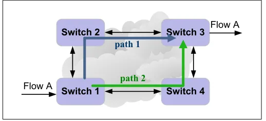
Example 1.
Consider a network with four switches (Figure 1). Flow A is forwarded through path 1, and we consider a scenario in which the controller updates the route from path 1 to path 2 .
Switch 2
Switch 1
Switch 3
Switch 4
Flow A
Flow A
path 1
path 2
Without using time: The controller performs two steps; first the controller con-figures the flow table in Switch 4 to forward traffic from Flow A through path 2, and then it configures Switch 1 with the new path. Obviously if Switch 1 is updated be-fore Switch 4, traffic may temporarily be mis-routed or dropped. Thus, the controller must wait for an acknowledgment from Switch 4 about completing the update before sending the update message to Switch 1.
Time-based Update: The controller sends two time-based update messages to Switches 1 and 4. Switch 4 is scheduled to modify its configuration at timeT, and Switch 1 atT+∆. The time-based update guarantees the update order while simplify-ing the controller’s procedure.
Example 2.
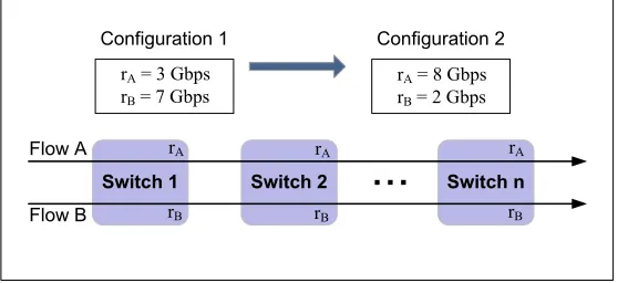
In this example two flows, A and B, are forwarded through a common path that has a bandwidth of 10Gbps, and thus the combined bandwidth of the two flows cannot exceed 10 Gbps. A metering mechanism is used in thenswitches to limit the rates of Flow A and Flow B to 3Gbpsand 7Gbps, respectively. The goal in this scenario is to reconfigure the metering tables in Switches 1,2, . . . ,nso that the rate limits of flows A and B are 8Gbpsand 2Gbps, respectively.
Flow A
Switch 1 Switch 2 Switch n
Flow B
rA
Configuration 1
rA= 3 Gbps rB= 7 Gbps
Configuration 2
rA= 8 Gbps rB= 2 Gbps
rA rA
rB rB rB
Figure 2: Metering Update
Without using time:The controller reconfigures Switches 1,2, . . . ,nwith the new configuration. Since thenupdates do not occur simultaneously, this procedure yields a transition period during which some of the switches operate according to Configura-tion 1, while other switches operate according to ConfiguraConfigura-tion 2. During this transi-tion period Flow A is effectively limited to 3Gbpsand Flow B is effectively limited to 2Gbps, reducing the total bandwidth of the two flows to 5Gbps.
Example 3.
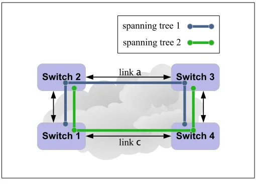
In this example, the controller implements the Spanning Tree Protocol (STP) by di-rectly configuring the switches’ ports.1 The network is configured according to span-ning tree 1 (Figure 3), and then the controller reconfigures the network to spanspan-ning tree 2.
Switch 2
Switch 1
spanning tree 1
Switch 3
Switch 4
spanning tree 2
link a
link c
Figure 3: Spanning Tree Update
Without using time:The controller updates the network by a series of updates to the four switches. These updates essentially disable linka, and enable linkc. The order in which the updates are performed is cardinal; if linkcis enabled first a temporary network loop is created. On the other hand, disabling linkafirst temporarily breaks the connectivity between two subsets of the switches, and more importantly may also disconnect the controller from some of the switches.
Time-based Update: The controller invokes the configuration change, such that all updates are scheduled at timeT. The switches update their configuration at timeT, and after a short transition period the network is configured with the new spanning tree. The short transition period has two causes: the switch clocks may not be perfectly synchronized, and packets that are en-route during the configuration change may be dropped or forwarded incorrectly. The time-based update in this case reduces the tran-sition period, and prevents the potential problem of disconnecting the controller from some of the switches.
1The OpenFlow spec explicitly specifies that the controller can implement the spanning tree protocol
3
Using Time in OpenFlow
Overview
The extension defined in this document allows to add a time field to any existing Open-Flow message.
Controller-to-switch messages: When a message includes a time field, this field indicates the time at which the switch is scheduled to perform the operation specified in the OpenFlow message. For example (see Figure 4): if anOFPT_PORT_MODmessage is sent with a time field (Ts), it specifies the time at which the switch should perform
the port attribute changes specified in the message.
switch
Time controller
Ts OpenFlow
Message (with Ts)
Switch executes operation at Ts.
Figure 4: Controller to Switch Message
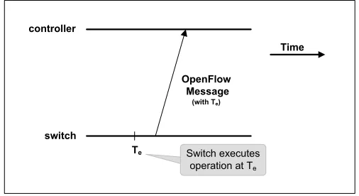
Switch-to-controller message:When a message includes a time field, it indicates the time of the event or operation that triggered this message. For example (see Fig-ure 5), if anOFPT_FLOW_REMOVEDmessage includes a time field (Te), it specifies the
time at which the corresponding flow was removed from the switch’s flow table.
switch
Time controller
Te Switch executes operation at Te OpenFlow
Message (with Te)
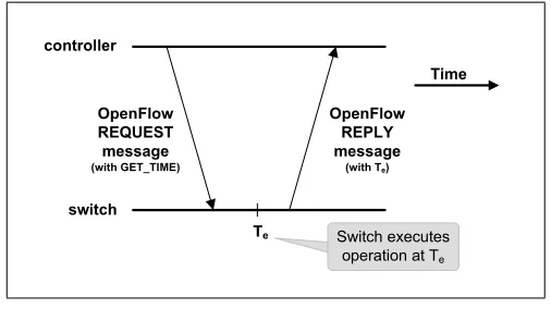
Request/reply handshakes: When the controller sends a request message, it may include the GET_TIME flag, indicating that the corresponding reply should include the time field. For example (see Figure 6), if the controller sends an
OFPT_MULTIPART_REQUESTwith a request for flow statistics and with theGET_TIME
flag, the switch includes the time field (Te) in its reply, specifying when the statistics
were sampled.
switch
Time controller
Te OpenFlow
REQUEST message (with GET_TIME)
Switch executes operation at Te
OpenFlow REPLY message (with Te)
Figure 6: Controller to Switch Message with GET TIME
The Time TLV
The proposed extension allows to add the time field to all existing and future OpenFlow messages by using a time TLV.
Type/Length/Value (TLV) fields allow a flexible method to add information with potentially variable or unknown format and length. Currently, OpenFlow [3] does not support generic TLVs. Although future versions of the protocol may support generic TLVs, the approach proposed here enables using TLVs in all message types.
Hence, we define the time TLV in two steps: first, in Section 4 we define a generic mechanism that allows to add TLVs to all existing OpenFlow messages, and second, in Section 5 we define the Time TLV.
Synchronization Aspects
The time capability defined in this document requires switches to maintain clocks. It is assumed that clocks are synchronized by a method that is outside the scope of this document.
typically be predicted with a high level of accuracy, the execution time of a software module may be variable and hard to predict. A configuration update typically involves the switch’s software, thus affecting how accurately the operation can be scheduled.
Since a switch does not perform configuration changes instantaneously, the pro-cessing time of required operations should not be overlooked; in the context of the extension described in this paper the scheduled time and execution time always refer to the completion time of the relevant operation.
4
Generic Experimenter TLV Extension
This document describes an ONF extension to OpenFlow version 1.3.x / 1.4 that al-lows a generic experimenter TLV-based extension to all existing OpenFlow message types. This section is also submitted as an extension proposal to the ONF Extensibility Working Group.
How It Works
Type/Length/Value (TLV) fields allow a flexible method to add information with po-tentially variable or unknown format and length. Thus, TLVs can provide a useful tool for experimentation.
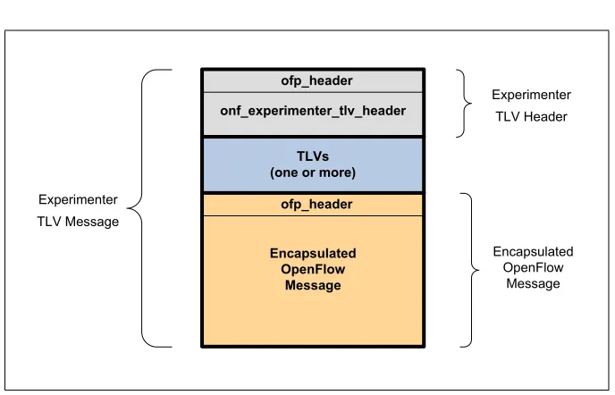
This extension allows to add TLV-based extensions to any existing and future Open-Flow message. This is done by encapsulating the standard OpenOpen-Flow message in the “Experimenter TLV Message” defined in this document, as shown in Figure 7.
The experimenter TLV message format is illustrated in Figure 7. The message is comprised of the Experimenter message header, followed by one or more TLV fields, and finally the encapsulated OpenFlow message, which can be any type of OpenFlow message.
The experimenter TLV approach is a generic mechanism that can add extensions to existing OpenFlow messages without changing their format.
Experimenter ID
The experimenter ID of this extension is:TBD-TLV-Extension-ID
Experimenter TLV Message
Experimenter TLV Header
This extension defines the following experimenter types :
/* Message types */ enum onf_exp_type {
/* Experimenter TLV Message. */ ONF_TLV_EXTENSION = 0x3210, };
onf_experimenter_tlv_header
TLVs (one or more)
Encapsulated OpenFlow
Message ofp_header ofp_header
Experimenter
TLV Message
Experimenter TLV Header
Encapsulated OpenFlow
Message
Figure 7: Experimenter TLV Message Format
/* Experimenter TLV header */ struct onf_experimenter_tlv_header {
struct ofp_header header; /* Type OFPT_EXPERIMENTER. */
uint32_t experimenter; /* TBD-TLV-Extension-ID */
uint32_t exp_type; /* ONF_TLV_EXTENSION */
uint16_t tlv_length; /* Total length of the (one or more) TLV fields */
uint8_t pad[6]; /* 64-bit alignment */
};
OFP_ASSERT(sizeof(struct ofp_experimenter_header) == 24);
The experimenter TLV header is followed by one or more TLV.
TLV Fields
The TLV fields defined in this document have the following format:
/* TLV Format. */
struct onf_experimenter_tlv {
uint16_t type; /* Defines the type of this TLV. */
uint16_t length; /* Length of the TLV in bytes including the type and length fields.
MUST be a multiple of 8 to guarantee 64-bit alignment.*/
uint8_t value[0]; /* value. */
};
Experimenter TLV Parsing
1. Upon receiving an OpenFlow message, it is identified as an Experimenter TLV message if it matches the following 3 criteria:
• The type field in the OpenFlow header matchesOFPT_EXPERIMENTER.
• The experimenter field matchesTBD-TLV-Extension-ID.
• Theexp_typefield matchesONF_TLV_EXTENSION.
2. The parser processes each TLV according to itstype andlengthfields. The
tlv_lengthfield determines the total length of the TLV fields.
3. The parser processes the encapsulated OpenFlow message.
The parser should verify the following sanity checks:
• Thelengthin the OpenFlow header is equal totlv_lengthplus thelengthin the encapsulated OpenFlow message header.
• Thetlv_lengthis equal to the sum of alllengthfields in the packet’s TLVs.
5
The Time TLV Extension
The time TLV is an ONF extension for OpenFlow version 1.3.X / 1.4 that enables time-based updates in OpenFlow. This extension allows controllers to invoke configuration updates at scheduled times, and allows switches to attach timestamps to the responses they send to the controller. This section is also submitted as an extension proposal to the ONF Extensibility Working Group.
Experimenter ID
The experimenter ID of this extension is:
TBD-Time-Extension-ID
The Time TLV — Detailed Description
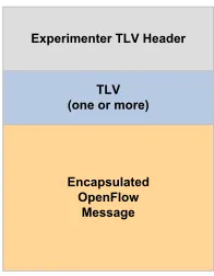
Experimenter TLV Header
TLV (one or more)
Encapsulated OpenFlow
Message
Figure 8: Experimenter TLV Message Format
This extension defines the Time TLV, as follows:
/* Time TLV Format. */ struct onf_time_tlv {
uint16_t type; /* ONF_TIME_TLV_TYPE. */
uint16_t length; /* 24 bytes.*/
uint64_t seconds; uint32_t nanoseconds; uint32_t flags;
uint8_t pad[4]; /* 64-bit alignment */
};
This extension defines the following TLV type:
/* TLV type */ enum onf_tlv_type {
/* Time TLV type. */ ONF_TIME_TLV_TYPE = 0xFA57, };
Time Format: The time format defined in this extension is similar to the one de-fined in [8]. It consists of two sub-fields; aseconds field, representing the integer portion of time in seconds, and ananosecondsfield, representing the fractional por-tion of time in nanoseconds. As defined in [8], time is measured according to the International Atomic Time (TAI) timescale. The epoch is defined as 1 January 1970 00:00:00 TAI.
Flags:The flags field is a bitmap that has the following structure:
/* Time TLV flags. */ enum onf_time_flags {
INCLUDE_TIME = 1 << 0; /* Indicates that this TLV includes a valid time field. */
GET_TIME = 1 << 1; /* Indicates that the REPLY message
INCLUDE_TIME: specifies whether the current time TLV includes a valid time field. When this flag is enabled, it indicates that the seconds and the nanoseconds fields include a valid time. TheINCLUDE_TIMEflag may be disabled when theGET_TIMEflag is enabled.
GET_TIME: this is relevant only to REQUEST message types. When this flag is enabled it indicates that the corresponding REPLY message must incorporate a valid time, indicating the execution time of the corresponding operation.
Note: when a message includes the time TLV at least one of the two flags,
INCLUDE_TIMEandGET_TIME, must be enabled.
References
[1] T. Mizrahi and Y. Moses, “Time-based updates in software defined networks,” in
the second workshop on hot topics in software defined networks (HotSDN), to ap-pear, 2013.
[2] N. McKeown, T. Anderson, H. Balakrishnan, G. Parulkar, L. Peterson, J. Rexford, S. Shenker, and J. Turner, “Openflow: enabling innovation in campus networks,”
SIGCOMM Comput. Commun. Rev., vol. 38, no. 2, pp. 69–74, Mar. 2008.
[3] Open Networking Foundation, “Openflow switch specification,” Version 1.3.2, 2013.
[4] ——, “OpenFlow Management and Configuration Protocol (OF-Config 1.1),” Ver-sion 1.1, 2012.
[5] R. Enns, M. Bjorklund, J. Schoenwaelder, and A. Bierman, “Network configura-tion protocol (NETCONF),” IETF, RFC 6241, 2011.
[6] T. Mizrahi and Y. Moses, “Time Capability in NETCONF,” IETF, draft-mm-netconf-time-capability, work in progress, 2013.
[7] Open Networking Foundation, “Openflow switch specification,” Version 1.0.0, 2009.