R E S E A R C H
Open Access
Effects of a powered ankle-foot orthosis
on perturbed standing balance
Amber R. Emmens
*, Edwin H. F. van Asseldonk and Herman van der Kooij
Abstract
Background: Lower extremity exoskeletons are mainly used to provide stepping support, while balancing is left to the user. Designing balance controllers is one of the biggest challenges in the development of exoskeletons. The goal of this study was to design and evaluate a balance controller for a powered ankle-foot orthosis and assess its effect on the standing balance of healthy subjects.
Methods: We designed and implemented a balance controller based on the subject’s body sway. This controller was compared to a simple virtual-ankle stiffness and a zero impedance controller. Ten healthy subjects wearing a powered ankle-foot orthosis had to maintain standing balance without stepping while receiving anteroposterior pushes. Center of mass kinematics, ankle torques and muscle activity of the lower legs were analyzed to assess the balance performance of the user and exoskeleton.
Results: The different controllers did not significantly affect the center of mass responses. However, the body sway based controller resulted in a decrease of 29% in the biological ankle torque compared to the zero impedance controller and a decrease of 32% compared to the virtual-ankle stiffness. Furthermore, the soleus muscle activity of the left and right leg decreased on average with 8%, while the tibialis anterior muscle activity increased with 47% compared to zero impedance.
Conclusion: The body sway based controller generated human-like torque profiles, whereas the virtual-ankle stiffness did not. As a result, the powered ankle-foot orthosis with the body sway based controller was effective in assisting the healthy subjects in maintaining balance, although the improvements were not seen in the body sway response, but in the subjects’ decreased biological ankle torques to counteract the perturbations. This decrease was a combined effect of decreased soleus muscle activity and increased tibialis anterior muscle activity.
Keywords: Standing balance, Ankle-foot orthosis, Balance control, Exoskeleton
Background
Exoskeletons have been successfully used to provide assis-tance during walking. For people with lower extremity impairments the focus is generally on rehabilitation [1–5] and gait restoration [6–8], while exoskeletons for healthy people aim to augment strength and endurance [9–13]. A particular goal of exoskeleton studies is to reduce the effort of walking. A key challenge is to overcome the neg-ative effects of the added weight of the exoskeleton. It was shown that when using passive or powered ankle-foot orthoses, it is possible to reduce the muscle activity of ankle plantar flexors [14,15].
*Correspondence:a.r.emmens@utwente.nl
Department of Biomechanical Engineering, University of Twente, Drienerlolaan 5, 7522 Enschede, NB, the Netherlands
While healthy users are able to walk in wearable exoskeletons without assistive devices, for people suffer-ing from neurological disorders such as a spinal cord injury this is difficult, if not impossible, due to affected balance. Except for the wearable exoskeleton “REX” (REX Bionics Ltd, New Zealand) [16], commercially available devices are used in combination with crutches for main-taining balance [3, 7, 17]. This implies that the users are supporting themselves and the exoskeleton in staying upright, although it would be desirable if the exoskeleton supported the user’s balance. Still, only a few studies have addressed the topic of exoskeleton balance control dur-ing walkdur-ing [6,18] or standing [19]. These studies mainly focused on controller implementation and not on its effect
on the user. In maintaining balance, the user and the exoskeleton should work in harmony and therefore it is essential to incorporate knowledge about human balance control in the controller.
Several models have been suggested to describe the dynamics of human standing balance control, based on full-state feedback [20–24] or center of mass (CoM) motion [25–27]. For full-state feedback, the human is modeled as a multi-link system and the state vector gen-erally consists of the angles and velocities of all the joints. How much each state contributes to a certain joint torque can be acquired by fitting experimental data to a model simulation. Through forward simula-tions it was shown that full-state feedback models are able to predict ankle and hip torques well in a lin-earized double-inverted pendulum model [22]. For CoM feedback, the whole body CoM of a human is gener-ally assumed to sway like a single inverted pendulum. This model has proven to be sufficient for describing the balance strategy known as the “ankle strategy,” which is dominant in quiet stance and other simple balanc-ing tasks [28]. Furthermore, previous studies have shown that CoM kinematics can be used to reproduce mus-cle activity patterns during both ankle and hip postural responses [25,26].
Our goal is to use an exoskeleton for balancing dur-ing standdur-ing and walkdur-ing and to assess the effect of the exoskeleton on the user. As a first step we tested balance controllers on a powered Ankle-Foot Orthosis (pAFO) and investigated standing balance in the sagittal plane. Since task-space goals, such as controlling CoM excur-sion, play an important role in standing balance, the pro-posed balance controller was based on CoM kinematics. The assistive torque that the pAFO had to deliver was calculated from the CoM kinematics according to the sin-gle inverted pendulum model. We compared this control law to a simple stiffness applied around the ankle, which
is equivalent to controlling a single inverted pendulum model in joint-space. Furthermore, ankle stiffness corre-sponded to the largest feedback gain of the full-state feed-back law for the ankle torque [21]. As such, the stiffness controller had the potential to positively affect balance performance, without introducing task-space complexity. The goal of this research is twofold: 1. to assess the effects of the controlled pAFO on the balance performance of the user; and 2. to assess the effects of the controlled pAFO on human effort, based on ankle joint kinetics and muscle activity of the ankle plantar and dorsiflexors. We hypoth-esized that, with the application of an assistive torque that is similar to the ankle torque humans generate when being perturbed, balance performance would improve, while the human contribution to the balance response would decrease.
Methods
In this study, the assistive effect of the pAFO was tested by means of experiments in which subjects had to main-tain balance, without stepping, while receiving external perturbations. Ethical approval for the experiments was given by the Human Research Ethics Committee of Delft University of Technology, the Netherlands.
Subjects
Ten healthy subjects (three female, mass 71±6 kg, height 1.81 ±0.07 m, mean ± SD) participated in the exper-iment after giving written informed consent. Based on the size and stiffness characteristics of the pAFO, par-ticipants were selected who were taller than 1.65 m, weighed less than 84 kg, and had an EU shoe size between 36 and 44.
Experimental setup
Figure1shows a schematic overview of the experimental setup.
a
b
The Achilles Ankle-Foot Orthosis
The Achilles [29] is a pAFO that can provide dorsi/plantar flexion torques to the ankle, while inversion and eversion are constrained. As shown in Fig.2, the complete device consists of two orthoses (1.5 kg each) and a backpack. Each orthosis is actuated by a motor and ball-screw spin-dle. The spindle is connected to the rotational joint of the orthosis by a leaf spring, such that a translation of the spindle results in a spring deflection and a joint torque. To measure the motor stroke and the joint rotation, the device is equipped with an incremental encoder on the motor axis and an absolute encoder at the rotational joint. Since the spring stiffness is known (410 Nm/rad) and the spring deflection depends on the motor stroke and the joint rotation, the torque that is delivered by the Achilles can be estimated [29]. In the Zero Impedance (ZI) condi-tion the spring defleccondi-tion, and therefore the joint torque, is minimized. There is no compensation for the inertia of the device, but the inertia effects are small.
The Achilles backpack contains a PC (EtherCAT Mas-ter) that communicates with the orthoses and other hard-ware modules (EtherCAT slaves). EtherLab (IgH, Essen, Germany) is used to compile MATLAB/Simulink (2014b,
Fig. 2The Achilles ankle-foot orthosis
The Mathworks, Natick, MA, USA) models into exe-cutables that can run on the real-time Linux EtherCAT master. During the experiments subjects did not wear the backpack, but it was hung behind them on parallel bars.
Perturbation device
An actuated perturbation device, referred to as “Pusher,” was used to provide forward perturbations at the pelvis. It consists of a motor (SMH60, Moog, Nieuw-Vennep, The Netherlands) located at the rear of the treadmill, con-nected to a horizontal push rod (0.8 m) through a lever arm (0.3 m), as shown on the right of Fig.1a. At the end of the push rod a modified universal hip abduction brace (Distrac Wellcare, Hoegaarden, Belgium) was attached, which was tightly worn by the subjects. A load cell (model QLA131, FUTEK, Los Angeles, CA, USA) was mounted on the lever arm for torque sensing [30]. The rod was approximately horizontal, such that a motor torque would result in forward pushing or backward pulling of the sub-ject. The motor was admittance controlled over Ethernet (User Datagram Protocol) at 1000 Hz, using xPC-target (The Mathworks, Natick, MA, USA).
Measurement equipment
To measure the orientation of the shank, thigh and trunk of the subject, three Xsens (Xsens Technologies B.V., Enschede, the Netherlands) MTx Inertial Measurement Units (IMUs) with integrated magnetometers were used. Each IMU was calibrated by defining its axis of rotation to correspond to the mediolateral axis of the subject. This calibration was done by letting each subject make a squat movement at the start of the first trial. The signals of the IMU’s were made available real-time on the EtherCAT Master through a RS232-EtherCAT converter box.
Besides motion data, ground reaction forces and moments were collected using a custom made split-belt instrumented treadmill (Y- Mill, Motek, Amsterdam, The Netherlands) that has force plates beneath each belt. Fur-thermore, the Delsys Trigno Lab Wireless EMG System (Delsys Inc., Natick, USA) was used to record EMG signals on the gastrocnemius medialis (GM), soleus (Sol) and tib-ialis anterior (TA). The EMG sensors were equipped with a fourth order Butterworth filter that rejected frequencies above 450 Hz.
Control strategies Body sway controller
The body sway controller, PDcom, was a
proportional-derivative controller that uses the CoM motion as an input. The control law for the PDcomis as follows:
τach=KP
θswayd−θsway
+KD
˙
θswayd− ˙θsway
(1)
whereτachis the desired support torque that the Achilles
gains respectively, θsway is the body sway angle that is
dependent on the CoM location, and subscriptdindicates a desired value. A complete list of symbols is provided in Table1.
The body sway angle was estimated using a human model with four rigid segments: a foot, shank, thigh and head-arms-trunk segment (Fig. 3). The segments’ lengths, inertias, masses and CoM were estimated using the method described by Winter (2009) [31]. The orien-tation of the segments was obtained using the IMUs and expressed with respect to the baseline pose. For this base-line pose, subjects were requested to stand comfortably upright. Then all segment angles and the body sway angle were set to zero.
The desired body sway θswayd was initially set to zero, matching the zero value of the body sway angle when a subject was in the baseline pose. During the experi-ments the desired body sway angle was adapted to match the body sway angle of the steady pose that subjects maintained between perturbations, allowing for natural variation in forward lean. This was done by updating the desired body sway when the subject’s body sway veloc-ity remained close to zero for over 3 s. In a pilot test this duration had shown to be long enough to be sure that the subject had adopted a new steady pose. The updated desired body sway angle was then set to the average of the body sway angle during those 3 s. To prevent instanta-neous changes in the desired body sway angle, the signal was passed through a second order low-pass filter with a cut-off frequency of 0.5 Hz Fig.4shows an example of how the desired body sway was adapted to a new steady pose.
To obtain the body sway velocity the body sway was differentiated and low-pass filtered using a second order
Table 1List of symbols
Symbol Meaning
FCx Sum of the horizontal ground reaction forces
FCy Sum of the vertical ground reaction forces
g Gravitational acceleration
hA Ankle height w.r.t. the ground
K Proportional gain of the virtual-ankle stiffness controller
KD Derivative gain of the body sway controller
KP Proportional gain of the body sway controller
lcom Height of the center of mass in upright stance w.r.t. the ankle
M Subject mass
px Center of pressure in anteroposterior direction w.r.t. the ankle
θsway Body sway angle
τach Desired support torque
τtot Total torque applied to the ankle
φA Ankle joint angle
Fig. 3Computation of the body sway angleθswaybased on a rigid link
model. The variablesφare joint angles,mnare segment masses and
Mis the total body mass located at the CoM. Left: model in baseline pose. The model is placed in a right-handed coordinate system. Segment rotations and moments are positive in counter-clockwise direction. Middle: the joint angles are defined as the angle of segment
nminus the angle of segmentn−1. Segment angles are zero in the baseline pose. Right: Based on segment angles and masses the whole body CoM can be computed. Similar to the segment angles, the body sway angle is positive in counter-clockwise direction
Butterworth filter with a cut-off frequency of 10 Hz. The desired body sway velocity was set to zero.
The control gains were normalized to the subject mass Mand CoM heightlcom:
KP=Mglcom
KD=0.3
Ml2
comKP
wheregis the gravitational acceleration. The gainKPwas
chosen such that the gravitational stiffness was compen-sated. As a result the subject was able to stabilize the system with a minimal amount of effort. The subject was assumed to provide the feed-forward torque to maintain the desired body sway angle himself. GainKD consisted
of a normalization partMl2
comKPmultiplied by a factor
0.3. This multiplication factor was tuned empirically to maximize damping without causing unstable oscillations.
Virtual-ankle stiffness controller
The Pankleis a proportional controller that takes the ankle
angleφAas an input:
Fig. 4Adaptation of the desired body sway angle to a new steady pose. Top: body sway angle and desired body sway angle, bottom: scaled body sway velocity. The vertical dashed lines indicate the time frame in which the body sway velocity is approximately zero and the average body sway angle is computed. The desired body sway angle moves slowly to this average value
as zero, corresponding to the ankle angle in the baseline pose. Damping was provided by the inherent properties of the ankle of the subject wearing the Achilles.
The control gainKwas chosen to be:
K =Mglcom
which is the same as the gainKP of the body sway
con-troller. Therefore, if subjects adjusted only their ankle joint angle, while keeping their foot flat on the floor, the stiffness provided by the virtual-ankle stiffness controller was equal to the stiffness provided by the body sway controller.
Protocol
Each subject was tested under three control conditions: ZI, PDcom and Pankle in a total of 10 trials. The order of
the Panklecontroller (three trials) and the PDcomcontroller
(three trials) was reversed after each subject. To pre-vent familiarization with the first controller influencing the second, a ZI trial was done in between. Furthermore, the PDcomand Panklecontrolled trials were preceded and
succeeded by ZI trials to let subjects get used to the per-turbation, collect baseline data and to check for fatiguing effects. The trial order for each subject is shown in Table2. Before the first Pankleand PDcomtrial, subjects had one
minute of practice time to feel the effect of the controller. Before the experiments, subjects were instructed to try their best to maintain balance without stepping. They were instructed to cross their arms in front of their chests to prevent arm movement while they balanced. Further-more, subjects were asked to stand still between pertur-bations with their weight evenly distributed on both feet
and to return to their initial pose after a perturbation was applied.
During the experiments, the Pusher provided forward perturbations at the pelvis with two different magni-tudes. The reference force was a rectangular pulse with a duration of 0.2 s and a magnitude of 0.08Mg (N) (small perturbation) or 0.14Mg(N) (large perturbation), where M is the mass of the subject and g the gravita-tional acceleration. Although the Pusher motors could not track the desired reference force perfectly, the provided pushes were consistent (Fig. 1b). In each trial subjects received 15 perturbations of each magnitude in a random order. The time between perturbations varied between 8 and 12 s.
After five trials subjects had a five minute break. Addi-tionaly, subjects were given a rest when needed.
Data collection and analysis
IMU data and joint encoder data were collected on the PC in the Achilles backpack at a sampling frequency of 100 Hz. Force plate, Pusher and EMG sensor data were collected on the XPC target PC at 1000 Hz. A signal com-posed of pseudo-random numbers and a time interval of
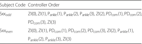
Table 2Experiment trial order. Subjects were coded S02 to S11
Subject Code Controller Order
Sxxodd ZI(0), ZI(1), Pankle(1), Pankle(2), Pankle(3), ZI(2), PDcom(1), PDcom(2),
PDcom(3), ZI(3)
Sxxeven ZI(0), ZI(1), PDcom(1), PDcom(2), PDcom(3), ZI(2), Pankle(1),
Pankle(2), Pankle(3), ZI(3)
0.1 s between two samples was sent from the XPC target to the Achilles PC and logged on both systems. By comput-ing the cross-correlation between the (resampled) signals, the delay between the systems was established and used for data synchronization.
The force plate and Pusher data were resampled to 100 Hz. To remove movement artifacts, the EMG data were first high-pass filtered in both forward and reverse direction using a third order Butterworth filter, resulting in a sixth order zero-lag filter with a cut-off frequency of 10 Hz. Then they were rectified by taking the absolute value, and low-pass filtered using a sixth order zero-lag filter with a cut-off frequency of 5 Hz to create an envelope.
To investigate the effect of the controllers on the stand-ing balance of the subjects, the body sway, body sway velocity, ankle torques and muscle activity of the lower legs were analyzed. The body sway velocity was used to obtain a measure of the recovery time, that is, the subject was assumed to have recovered from a perturbation when the absolute body sway velocity was lower than 0.015 rad/s. This threshold was based on the computed varia-tion in body sway velocity during quiet stance. The ankle torques can provide insight on how much the subject and device are contributing to maintaining balance. There-fore, the total ankle torque was derived using the center of pressure (CoP) in the anteroposterior (AP) direction. The CoP was computed from the measured moments and normal forces of the force plates. Since the location of the subject on the force plates was known, the CoP could be computed with respect to the time varying location of the ankle of the subject. For the estimation of the total dorsi/plantar flexion torque applied to the ankle, the mass of the foot was neglected. Then the total ankle torque
τtot=FCypx−FCxhA (3)
where FCy is the vertical ground reaction force, px the
CoP in the AP direction with respect to the ankle,FCxthe
horizontal ground reaction force and hA the time
vary-ing ankle height. The torque applied by the Achilles was estimated from the leaf spring deflection, which was mea-sured by differences between the motor and joint encoder readings. Subtracting this torque from the total torque resulted in the torque applied by the subject (the bio-logical ankle torque). The total ankle torque, the torque applied by Achilles and the biological ankle torque were all normalized by a factorMgl1
com.
Data from the ZI, Pankleand PDcomtrials 1:3 were used;
ZI(0) was excluded from the analysis to reduce the effect of subjects not being used to the perturbations. All data were split to extract the perturbation responses, and the first two perturbations of each trial were removed.
We computed the root-mean-square (RMS) of the body sway response from the start of a perturbation until the
average time at which subjects had recovered. There-fore, the average recovery time was calculated over all subjects and all controllers. Additionally, we computed the RMS of the normalized total ankle torque, normal-ized biological ankle torque and the EMG envelopes, but then from the start of a perturbation until the aver-age time at which the normalized total ankle torque had returned to a steady-state value. We assumed that the steady-state was reached when the absolute value of the derivative of the normalized total ankle torque was smaller than 0.02. This threshold was based on the variation in the derivative of the normalized total ankle torque dur-ing quiet stance. To compare the muscle activities of all the subjects, the means of the RMS values of the EMG envelopes in the Pankleand PDcomtrials were normalized
by dividing them by the mean from the corresponding ZI trials.
Statistical procedures
Since not all data were normally distributed, we ana-lyzed the data using non-parametric tests. Furthermore, both perturbation levels were analyzed separately. We used the Wilcoxon signed rank test to compare PDcom
to the two other control cases by testing for differ-ences in RMS body sway, recovery time, RMS torque and RMS EMG.
The overall significance level was set atp < 0.05. To correct for two comparisons (PDcomcompared to ZI and
Pankle), for each test the significance level was set atp <
0.05/2. To compute effect sizes,z-values were transferred to r-values, wherer=0.1 corresponded to a small effect, r=0.3 a medium effect and r=0.5 a large effect [32]. All statistical procedures were carried out with SPSS Statistics 24 (IBM, New York, USA).
Results
Controller behavior
We investigated the general behavior of the virtual-ankle stiffness and body sway controllers by analyzing their inputs and outputs.
Due to heel lift, the ankle showed plantar flexion in response to a perturbation, represented by an increasing ankle angle in Fig. 5a. However, the body’s CoM sways forward, which corresponds to the decreasing body sway angle in Fig. 5b. Therefore, the output torques of the Pankle controller and PDcom controller are in opposite
directions: a dorsiflexion torque for Pankle(Fig.5c) and a
plantar-flexion torque for PDcom(Fig.5d).
A comparison of the normalized controller output torques and the normalized biological ankle torque in the ZI trial shows that for both perturbation sizes the torques generated by the PDcom follow a similar trend
a
b
c
d
Fig. 5Controller inputs and outputs of a representative subject.aThe ankle angle measured in the Pankletrial, compared to the ankle angle
measured in the ZI and PDcomtrials.bThe body sway angle measured in the PDcomtrial, compared to the body sway angle measured in the ZI and
Pankletrials.cNormalized output torque of the Panklecontroller.dNormalized output torque of the PDcomcontroller. The grey boxes indicate the
perturbation period. Similar results were obtained at a group level
these differences in support torques, subjects were able to maintain balance using each of the controllers.
CoM kinematics
The amplitude of the body sway angle hardly varied with the controller used, for small and large perturbations (Fig.7a,b). The results of the Wilcoxon signed rank tests showed no significant differences between the RMS body sway with the PDcom and the RMS body sway with the
other two controllers (Table3). The recovery time, derived from the body sway velocity, was also similar for all con-trollers for small perturbations and large perturbations (Fig.7c,d, Table3).
Ankle joint kinetics
For both the small and the large perturbations, there was a decrease in normalized biological ankle torque for the PDcom compared to ZI and Pankle, while the normalized
a
b
a
b
c
d
Fig. 7CoM kinematics, mean over all subjects.aBody sway angle in response to a small perturbation.bBody sway angle in response to a large perturbation.cBody sway velocity in response to a small perturbation.dBody sway velocity in response to a large perturbation. The grey boxes indicate the perturbation period
total ankle torque stayed approximately the same (Fig.8, Table 4). The decrease in median RMS normalized bio-logical ankle torque over all subjects was particularly large in response to large perturbations: a 29% decrease for the PDcom compared to ZI, and a 32% decrease
com-pared to Pankle. The results of the Wilcoxon signed rank
tests showed that the normalized biological ankle torque response to a large perturbation was significantly lower for the PDcom(Mdn=0.063) compared to ZI (Mdn=0.089),
z = −2, 701,p = 0.004,r = 0.60 and Pankle (Mdn =
0.093),z = −2, 803,p = 0.002,r = 0.63. For the small perturbations the normalized biological ankle torque was only significantly lower for the PDcomcompared to ZI, but
not compared to Pankle(Table4).
EMG
Generally, when the PDcomwas applied, subjects showed a
decrease in soleus activity and an increase in tibialis ante-rior activity with respect to ZI, as shown for a representa-tive subject in Fig.9. These results were also observed at a group level in response to large perturbations (Fig.10b).
In that case the median of the RMS soleus muscle activ-ity of the left and right leg decreased on average with 8%, while the median of the RMS tibialis anterior muscle activity increased with 47% compared to zero impedance. The results of the Wilcoxon signed rank tests showed that the SolL activity significantly decreased using the PDcom
(Mdn = 0.88) compared to ZI,z = −2, 293,p = 0.02, r = 0.50, while the TAR activity significantly increased (Mdn = 1.56),z = −2, 803,p = 0.002,r = 0.63. Test results for the opposite leg (SolR and TAL) were nearly sig-nificant (Table5). In comparison with Pankle, PDcomalso
resulted in a consistent decrease in plantar flexor mus-cle activity and an increase in dorsiflexor musmus-cle activity (Fig.10), however this effect was only significant for TAR (Table5).
Discussion
The goal of this study was to develop a controller that provides balance support for an exoskeleton and its user. Therefore, we tested a body sway controller and a virtual-ankle stiffness controller on a pAFO, and assessed their
Table 3Statistical test results from the Wilcoxon signed rank test for RMS body sway and recovery time
Small perturbations Large perturbations
Variable PDcomvs. ZI PDcomvs. Pankle PDcomvs. ZI PDcomvs. Pankle
body sway z= −0.255,p=0.846 z= −0.153,p=0.922 z= −0.357,p=0.770 z= −0.051,p=1.000
a
b
c
d
Fig. 8Normalized total ankle torque and normalized biological ankle torque.aTorques in response to a small perturbation, mean over all subjects. bTorques in response to a large perturbation, mean over all subjects.cMean of the RMS of the normalized torques computed over the small perturbations for each subject individually.dMean of the RMS of the normalized torques computed over the large perturbations for each subject individually. The grey boxes indicate the perturbation period
effects on standing balance. The body sway controller showed a human-like torque profile—that is, a torque profile that has the same shape as the biological ankle torque profile with ZI—whereas the virtual-ankle stiff-ness did not (Fig.6). Firstly, we hypothesized that when a human-like assistive torque was provided, the balance performance would improve. However, subjects did not use the provided support torques to respond to a per-turbation quicker or to reduce the body sway. Secondly, we expected that the human contribution to the balance response would decrease. This was indeed the case, since subjects reduced their own contribution to ankle torque.
In the scarce literature on balance control of exoskele-tons, no results have been reported on the effects on the biological ankle torque. Therefore, we compared our results with pAFO locomotion studies. For torque assisted walking, decreased biological ankle torques were reported [14,15]. In these studies, the support torque profiles that
were provided to the subjects had a similar shape as the biological torque profiles during unassisted walking. These findings are similar to our results on pAFO balance control.
In our work, the decrease in biological ankle torque was a combined effect of decreased soleus activity (8%) and increased tibialis anterior activity (47%). This is similar to the results of Collins et al. (2015) [14], who also reported decreased soleus activity and increased tibialis anterior activity (although in combination with affected gastroc-nemicus activity), but different from the results of Kao et al. (2010), who only showed a decrease in soleus activ-ity, without an increase of tibialis anterior activity [15]. For balance recovery from a forward perturbation the plantar flexor muscles are typically active. However, the increased tibialis anterior activity indicates co-contraction of the lower leg muscles. A possible reason for this co-contraction is that it could be an effective way to decrease
Table 4Statistical test results from the Wilcoxon signed rank test for RMS normalized total ankle torque and RMS normalized biological ankle torque
Small perturbations Large perturbations
Variable PDcomvs. ZI PDcomvs. Pankle PDcomvs. ZI PDcomvs. Pankle
total torque z= −0.866,p=0.432 z= −0.051,p=1.000 z= −1.886,p=0.064 z= −1.886,p=0.064
bio. torque z= −2.497,p=0.010a z= −0.866,p=0.432 z= −2.701,p=0.004a z= −2.803,p=0.002c
aRMS PD
com<RMS ZI cRMS PD
Fig. 9EMG envelopes of a representative subject, large perturbations. The grey boxes indicate the perturbation period, the RMS was computed from the start of the perturbation period until the dotted vertical line. Similar results were obtained at a group level
the biological ankle torque, while limiting the decrease in joint stiffness. Since the EMG signal is not an abso-lute measure of muscle activity, it is not immediately clear whether the total muscle activity has increased or decreased. We expressed the RMS EMG with respect to ZI to be able to analyze the effects of the controllers on the muscle activities across subjects. This normalization
impacts the interpretation of the 8% decrease in soleus activity and 47% increase in tibialis anterior activity, since the absolute changes in muscle activity are dependent on the muscle activity with ZI. Although in unassisted standing balance mainly plantar flexor muscles are active during recovery from a forward perturbation, Maki and Ostrovski (1993) reported a substantial amount of
co-a
b
Table 5Statistical test results from the Wilcoxon signed rank test for normalized RMS EMG. RMS EMG was normalized to ZI
Small perturbations Large perturbations
Muscle PDcomvs. 1 (ZI) PDcomvs. Pankle PDcomvs. 1 (ZI) PDcomvs. Pankle
GML z= −1.362,p=0.203 z= −1.599,p=0.129 z= −1.599,p=0.129 z= −1.244,p=0.250
GMR z= −1.988,p=0.049 z= −1.988,p=0.049 z= −1.988,p=0.049 z= −1.580,p=0.131
SolL z= −0.968,p=0.375 z= −0.255,p=0.846 z= −2.293,p=0.02a z= −1.274,p=0.232
SolR z= −1.784,p=0.084 z= −0.633,p=0.557 z= −2.090,p=0.037 z= −0.561,p=0.625
TAL z= −2.073,p=0.039 z= −0.889,p=0.426 z= −2.192,p=0.027 z= −1.362,p=0.203
TAR z= −2.191,p=0.027 z= −0.561,p=0.625 z= −2.803,p=0.002b z= −2.701,p=0.004d
aRMS PD
com<RMS ZI bRMS PD
com>RMS ZI dRMS PD
com>RMS Pankle
contraction for forward sway induced by backward plat-form perturbations, which increased with increasing per-turbation magnitude [33]. Since the perturbations in our experiment were also large, we would expect substantial tibialis anterior activity with ZI. Therefore, it is not likely that the relatively large increase in tibialis anterior activ-ity is a result of low muscle activactiv-ity with ZI. Consequently, we cannot be conclusive about whether the total muscle activity increased or decreased through the concurrent changes in soleus and tibialis anterior activity.
Modifications in muscle activity can be feedback-driven or a result of feed-forward adaptation over time. In this study the reduction of the biological ankle torque when using the body sway controller could already be observed at the beginning of a trial and remained constant over that trial. This suggests that the changes in muscle activity are feedback-driven adjustments. Similar feedback responses were found for walking pattern adaptation in the pres-ence of velocity-dependent resistance, but in combination with feed-forward adaptive strategies [34]. It is possible that feed-forward adaptation could also occur in standing balance with a controlled pAFO, but that the exposure to the controllers in this study was too short to demonstrate this effect.
Besides a decreased human contribution to ankle torque, we also found that the body sway in response to a perturbation was similar for all controllers (Fig.7). It is not directly clear why the body sway stayed approximately the same, while the provided support torques were dif-ferent. For example, in Functional Electrical Stimulation controlled standing, healthy subjects do change their body sway when different control strategies are applied [35]. There are several explanations for the unchanged body sway. Firstly, according to the inverted-pendulum model, the total torque must increase to reduce the body sway. In case of a large perturbation, it is not always possible to increase the total ankle torque considering that the CoP is already at the edge of the base of support. However, this does not hold for the small perturbations for which we saw
the same effects. Secondly, subjects may prefer to reduce effort when they are confidently able to maintain balance. This preference of minimizing effort instead of body sway was also reported in standing balance identification stud-ies, through comparisons between optimal and identified neural feedback gains [23,36]. Lastly, subjects may need more training time to adapt their body sway response.
The body sway controller and virtual-ankle stiffness controller are not only different in the sense that they require different angles as an input. For one thing, for the sake of simplicity the virtual-ankle stiffness controller did not have a velocity dependent component. For another thing, for the body sway controller we allowed the desired body sway angle to adapt to a new steady pose, while for the virtual-ankle stiffness controller the desired ankle angle was kept constant. As a result of keeping the desired ankle angle constant, there was an offset from zero in the torque provided by the pAFO when the virtual-ankle stiff-ness controller was used (Fig.6). Yet, we do not think that the virtual-ankle stiffness controller would perform better when a velocity dependent component was added to the control law, or when the desired ankle angle was updated to a new steady pose, since the support torques generated in response to a perturbation would still be small, or even in opposite direction (Fig.6).
A practical implication of using a body sway controller is that the CoM location should be estimated on-line. Generally, exoskeletons are equipped with joint encoders. While this is sufficient for simpler controllers, such as the virtual-ankle stiffness, for a body sway estimation addi-tional sensors are needed, which adds complexity to the setup. We used three IMUs and anthropometric data to make a CoM estimation, but simpler methods based on a single IMU have already been shown to give good results during walking [37].
support torques. Healthy subjects reduced their own ankle torques, but paraplegics, depending on the level of injury, typically cannot provide large ankle torques them-selves. Therefore, a future direction is to test these balance controllers on an exoskeleton for people with a spinal cord injury who are not able to balance themselves.
Conclusion
In this study we investigated the effects of a pAFO on the standing balance of healthy subjects. We found that when using a controller that uses body sway motion as an input, effective supportive torques could be provided. These support torques followed a similar trend to the ankle torques humans would provide in response to a per-turbation. Although the CoM kinematics remained unaf-fected with the body sway controller, the biological ankle torque decreased when the body sway controller was implemented. This was a result of the combined effects of decreased soleus muscle activity and increased tib-ialis anterior muscle activity. Subjects were able to quickly adapt their ankle torques to the torques provided by the ankle exoskeleton. These results suggest a preference for reducing effort instead of further improving body sway.
Abbreviations
AP: Anteroposterior, CoM: Center of mass, CoP: Center of pressure, GM: Gastrocnemius medialis, IMU: Inertial measurement unit, pAFO: powered Ankle-Foot Orthosis, RMS: Root-mean-square, Sol: Soleus, TA: Tibialis anterior, ZI: Zero impedance
Funding
The work presented here was performed in the SYMBITRON project which is supported by EU research program FP7, FET-Proactive initiative “Symbiotic human-machine interaction” (ICT-2013-10) under project contract #611626. The SYMBITRON project is coordinated by the University of Twente.
Availability of data and materials
The datasets used and/or analyzed during the current study are available from the corresponding author on request.
Authors’ contributions
AE, EA and HK designed the study and interpreted the data, AE collected and analyzed the data and wrote the manuscript, EA and HK revised the manuscript. All authors read and approved the final manuscript.
Ethics approval and consent to participate
Ethical approval for the experiments was given by the Human Research Ethics Committee of TUDelft, the Netherlands. Subjects gave written informed consent prior to the experiments.
Competing interests
The authors declare that they have no competing interests.
Publisher’s Note
Springer Nature remains neutral with regard to jurisdictional claims in published maps and institutional affiliations.
Received: 25 August 2017 Accepted: 1 June 2018
References
1. Veneman JF, Kruidhof R, Hekman EEG, Ekkelenkamp R, van Asseldonk EHF, van der Kooij H. Design and evaluation of the lopes exoskeleton robot for interactive gait rehabilitation. IEEE Trans Neural Syst Rehabil Eng. 2007;15(3):379–86.
2. Jezernik S, Colombo G, Keller T, Frueh H, Morari M. Robotic orthosis lokomat: A rehabilitation and research tool. Neuromodulation. 2003;6(2): 108–15.
3. Strickland E. Good-bye, wheelchair. IEEE Spectrum. 2012;49(1):30–2. 4. Bortole M, Venkatakrishnan A, Zhu F, Moreno JC, Francisco GE, Pons JL,
Contreras-Vidal JL. The h2 robotic exoskeleton for gait rehabilitation after stroke: Early findings from a clinical study. J NeuroEngineering Rehabil. 2015;12(1):1–14.
5. Aach M, Cruciger O, Sczesny-Kaiser M, Höffken O, Meindl RC, Tegenthoff M, Schwenkreis P, Sankai Y, Schildhauer TA. Voluntary driven exoskeleton as a new tool for rehabilitation in chronic spinal cord injury: A pilot study. Spine J. 2014;14(12):2847–53.
6. Wang S, Wang L, Meijneke C, van Asseldonk E, Hoellinger T, Cheron G, Ivanenko Y, La Scaleia V, Sylos-Labini F, Molinari M, Tamburella F, Pisotta I, Thorsteinsson F, Ilzkovitz M, Gancet J, Nevatia Y, Hauffe R, Zanow F, van der Kooij H. Design and control of the mindwalker exoskeleton. IEEE Trans Neural Syst Rehabil Eng. 2015;23(2):277–86. 7. Esquenazi A, Talaty M, Packel A, Saulino M. The rewalk powered
exoskeleton to restore ambulatory function to individuals with thoracic-level motor-complete spinal cord injury. Am J Phys Med Rehabil. 2012;91(11):911–21.
8. Farris RJ, Quintero HA, Murray SA, Ha KH, Hartigan C, Goldfarb M. A preliminary assessment of legged mobility provided by a lower limb exoskeleton for persons with paraplegia. IEEE Trans Neural Syst Rehabil Eng. 2014;22(3):482–90.
9. Zoss AB, Kazerooni H, Chu A. Biomechanical design of the berkeley lower extremity exoskeleton (bleex). IEEE/ASME Trans Mechatron. 2006;11(2):128–38.
10. Walsh CJ, Endo K, Herr H. A quasi-passive leg exoskeleton for load-carrying augmentation. Int J Humanoid Robot. 2007;4(3):487–506. 11. Zhang J, Fiers P, Witte KA, Jackson RW, Poggensee KL, Atkeson CG,
Collins SH. Human-in-the-loop optimization of exoskeleton assistance during walking. Science. 2017;356(6344):1280–3.
12. Panizzolo FA, Galiana I, Asbeck AT, Siviy C, Schmidt K, Holt KG, Walsh CJ. A biologically-inspired multi-joint soft exosuit that can reduce the energy cost of loaded walking,. J Neuroengineering Rehabil. 2016;13(1):43. 13. Ding Y, Panizzolo FA, Siviy C, Malcolm P, Galiana I, Holt KG, Walsh CJ.
Effect of timing of hip extension assistance during loaded walking with a soft exosuit. J Neuroengineering Rehabil. 2016;13(1):87.
14. Collins SH, Bruce Wiggin M, Sawicki GS. Reducing the energy cost of human walking using an unpowered exoskeleton. Nature. 2015;522(7555):212–5.
15. Kao P-C, Lewis CL, Ferris DP. Invariant ankle moment patterns when walking with and without a robotic ankle exoskeleton. J Biomech. 2010;43(2):203–9.
16. Rex Bionics Ltd. Product Information - Rex Bionics.https://www. rexbionics.com/product-information/. Accessed 13 Nov 2017. 17. Parker Haniffin Corp. Indego-Powering People Forward.http://www.
indego.com/indego/en/home. Accessed 14 Dec 2016.
18. Wang L, Wang S, van Asseldonk EHF, van der Kooij H. Actively controlled lateral gait assistance in a lower limb exoskeleton. In: 2013 IEEE/RSJ International Conference on Intelligent Robots and Systems. 445 Hoes Lane Piscataway: IEEE; 2013. p. 965–970.
19. Rajasekaran V, Aranda J, Casals A, Pons JL. An adaptive control strategy for postural stability using a wearable robot. Robot Auton Syst. 2015;73:16–23.
20. Kuo AD. An optimal control model for analyzing human postural balance. IEEE Trans Biomed Eng. 1995;42(1):87–101.
21. Park S, Horak FB, Kuo AD. Postural feedback responses scale with biomechanical constraints in human standing. Exp Brain Res. 2004;154(4):417–27.
22. Afschrift M, Jonkers I, de Schutter J, de Groote F. Mechanical effort predicts the selection of ankle over hip strategies in nonstepping postural responses. J Neurophys. 2016;116(4):1937–45.
23. Kiemel T, Zhang Y, Jeka JJ. Identification of neural feedback for upright stance in humans: Stabilization rather than sway minimization. J Neurosci. 2011;31(42):15144–53.
25. Welch TDJ, Ting LH. A feedback model reproduces muscle activity during human postural responses to support-surface translations. J Neurophys. 2008;99(2):1032–8.
26. Welch TDJ, Ting LH. A feedback model explains the differential scaling of human postural responses to perturbation acceleration and velocity. J Neurophys. 2009;101(6):3294–309.
27. Peterka RJ. Sensorimotor integration in human postural control. J Neurophys. 2002;88(3):1097–118.
28. Horak FB, Nashner LM. Central programming of postural movements: Adaptation to altered support-surface configurations. J Neurophys. 1986;55(6):1369–81.
29. van Dijk W, Meijneke C, van der Kooij H. Evaluation of the achilles ankle exoskeleton. IEEE Trans Neural Syst Rehabil Eng. 2017;25(2):151–60. 30. Vlutters M, van Asseldonk EHF, van der Kooij H. Center of mass
velocity-based predictions in balance recovery following pelvis perturbations during human walking. J Exp Biol. 2016;219(10):1514–23. 31. Winter DA. Anthropometry. In: Biomechanics and Motor Control of
Human Movement. New York: John Wiley & Sons, Inc.; 2009. p. 82–106. 32. Cohen J. A power primer. Psychol Bull. 1992;112(1):155–9.
33. Maki B, Ostrovski G. Scaling of postural responses to transient and continuous perturbations. Gait Posture. 1993;1(2):93–104.
34. Lam T, Anderschitz M, Dietz V. Contribution of feedback and feedforward strategies to locomotor adaptations. J Neurophys. 2006;95(2):766–73. 35. Huryn TP, Blouin JS, Croft EA, Koehle MS, der Loos HFMV. Experimental
performance evaluation of human balance control models. IEEE Trans Neural Syst Rehabil Eng. 2014;22(6):1115–27.
36. van der Kooij H, Peterka RJ. Non-linear stimulus-response behavior of the human stance control system is predicted by optimization of a system with sensory and motor noise. J Comput Neurosci. 2011;30(3):759–78. 37. Floor-Westerdijk MJ, Schepers HM, Veltink PH, van Asseldonk EHF,