121
International Journal of Innovative and Emerging
Research in Engineering
e-ISSN: 2394 – 3343 p-ISSN: 2394 – 5494
DESGIN AND DEVELOPMENT OF A VISION SYSTEM FOR
WASHER INSPECTION
Vignesh Sundara,Prasad Alibadeb and Priyanka Ghanwatc
Department of Electronics and Telecommunication, Tathawade, pune and India Department of Electronics and Telecommunication, Tathawade, pune and India Department of Electronics and Telecommunication, Tathawade, pune and India
ABSTRACT:
This paper provides a simple vision system, a special purpose machine (SPM) designed for inspection of mechanical components like ball bearings, small nuts, bolts, washers etc. Manual inspection may lead to loss of material, labor, time for production and the inaccuracy in dimension measurement. Machine Vision (MV) system is advanced automated system which is adopted and researched for increase in productivity, for better accuracy and eliminating the human errors. This paper specially describes inspection of washers which are primarily used between nuts and bolts to fix them tightly. The main purpose of our work is to check surface defects and dimension verification. Keywords: Machine vision system, Controller, pressure gauge.
I. INTRODUCTION
Vision system is the application of a computer vision to industry. The important specification in any vision system are sensitivity and resolution. Sensitivity and resolution of a camera which captures the image of moving object. One of the most common application of vision system in manufacturing industries for the inspection of manufactured food, small electronic components, automobiles, etc. This system work as inspector which visually inspects the parts to decide their quality. So the vision system uses the high resolution digital camera, the controller to perform all the operation, the image processing software for the inspection. This vision system performs all tasks serially which are programmed in a controller. It performs tasks such as counting the objects on the conveyor, searching the surface defects, dimensional defects and counting the OK parts.
122
II. SYSTEM ARCHITECTURE
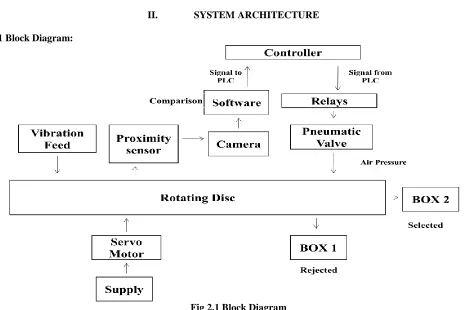
2.1 Block Diagram:
Fig 2.1 Block Diagram
Working of the system is very simple which starts from capturing the image with the help of camera. Before camera capture the image first proximity sensor senses the object on the rotating disc and it gives trigger to both cameras. After capturing the image, it is sent to the image processing software. Image processing software which inspects the object i.e. surface defect and the dimension of the object. Here using this software we are going to check the inner diameter (ID) and outer diameter (OD) and the surface quality with the help of camera1 (CAM1) and the height with the help of camera2 (CAM2). After the comparison process in the image processing software if the positive pulse is given to the PLC controller then it turns on the pneumatic valve to push the washer into reject box i.e. either because of surface defect or dimension defect. If the PLC get negative pulse it will not turn on the valve and the washer automatically fall into the select box which is at the end of conveyor. That means washer is having no defect.
2.2 COMPONENTS USED:
A. Bowl Feeder: This is used to store the manufactured washers. It supplies washers to conveyor. The speed of this feeder is liner which is controlled by the variable.
B. Conveyor: conveyor is used to move object from one place to another in production line. The conveyor belt used should be transparent in order to illuminate the washer image. We have to keep the speed of conveyor motor optimum so that there is little time gap between the consecutive inspection and rejection of washer.
C. Sensor: An electronic sensor converts the physical values into analog or digital electrical signal. Here we are using proximity sensor to sense the washer. Proximity sensor is able to sense the nearby object without any physical contact. A proximity sensor often emits an electromagnetic or electrostatic field or a beam of electromagnetic radiation and looks for changes in the field or return signal. The maximum distance that this sensor can senses is defined ‘nominal range’. The main feature of proximity sensor is its high reliability and long functional life because of absence of mechanical part and lack of physical contact with object.
D. Camera: Two high resolution HD cameras are used to capture the clear image. One used to capture ID, OD and surface
123 system with the help of the program stored in its ROM. There are many PLC which can be used as controller. When it obtain data from the computer it controls pneumatic valve with the help of relays.
F. Pneumatic Valve: It is connected to the output terminal of the controller. Pneumatic valve exerts the small air pressure only when it get positive pulse response from the controller which means part does not meet the standard part and needed to be rejected.
2.3 PROPOSED SYSTEM
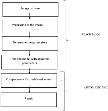
There are two modes in the system which are the teach mode and the automatic mode. In the teach mode the training parameters are determined and stored in the machine. The image of the washer is captured and parameters are determined. These are stored as a template in the machine which is used in the automatic mode.
In the automatic mode the washers which are to be inspected are sent one by one and image of each washer is captured. The dimensional parameters of each washer is compared with the predefined template stored in the memory. If the dimensions match then the washers are selected. If the proper match does not take place the washers are rejected.
TEACH MODE
AUTOMATIC MODE
Fig 2.2 PROCESS FLOW. Reprinted from "Implementation of Shape – Based Matching Vision System in
Flexible Manufacturing System" by L. W. Teck, M. Sulaiman, H. N. M. Shah and R. Omar, 2010.
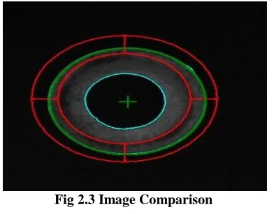
The captured image is shown in the below fig. The circles in the red are the predefined parameter value given in the teach mode and the circle in green is the image of the washer to be compared. The red circle are the standard values and the image captured is compared with these values. The color image captured is first converted in grey scale, then into black and white so that the comparison becomes easy[2]. If the comparison matches with some tolerance then the component is selected and sent further. If mismatch takes place then the component is rejected.
Image capture
Processing of the image
Determine the parameters
Train the model with acquired
parameters
Comparison with predefined values
124 Fig 2.3 Image Comparison
III. APPLICATION AND FUTURE SCOPE
3.1APPLICATION
This PLC based automatic machine can be used to check the washers at a higher speed and greater efficiency so that more washers can be checked as compared to manual checking. The checked parts are accurate and with no error.
3.2 FUTURE SCOPE
This application can be further used to check different parts of different dimensions simultaneously. It can also be used to connect with the Ethernet for controlling remotely.
IV. CONCLUSION
The aim this paper is to make aware of machine vision technologies which are applicable to various industries. to improve the production quality, reduce the scrap product due to non-conformity by controlling the manufacturing process through machine vision and also to prevent the value addition for scrap product in the subsequent stage of manufacturing process[4].
This innovative approach allows the user to select and adapt the system according to their requirements. Additionally combine with the stand-alone control concept, this system can be applied to various types of manufacturing configurations
The proposed visual algorithm concept is easily adaptable and extendible, so that this program can be used in most situations as seen fit by the user.
V. ACKNOWLEDGEMENT
All the accomplishments in the world require the effort of many people and this project is no different. Regardless of the source, we wish to express our gratitude to those who have contributed to the success of this project.We gratefully acknowledge and express heartfelt regards to all the people, who helped us in making the idea of the project, a reality. We express our gratitude towards Mr. S. L. CHAVAN for their guidance. He showed a lot of interest in our project, as well as suggested solutions on our each problem and always cleared out our confusion.
We have been lucky to have an H.O.D like Dr. A. N. PAITHANE, whose reviews, comments, corrections & suggestions have enormously enriched our project.
We are also grateful to our principal Dr. R. K. JAIN for his constant encouragement and support .We are thankful to VARAD AUTOMATION AND ROBOTICS PVT. LTD for sponsoring our project and Mr.Shrikant Nimbalkar our company guide who guided us for this project.
Finally, we express our appreciation & sincere thanks to lab assistance, department of Electronics & Telecommunication, for their constant involvement at every step in the project which has leaded this project to the path of success.
VI. REFERENCES
[1] Vincent LEBRUN, ”Quality control of ceramic tiles by machine vision,” Flaw Master 3000, Surface Inspection Ltd. 2001.
[2] DESIGN OF VISION BASED INSPECTION SYSTEM FOR WASHERS Arun Prakash. C, Ramakrishnan. K.S, Saileshwar. C.S, Rajkumar, 2015
[3] Stewart Coe, “Automatic tile inspection.” Surface Inspection Limited, International Ceramics, Bristol, U.K., Issue 1, 2000.
125 [6] Implementation of Shape – Based Matching Vision System in Flexible Manufacturing System by L. W. Teck, M.
Sulaiman, H. N. M. Shah and R. Omar, 2010.
[7] E. Davies. Machine Vision. Academic Press Limited, 1990
[8] Automation, Production System, And Computer-Integrated manufacturing. By Mikell P. Groover [9] Egan, J. (1975). Signal detection theory and ROC analysis. New York: Academic Press
[10] Golnabi H, Asadpour A.: Design and application of industrial machine vision systems. Robotics and Computer-Integrated Manufacturing, 23(2007), 630–637.