[Dulger* 6(2): February, 2019] ISSN 2349-4506
Impact Factor: 3.799
G
lobal
J
ournal of
E
ngineering
S
cience and
R
esearch
M
anagement
DEVELOPMENT OF THE STATE MACHINE FOR THE DISTRIBUTED
ELEVATOR CONTROL SYSTEM IMPLEMENTING CONTROLLER AREA
NETWORK (CAN)
Mustafa Dülger*
*
Mechanical Engineering Department, Faculty of Engineering, University of Istanbul Cerrahpasa,
34320 Istanbul, Turkey.
DOI: 10.5281/zenodo.2580274
KEYWORDS
:
Elevator System, Distributed Elevator Control System, Lift, Elevator State Machine, C++.ABSTRACT
In this work, a new Distributed Elevator Control System, DECS, in which the intelligence is distributed, is designed and tested in Windows simulation environment. DECS is made up of Lift-Objects and Stair-Objects. All these objects are connected to each other over Controller Area Network (CAN). The intelligence, running on the
Lift-Object, is unique and named as Elevator State Machine, ESM. In DECS, local process-data of each object (request from a stair, direction of an elevator, current floor etc.) are caught and then broadcasted to other objects in regular intervals. All objects broadcast its state in turn. ESM for each object runs thereafter. The process is repeated for ever. The software module for the ESM is developed in C++. The module is designed as a dynamic link library and named as ELLib.dll. A CAN bus simulation library (CanBusServer.dll), which simulates the CAN bus protocol in Windows environment, is used to test the DECS. For this purpose, a window application,
WinEL.exe, which links above two libraries and visualises the entire elevator control system is also developed in this work. These packages are made available on request by the author.
INTRODUCTION
As more multi-storey buildings are constructed in modern cities, such as schools, hospitals, malls and so forth, elevator system, having multiple-lift, becomes essential for the vertical transportation needs of the building occupants.
Classical way of controlling multi elevator system is the Centralised Control System, CCS. A central processing unit (CPU) collects all request information both from building stairs and elevator cabins together with existing elevators states (move direction, current position, car destinations etc.). CPU then processes the collected information and determines most available elevator to serve the current request. In such systems micro controller or Programmable Logic Controller (PLC) is used as the CPU [1] [2]. Information transmission among the CPU and the peripheral devices (elevator unit, stair unit, motor unit and etc.) are achieved either direct wire connection and/or using serial field bus communication technologies (RS485, MODBUS, PROFIBUS, CAN etc.) [3].
In Distributed Elevator Control System, there is no CPU. The intelligence is shared by the network objects. All objects are linked via implemented field bus technology. From the engineering point of view, Installation cost of an elevator system depends not only on the mechanical parts but also cabling. Cabling is drastically reduced in
Distributed Elevator Control System due to serial bus connection. Operating expenses can be further reduced by introducing an efficient embedded control algorithm. The algorithm must determine the optimum lift to serve existing requests coming from the stairs. Aforementioned points are mostly fulfilled in the Distributed Elevator Control System.
An embedded control algorithm for the Distributed Elevator Control System is presented in the following section. Controller Area Network (CAN) is selected as the communication platform among the system components.
DISTRIBUTED ELEVATOR CONTROL SYSTEM
[Dulger* 6(2): February, 2019] ISSN 2349-4506
Impact Factor: 3.799
G
lobal
J
ournal of
E
ngineering
S
cience and
R
esearch
M
anagement
Fig.1: Elevator control system implementing m lifts in n stairs building.
This system implements m lifts in n stairs building. Each Lift-Object has a unique identification number, starting from zero and ending with the number m-1. Similarly, each Stair-Object has a unique identification number starting from m and ending with the number m+n-1. A Scheduler/Planner object is placed in the system but not explicitly implemented. It is reserved for the future extensions. All objects are communicates with each other over the CAN-Bus. The unique embedded control algorithm, Elevator State Machine, ESM, runs in each Lift-Object
separately.
Lift Object
Lift-Object is the central object in the DECS. The whole embedded control program is composed of three separate parts. They are namely, Can-Node, ESM and Asynchronous-IO modules. Fig.2 shows the embedded control program’s architecture of the Lift-Object.
Can-Node module implements can bus protocol functions and is fully separated from the process. ESM
implements the full process and the entire logic behind the Lift-Object. ESM is presented to wide extend later in the related section. Asynchronous-IO module is responsible for digital IO channels. Asynchronous devices are connected through IO channels to the Lift-Object. The connected devices are,
Stair-Request-Buttons (on, off)
Stair-Request-Lamps (on, off)
Lift-Door (open, close)
Lift-Motor (up, stop, down)
Stair-Request-Button is activated by the visitor of the lift when he/she wants to travel to the target stair. For each stair in the system there is a separate Stair-Request-Button in the Lift-Object.
There is a Stair-Request-Lamp for each Stair-Request-Button. The Stair-Request-Lamp remains on when the corresponding Stair-Request-Button is pressed and the request has not been served yet. Lift-Door is an output signal governing the door opening or closing. Lift-Motor signal is also an output signal and governs the lift up and down movement.
. .
.
. .
Building
can bus
. . . .
Lift-Object 0
Lift-Object 1
Lift-Object m-1
Stair-Object m+1 Stair-Object
m
Stair-Object m+2
Stair-Object (m+n)-1
Scheduler
[Dulger* 6(2): February, 2019] ISSN 2349-4506
Impact Factor: 3.799
G
lobal
J
ournal of
E
ngineering
S
cience and
R
esearch
M
anagement
Fig.2: Embedded control program’s architecture of the Lift-Object.
Stair Object
Stair-Object is the second object in the DECS. Fig.3 shows the program’s architecture of the Stair-Object.
Fig.3: Embedded control program’s architecture of the Stair-Object
There is no intelligence behind the Stair-Object but to collect the requests from the visitors. The states of all Lift-Objects are indicated through the connected lamps in the Stair-Object. The connected devices are,
Stairs-Sensors
Lift-Direction-Lamps
Direction-Request-Lamp
Direction-Request-Button
Floor-Lamp
CAN
...
1 2 . n
ESM Can-Node
Asynchronous-IO
Can-Node
-
CAN
Asynchronous-IO
lift object 2
lift object m lift object 1
Stair sensor
Lift Direction Lamp demand buttons demand lamps
[Dulger* 6(2): February, 2019] ISSN 2349-4506
Impact Factor: 3.799
G
lobal
J
ournal of
E
ngineering
S
cience and
R
esearch
M
anagement
Stair-Sensors are input devices. There are mStair-Sensors (one for each Lift-Object) in the Stair-Object. Stair-Sensor signals that the related Lift-Object is at the stair. Keep in mind that there can be more than one Lift-Object
at each stair. Similarly there is a Lift-Direction-Lamp for each Lift-Object.Lift-Direction-Lamp indicates whether or not the related Lift-Object is moving upward, downward or at rest.
Direction Request-Lamp is an output device and shows the direction of a request from the stair, either up, down or none, if there is no request. Lift-Door is an output signal governing the door opening or closing. Lift-Motor
signal is also an output signal and governs the up and down movement of the lift.
Elevator State Machine (ESM)
A Lift-Object has only tree definite states. It is either moving up, moving down or at rest. These states are named as UP, DOWN and STOP respectively. The Lift-Object may change its current state if and only if the process variables are changed. There are four main process variables. They are
rank() (rank function) : indicates whether or not the Lift-Object is in charge of serving the requests.
fr (floor request) : indicates the Stair-Object from which an up and/or down request exists.
cd (car destination) : indicates the destination Stair-Objects requested from inside the lift.
cf (current floor) : indicates the current Stair-Object at which the Lift-Object currently is.
Fig.4: Elevator State Machine in Distributed Elevator Control System
All these variables are updated throughout the net when a floor request from any of the Stair-Object or car destination from the current Lift-Object is detected. Fig.4 illustrates the ESM of the Lift-Object.
The rank() function of the Lift-Object returns true if the current Lift-Object is responsible for serving the requests coming from any of the Stairs-Object. Otherwise it returns false. In single lift DECS, the rank() function returns always true simply because there is no other Lift-Object to serve. In case of multiple lift DECS, rankof the Lift-Object is dependent upon the state of the other Lift-Objects as well as its own. The rank determination of the
Lift-Object in multiple DECS is going to be handled separately in the next section. Floor request fr is the request made by any of the Stair-Object. It indicates the Stair-Object (floor) from which the request is coming from. Car destination cd indicates destination Stair-Object if there is a request to Stair-Object inside the lift. Current floor
[(fr = cf) || ( cd= cf)] [(cd = cf)]
[(fr > cf) || ( cd > cf ) ] & [rank() = 1] [(fr < cf) || ( cd < cf ) ] & [ rank() = 1]
[(fr = cf) ||( cd = cf )]
[(fr = cf)]
UP Motor up
clear cd
let passenger get off
clear fr
let passenger get on
DOWN Motor down
[Dulger* 6(2): February, 2019] ISSN 2349-4506
Impact Factor: 3.799
G
lobal
J
ournal of
E
ngineering
S
cience and
R
esearch
M
anagement
cf indicates the current Stair-Object at which the Lift-Object currently is. STOP state is the central state from which UP and DOWN states originate. That means in order to change the direction of the movement for the Lift-Object, it must be stopped first. If the existing floor request is equal to current floor while the Lift-Object is in STOP state, passengers are let to get on and fr is cleared. Similarly if the existing car destination is equal to current floor while the Lift-Object is in STOP state, passengers are let to get off and cd is cleared.
If there is floor request or car destination while the Lift-Object is in STOP state, the state of the Lift-Object is changed either to DOWN or UP depending upon values of fr and cd. As the Lift-Object is in DOWN or UP state, its state can be changed to STOP state if floor request or car destination is equal to current floor. Otherwise the state of the Lift-Object remains unchanged.
Process State Machine
The Process State Machine, PSM, for a single Lift-Object in DECS is given in Fig.5. PSM is actually nothing else than the ESM of the single Lift-Object with its rank determination. Rank determination for the single Lift-Object
needs to know states of all other object.
Fig.5: Process State Machine, PSM, for a single Lift-Object in DECS Rank Determination of the Lift-Object in Distributed Elevator Control System
In DECS where many Lift-Objects exist, floor request coming from any of the Stair-Object is conveyed to all Lift-Objects simultaneously. It is the duty of individual Lift-Object to decide whether or not it should serve the request. Only one Lift-Object must serve the actual floor request.
In the rank() function of the Lift-Object, three local variables are defined. They are position, direction and car destination vector of the Lift-Object. Position is the stair number at which the Lift-Object currently is. Direction
ESM
for the Lift-Object of index i where
0 ≤ i < m
fr [0,...,n-1]
cd(i)
cf (i)
clock
Rank(i)
RANK()
cf [0,..,m-1]
0 ≤ i < m stop
[Dulger* 6(2): February, 2019] ISSN 2349-4506
Impact Factor: 3.799
G
lobal
J
ournal of
E
ngineering
S
cience and
R
esearch
M
anagement
is the variable signalling that the Lift-Object is moving up, down or at rest. Car destination vector is the place holder for the destination Stair-Objects requested from within the Lift-Object.The logic behind the rank() function checks the position, direction and the car destination vector of the current
Lift-Object against the other Lift-Objects in the vicinity of the request. Here the vicinity of the request is defined as the region centred at the request. Its upper and lower boundaries are equally placed to the distance between the current Lift-Object and the request.If there is any other Lift-Object in the vicinity of the request whose state is more feasible then the current Lift-Object, then the other Lift-Object should serve the request. That means the Lift-Object has found another Lift-Object which is more convenient to serve. In this case, the rank() function of the
Lift-object returns false. Otherwise there is no other Lift-Object to serve. Therefore the rank() function of the current Lift-object returns true, meaning it must serve the request.
Two cases (case-A- and case-B-) are distinguished when there is a downward-request. These cases are illustrated in Fig.6. Similarly two other cases (case-C- and case-D-) are distinguished when there is an upward–request. These cases are illustrated in Fig.7.
Fig.6: Case illustration when there is a downward-request Case –A-
In case-A-, the downward-request is coming from the stair above the Lift-Object. The Lift-Object is assumed to be at rest. Six different orientations of the other Lift-Object are distinguished each constituting the respective sub-case. Case-A- with six different sub-cases is verbally stated by using C++ syntax as follows
IF the Lift-Object is at rest AND there is a downward-request from top AND {
1. (If there is an Other-Lift-Object above, equal distance or near, stationary, low index) 2. OR ( if there is an Other-Lift-Object above, near, stationary)
3. OR ( if there is an Other-Lift-Object above, downward-moving, equal distance or near) 4. OR (if there is an Other-Lift-Object below, equal distance or near, stationary, low index) 5. OR (if there is an Other-Lift-Object below, stationary, near)
6. OR(if there is an Other-Lift-Object, below, equal distance or near, upward-moving, short-targeted) }
THEN {the rank of the Lift-Object is false.}
: other lift-object at rest : other lift-object moving up
: other lift-object moving down : down-request
: up-request -A-
CURRENT LIFT-BJECT
POSSIBLE SUB CASES AND POSSITION OF OTHER LIFT-OBJECT 1 2 3 4 5 6
vici n ity o f r eq u es t -B- vici n ity o f r eq u es t CURRENT
[Dulger* 6(2): February, 2019] ISSN 2349-4506
Impact Factor: 3.799
G
lobal
J
ournal of
E
ngineering
S
cience and
R
esearch
M
anagement
Case -B-In case-B-, the downward-request is coming from the stair below the Lift-Object. The Lift-Object is assumed to be at rest. Six different orientations of the other Lift-Object are distinguished each constituting the respective sub-case. Case-A- with six different sub-cases is verbally stated by using C++ syntax as follows
IF the Lift-Object is at rest AND there is a downward-request from down AND {
1. (If there is an Other-Lift-Object above, equal distance or near, stationary, low index) 2. OR (if there is an Other-Lift-Object above, near, stationary)
3. OR (if there is an Other-Lift-Object above, downward-moving, equal distance or near) 4. OR (if there is an Other-Lift-Object below, equal distance or near, stationary, low index) 5. OR (if there is an Other-Lift-Object below, stationary, near)
6. OR (if there is an Other-Lift-Object, below, equal distance or near, upward-moving, short-targeted) }
THEN {the rank of the Lift-Object is false.}
Case -C-
In case -C-, the upward-request is coming from the stair above the Lift-Object. The Lift-Object is assumed to be at rest. Seven different orientations of the other Lift-Object are distinguished each constituting the respective sub-case. Case-C- with seven different sub-cases is verbally stated by using C++ syntax as follows
IF the Lift-Object is at rest AND there is an upward-request from up AND {
1. (If there is an Other-Lift-Object above, equal distance or near, stationary, low index) 2. OR (if there is an Other-Lift-Object above, near, stationary )
3. OR (if there is an Other-Lift-Object above, downward-moving, equal distance or near)
4. OR (if there is an Other-Lift-Object above, downward-moving, equal distance or near, low index) 5. OR (if there is an Other-Lift-Object below, equal distance or near, stationary, low index)
6. OR (if there is an Other-Lift-Object below, stationary, near)
7. OR (if there is an Other-Lift-Object, below, equal distance or near, upward-moving, short-targeted) }
THEN {the rank of the Lift-Object is false.}
Case -D-
In case -D-, the upward-request is coming from the stair below the Lift-Object. The Lift-Object is assumed to be at rest. Seven different orientations of the other Lift-Object are distinguished each constituting the respective sub-case. Case-C- with seven different sub-cases is verbally stated by using C++ syntax as follows
IF the Lift-Object is at rest AND there is an upward-request from down AND {
1. (If there is an Other-Lift-Object above, equal distance or near, stationary, low index) 2. OR (if there is an Other-Lift-Object above, near, stationary )
3. OR (if there is an Other-Lift-Object above, downward-moving, equal distance or near)
4. OR (if there is an Other-Lift-Object above, downward-moving, equal distance or near, low index) 5. OR (if there is an Other-Lift-Object below, equal distance or near, stationary, low index)
6. OR (if there is an Other-Lift-Object below, stationary, near)
7. OR (if there is an Other-Lift-Object, below, equal distance or near, upward-moving, short-targeted) }
[Dulger* 6(2): February, 2019] ISSN 2349-4506
Impact Factor: 3.799
G
lobal
J
ournal of
E
ngineering
S
cience and
R
esearch
M
anagement
Fig.7: Case illustration when there is an upward-request
MESSAGE BROADCASTING
In regular mode of operation, the current state of each object in the DECS is broadcasted through the CAN bus. This makes it possible the creation and the synchronization of the entire process data in each object locally. Once the process data is synchronized, the individual Lift-Object can determine its rank and runs ESM module. ESM module makes a decision how the Lift-Object behaves under current entire process data.
State Capsulation
When an object is required to broadcast its state to other objects, the state variables are first encoded into the valid can message. It is the job of the each object to encode its states into the can message and let it broadcast. Similarly, when a can message is received by an object, it is then the job of the receiving object to convert the incoming can message into the state variables and store them into the local data segment for the sending object. Because there are two different types of object in DECS, two state objects are defined. State of Lift-Object is defined by a C++ class and its members are given in the following code snippet
class CElevatorState
{ protected:
BYTE nCarNumber; // lift number
BYTE nCurrentFlor; // current floor BYTEnCurrentDir; // current direction
BYTEnUnloadingTimer; // remaining unloading time in second BYTEnLoadingTimer; // remaining loading time in second
bool bCarDestination[NUM_FLOORS]; // car destination vector
}
Here NUM_FLOORS is the stair number in the building and is given by n in the DECS model. Similarly state of Stair-Object is defined by a C++ class and its members are given in the following code snippet
class CStairState
-C- -D-
POSSIBLE SUB CASES AND POSSITION OF OTHER LIFT-OBJECT 1 2 3 4 5 6 7
TH E L IFT O B JE C T U p w ar d re q u e st
THE LIFT OBJECT
POSSIBLE SUB CASES AND POSSITION OF OTHER LIFT-OBJECT 1 2 3 4 5 6 7
[Dulger* 6(2): February, 2019] ISSN 2349-4506
Impact Factor: 3.799
G
lobal
J
ournal of
E
ngineering
S
cience and
R
esearch
M
anagement
{protected:
int nFloorNumber; // stair number
bool nFloorRequest[2]; // request vector [UP=0] up, [DOWN=1] down
}
Data Frame
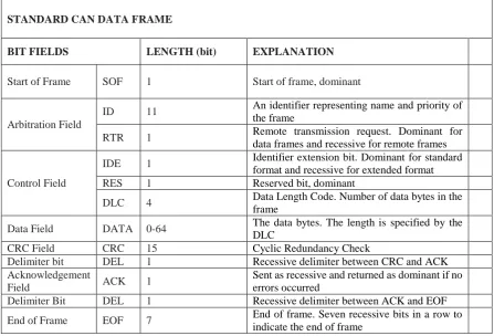
For sake of completeness of the discussion, declarations for the standard CAN Data Frame is listed in Table 1. Standard CAN Data Frame consist of different bit fields. Brief explanation for each of these bit fields is also given in Table.1. For detailed information one can refer to the sources given in references [4] [5] [6] [7].
Table 1. Standard CAN Data Frame
In DECS, Data Frame is defined by the following structure.
typedef /* [uuid] */ DECLSPEC_UUID("B268A2C4-2A2E-4c9d-804D-0B2BAB4E47C8") structtCAN
{
unsignedshort id; // can message identification (arbitration) int rtr; // remote transfer frame (firs bit in control field)
BYTE length; // length of data (last tree bits in control field)
BYTE data[8]; // data to transmit (data field) } tCAN;
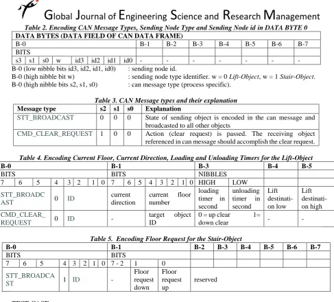
State encoding
Object state is encoded into the DATA FIELD of CAN Data Frame as indicated through Table.2 to Table.5. STANDARD CAN DATA FRAME
BIT FIELDS LENGTH (bit) EXPLANATION
Start of Frame SOF 1 Start of frame, dominant
Arbitration Field
ID 11 An identifier representing name and priority of the frame
RTR 1 Remote transmission request. Dominant for data frames and recessive for remote frames
Control Field
IDE 1 Identifier extension bit. Dominant for standard format and recessive for extended format
RES 1 Reserved bit, dominant
DLC 4 Data Length Code. Number of data bytes in the frame
Data Field DATA 0-64 The data bytes. The length is specified by the DLC
CRC Field CRC 15 Cyclic Redundancy Check
Delimiter bit DEL 1 Recessive delimiter between CRC and ACK Acknowledgement
Field ACK 1
Sent as recessive and returned as dominant if no errors occurred
Delimiter Bit DEL 1 Recessive delimiter between ACK and EOF
[Dulger* 6(2): February, 2019] ISSN 2349-4506
Impact Factor: 3.799
G
lobal
J
ournal of
E
ngineering
S
cience and
R
esearch
M
anagement
Table 2. Encoding CAN Message Types, Sending Node Type and Sending Node id in DATA BYTE 0 DATA BYTES (DATA FIELD OF CAN DATA FRAME)B-0 B-1 B-2 B-3 B-4 B-5 B-6 B-7
BITS
s3 s1 s0 w id3 id2 id1 id0 - - - -
B-0 (low nibble bits id3, id2, id1, id0) : sending node id.
B-0 (high nibble bit w) : sending node type identifier. w = 0 Lift-Object, w = 1 Stair-Object. B-0 (high nibble bits s2, s1, s0) : can message type (process specific).
Table 3. CAN Message types and their explanation Message type s2 s1 s0 Explanation
STT_BROADCAST 0 0 0 State of sending object is encoded in the can message and
broadcasted to all other objects
CMD_CLEAR_REQUEST 1 0 0 Action (clear request) is passed. The receiving object
referenced in can message should accomplish the clear request.
Table 4. Encoding Current Floor, Current Direction, Loading and Unloading Timers for the Lift-Object
B-0 B-1 B-3 B-4 B-5
BITS BITS NIBBLES
7 6 5 4 3 2 1 0 7 6 5 4 3 2 1 0 HIGH LOW
STT_BROADC
AST 0 ID
current direction
current floor number
loading timer in second
unloading timer in second Lift destinati-on low Lift destinati-on high CMD_CLEAR_
REQUEST 0 ID -
target object ID
0 = up clear 1=
down clear - -
Table 5. Encoding Floor Request for the Stair-Object
B-0 B-1 B-2 B-3 B-4 B-5 B-6 B-7
BITS BITS
7 6 5 4 3 2 1 0 7 - 2 1 0
STT_BROADCA
ST 1 ID -
Floor request down Floor request up reserved TEST CASE
A test case having four Lift-Objects and ten Stair-Objects is prepared in order to test the PSM. Requests both from stairs and inside the lifts are predefined. The case is simulated and tested on the visualising program WinEL.exe.
VISUALISING PROGRAM WINEL.EXE
Screen shots from the visualising program, WinEL.exe, for the test case above are presented through Fig.7 to Fig.10. As it is seen from these Figures, there are four separate lift dialogs each of which visualises the respective
Lift-Object. Pressing the Stair-Request-Button is simulated by entering [CTRL + nr] keys on the keyboard. Here CTRL is the control and nr is the numerical key from the keyboard. Similarly Stair-Request-Lamp is simulated by a rectangle which is placed at the right hand side of the respective stair position. Pressing the Stair-Request-Button causes the respective Stair-Request-Lamp to burn in reality. This is accomplished by red colouring of the respective rectangle in simulation.
[Dulger* 6(2): February, 2019] ISSN 2349-4506
Impact Factor: 3.799
G
lobal
J
ournal of
E
ngineering
S
cience and
R
esearch
M
anagement
from a stair, the respective direction triangle is marked with a red colour. Up request is simulated by [SHIFT + nr ] keys while down request is simulated by [CAPLOCK + nr] keys on keyboard.All requests are assumed to happen at the same instant. This is accomplished by stopping the PSM for the duration as the keyboard inputs are being made, in order to achieve the simultaneous request. PSM is stopped by turning the clock signal off. Pressing button resume/continue in the building dialog toggles the clock signal on and off.
RESULT
For the test case the initial distribution of the Lift-Objects is given in Fig.7. As seen from the Fig.7, there is no request at the initial moment. Fig.8 illustrates the various requests both from within the Lift-Objects and from the
Stair-Objects. The requests are marked with red coloured lines.
Fig.9 illustrates the intermediate positions after PSM starts to run. Similarly Fig.10 indicates final states of the
Lift-Objects together with the final states of the Stair-Objects.
[Dulger* 6(2): February, 2019] ISSN 2349-4506
Impact Factor: 3.799
G
lobal
J
ournal of
E
ngineering
S
cience and
R
esearch
M
anagement
Fig.8: Simultaneous requests at initial state of the Lift-Objects
[Dulger* 6(2): February, 2019] ISSN 2349-4506
Impact Factor: 3.799
G
lobal
J
ournal of
E
ngineering
S
cience and
R
esearch
M
anagement
Fig.10: Final states of the Lift-Objects after servicing.
CONCLUSION
Careful examination of test case reveals that the developed Process State Machine works as expected for the given initial configuration of the Lift-Objects and current request set both from lifts and building stairs. Although they are not presented in this work, many test cases are prepared and tested separately. They all proved success. Hence one can conclude that developed DECS in this study do satisfy design criterion at a large scale.
Even though a case appears, in which an incorrect result is encountered, it is possible to modify the rank() function of the ESM so that the error can be handled easily. This is actually one of the main reasons why the visualisation (simulation) of the DECS is made in this study.
PROPOSAL FOR FUTURE WORK
Development and simulation of the DECS is presented in this manuscript. Hardware implementation of the presented system can be studied as the next step in the future. In this future work, each Lift-Object and each Stair-Object can be realised in a microcontroller card together with its IO module. The already developed PSM can then be passed to the proposed hardware implementation.
ABBREVIATIONS
CCS: Centralised Control System. CPU: Central Processing Unit. PLC: Programmable Logic Control. DECS: Distributed Elevator Control System. CAN: Controller Area Network.
m: number of lifts (elevators) in DECS.
n: number of stairs in DECS.
ESM: Elevator State Machine. PSM: Process State Machine. fr: floor request.
[Dulger* 6(2): February, 2019] ISSN 2349-4506
Impact Factor: 3.799
G
lobal
J
ournal of
E
ngineering
S
cience and
R
esearch
M
anagement
cf: current floor.
rank(): rank determination function.
Lift-Object: lift object in DECS. Stair-Object: stair object in DECS. Asynchronous-IO: asynchronous input-output.
CTRL: control key.
SHFT: shift key.
CAPLOCK: caption lock key.
nr: number button.
NUM_FLOORS: number of stairs in DECS.
REFERENCES
1. Surabhi G. Pise, Omkar M. Shete, Divyani V. Shete,“A Survey Paper on Design & Control of an Elevator for Smart City Application”, International Journal of Advanced Research in Electrical, Electronics and Instrumentation Engineering (IJAREEIE), Volume 6, Issue 4, April 2017.
2. S. Huseinbegovic, S. Kreso, O.Tanovic , "Design and implementation of the CAN based elevator control system", Information, Communication and Automation Technologies, XXII International Symposium, pp.1-6, October.2009
3. B.B. Shabarinath, Nidhi Gaur, "MODBUS communication in microcontroller based elevator controller", Control Automation Robotics and Embedded Systems (CARE) 2013 International Conference on, pp. 1-5, 2013.
4. Steve Corrigan. “Introduction to the Controller Area Network”, Texas Instruments Application Report, August 2002, Revised May 2016.
5. Cook J.A., Freudenberg J. S., "Controller Area Network”, EECS 461, Fall 2008, Revised October 2013. 6. Viklander J. “Simulation of a TCU Node on a Virtual CAN Bus”, Master Thesis, Department of Physics
Umea University, January 2016.