© Shiraz University
The Experimental and Numerical Study of Hexagonal Cutting
of AISI 316L Steel Round Bars
M. Ruin Aheli, M. A. Mirzai, S. J. Hemmati
*University of Hormozgan
Abstract: Cutting processes can be used in batch production of polygonal bars with special features. In this paper, a new form of broaching process for cutting of hexagonal bars from raw round bars is discussed. Due to lack of rolled or drawn raw material, the final product is made of AISI 316L stainless steel bars having appropriate initial size. In this method, a fixed die is used as a tool, and by applying pressure to the raw bar and passing it through the die, it is cut hexagonally. To study this process, different empirical tests have been conducted with different dies. Based on the empirical data, the process is simulated by finite element method. To determine optimal features of the tool, the simulation results in the design and development (i.e., tool making) stages have been used. Among the studied rake angles, the 15 degree angle can be introduced as the most suitable rake angle. In order to evaluate the amount of work hardening, micro hardness tests have been carried out. Quality of final surfaces of machined samples in terms of material and angles of the simulated dies were acceptable and experimental measurements indicated a slight increase in micro hardness of surface layers of the samples.
Keywords: AISI 316Lstainless steel machining, Hexagonal cutting of bar, Broaching process simulation.
1. Introduction
Due to their excellent corrosion resistance, high thermal stability and non-magneticity, AISI 316L stainless steel hexagonal bars are widely used in oil and gas, food, pharmaceutics and ship building industries. Mass production of the bars is possible by forming processes such as rolling and drawing. Some of these methods require secondary heat treatments due to surface effects such as work hardening [1] which can increase the stages and costs of the process. Cutting processes can be used in batch production of these bars with given specifications. When it is necessary to machine some grooves in thick flaking parts, which necessitates high metal removal, the usual broaching process could be applied [2]. A general broaching tool is made up of a series of teeth in a row with gradually increasing size along the tool axis until the final shape is formed. The total depth of cut is divided between the rows, so that each row cuts up to few tenths of a millimeter. In broaching process, workpiece is usually fixed and the desired shape is formed by displacing of the broaching tool. The costs of tool making and repair are relatively high as well.
Bagwell and Tryles [3] used rotary broaching method to produce polygonal sections. Two essential parts of this process are the tool and its holder which produce final shape of the workpiece via crank mechanism and rotating teeth of the tool. This method is able to generate internal and external polygon forms in one pass with accuracy order of hundredths of one millimeter. For performing this process, a groove should be initially made in workpiece, so that chips are removed from the workpiece at the end of operation. This process needs devices such as turning or milling machines.
Several experimental and analytical studies have been conducted to optimize the cutting process. Lo [4] analyzed the cutting process assuming the rake angles of 0, 5, 10 and 15 degrees by using finite element method (FEM). He concluded that by increasing the angle, cutting force and maximum equivalent strain decrease and maximum loss occurs when the angle increases from 10 to 15 degrees. Shi, et al. [5] examined the effect of friction on orthogonal cutting by FEM. They considered Coulomb friction law with the friction coefficient of 0 to 0.6 and rake angles of 15° to 30° for simulation of the process. They showed that increasing the coefficient of friction under constant rake angles causes a reduction in chip curvature and increases contact length, cutting force and temperature. Also, they found that by maintaining constant friction coefficient and increasing the rake angles, cutting force and maximum temperature will be reduced.
Maranhao and Davim [6] modeled cutting of AISI316 stainless steel by FEM and showed that the coefficient of friction has an important role in chips’ formation, magnitude of cutting forces, stresses and strains. Kong, et al. [7] studied broaching performance of super alloy GH4169. This super alloy is a hard to cut material and formation of its saw-tooth chips during the high speed machining has significant impact on cutting force, cutting temperature, tool lifespan and surface uniformity of the pieces. They studied formation of saw-tooth chips in this mode by using ABAQUS finite element software and showed that by increasing the rake angle from 0⁰ to 15⁰, the saw-tooth region reduces, and almost fades at angle of 15 degrees. Satana, et al. [8] investigated the cutting speed impact on wearing of coated tungsten carbide tool while machining AISI316L steel. They could predict maximum wear of tool at different speeds by evaluating temperature and stress distributions in workpiece and tool. Their empirical findings also confirmed the validity of the predictions. Ben Moussa, et al. [9] performed numerical and experimental analyses on the distribution of residual stress and plastic strain in cutting AISI316L steel. Their results showed that work hardening occurs in surface layers of the parts. The examination of sample section by optical microscope shows change of material structure as a result of machining. The increase in cutting speed results in the increase of the surface plastic strain. Sawarkar and Boob [10] simulated the orthogonal cutting of AISI316L steel in order to determine the generated residual stress. They showed that the stresses have the maximum values in upper layers, which decrease by moving towards subsurface layers of the machined work piece. Umbrello, et al. [11] examined the influence of Johnson Cook material constants on finite element simulation of AISI316Lsteel machining. They investigated the effect of the five material constants of Johnson Cook equations for orthogonal machining on forces, temperature distribution and residual stress. They observed that all the considered process outputs, in particular residual stress, are very sensitive to material constants of Johnson Cook model.
In this paper, the hexagonal cutting of AISI316L steel round bars will be discussed by using a new form of broaching process. Following this procedure, operational variables of the new broaching process such as material and rake angle of the die are assessed. In order to improve the die performance, the effect of rake angle is studied numerically by FEM.
2. Settings of Experimental Method
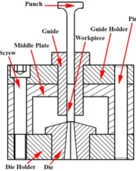
Fig. 1. Sectional view of the special tool for hexagonal cutting
As can be seen in Fig. 1, the tool is consisted of eight components including punch, guide, die, guide holder, die holder, intermediate plate, pin and screw. Required pressure for crossing of workpiece through the die is provided by connecting the punch to press arm. Guide’s duty is to direct punch and sample. Clearance between guide and sample is 0.2mm and the guide should be coaxial with the die. Hexagonal cavity of the die in which chip and clearance angles are applied has the duty of cutting raw material. Middle plate creates a suitable space for lubrication of bar and die and also provides a space to gather chips. Die and guide holders are responsible for positioning and holding the die and guide. Figure 2 shows raw bar, die and final hexagon bar, respectively. AISI 316L steel is used in this study with the grain size of approximately 50 μm and hardness of 170 HV. Tests were performed on samples with a diameter of 6 mm and a length of 3 cm. Fox cutting oil of Ecocut 832 number was applied as lubricant.
Fig. 2. (a) Raw bar, (b) Die and (c) hexagonal bar
A 25 tons servo electrical tensile-compression testing machine was used to supply power and produce workpieces. Micro hardness of machined samples was tested by Bareiss tester of V-Test model. 3D FAMILY measuring microscope of VML model was applied for color imaging of dies and samples surfaces. Also chip thickness was measured by VEGA model of scanning electron microscope (SEM) which was made by Tescan Company. Finally, machined samples were micro-threaded on lathe by using M3 thread.
Table 1. Chemical composition of AISI M42 HSS [12]
V Co W Mo Cr C Composition
1.2 8
1.5 9.4 3.9 108 Wt.%
To make a die containing such materials, first a square cross-section bit with 25 mm side length was grinded cylindrically. Then, the cylindrical part was cut from the bit by a wire cut machine. A hole was then created within the die by a 4 mm in diameter copper electrode on an electro discharge machine (EDM). The hole was machined hexagonally on wire cut machine and a 15 degree rake angle was set in the face of the die with cylindrical grinding machine. The die face roughness was 0.2 μm-Ra. Punch and guide were made of AISIO1, and were hardened to 60 and 58 HRC, respectively.
3. Settings of Numerical Method
To simulate the new broaching process, capabilities of ABAQUS finite element software and its quick mode were used. Solving nonlinear problems and issues of plastic deformation under high strain rates is possible in this mode. Since the temperature of workpieces does not show significant changes after cutting under proper lubrication, the heat generated during the cutting process and its conduction within the workpiece will be ignored. Thus, numerical simulation of chip formation in this process needs an elastic plastic analysis. Mechanical properties applied in software for AISI 316L raw bars and for AISI M42 die steel are given in Table 2.
Table 2. Properties of AISI316L (Nasr, et al., 2005) and AISI M42 [13]
Different researchers have suggested special models for flow stress in the case of large deformation and strain rates in which Johnson Cook's Eq. (1) is often used [14]:
(1)
In this relation, A is initial yield stress of the material at room temperature, B is hardening modulus, is plastic strain, is plastic strain rate and is reference plastic strain rate . The parameter n is hardening exponent, and C shows the strain rate sensitivity. Table 3 was used for the plastic properties of the material. It should be noted that in this relation due to the assumption of no change in temperature of the samples, the term related to temperature could be ignored.
For completing plastic model and predicting material rupture, damage model must also be provided. Therefore, in finite element models, the element that has critical damage loses the ability to tolerate load and is removed from model and is separated from workpiece as a chip. In this article, the damage model of Johnson Cook was used as a benchmark for chip separation [14]. Johnson and Cook provided a model in the general form of Eq. (2) in which effective fracture strain (f ) is a function of several variables:
(2)
Property AISI 316L AISI M42
Modulus of Elasticity (GPa) 193 225
Poisson’s ratio 0.285 0.285
Density (kg/m2)
is the hydrostatic component of stress, is the von Mises material flow stress and D1, D2, D3, D4 are
material constants of fracture. The essential parameters of both Eqs. (1) and (2) for AISI 316L are given in Tables 3 and 4, respectively.
Table 3. J–C parameters for AISI 316L [8]
A (MPa) B (MPa) n C
490 600 0.21 0.015 1
Table 4. Johnson-Cook fracture parameters of AISI316L [8]
D1 D2 D3 D4
0.05 3.44 2.12 0.002
To reduce solution time, by considering symmetry of the problem, only one-sixth of raw bars, die and punch were modeled as shown in Fig. 3. As it is shown in Fig. 3, the punch was only displaced in the Y direction and downward to the length of the bar and was bound in all other directions. The axis of hexagon bar was considered free in Y direction and bound in all other directions. Also, the depth of cut from hexagon bar surface was only bound in Z direction and was considered free in all other directions. Moreover, for the die, only flank and chip surfaces were considered free and the other surfaces were completely bound. In this study, all contacts were assumed as general and with a Coulomb friction.
Fig. 3. Boundary conditions
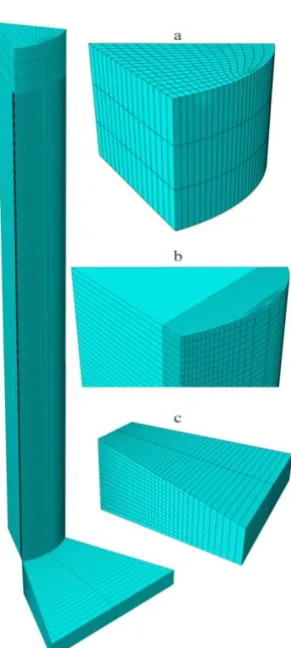
The types of grid and partitions, because of creating a direction of material flow in three-dimensional chip formation, have significant impacts on the results. Therefore, grid and partitions are selected in such a way that causes separation of elements as chips similar to ones in the experimental process. The eight node 3D element with a reduced integrated formulation (C3D8R) was used for the raw bar and die, and punch was assumed to be rigid. In Fig. 4, one-sixth of grid and partitions of punch, raw bar and die have been shown.
Fig. 4. Selected mesh grid for (a) Punch, (b) workpiece and (c) Die
4. Results and Discussion
First the die was made from AISI D3 steel with a rake angle of 10 degrees. Figure 5a shows the top view of the die cavity after running two tests. As it can be seen, die edge has been worn and some built up edge are created. Figure 5b shows a sample made with the die. Surface of the sample suggests material detachment and non-uniform removal of chip from the surface. Furthermore, when cutting the second workpiece, guide of the die was broken, which is illustrated in Fig. 6.
Fig. 5. (a) The die cavity made from AISI D3 steel, (b) Initial output sample
In this case, wearing of the die edge can be due to its low strength or hardness. Breakage of the guide in rake angle of 10 degrees can also be due to the lack of sufficient penetration of die edge in workpiece and as a result its expansion and pressure exerted on the guide from the workpiece. Because of the efficiency of numerical simulations in reducing costs and time required for studies in experimental cases, a numerical assessment of appropriate rake angle was performed. Moreover, the die material was changed to AISI M42 HSS.
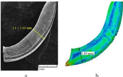
First, the die was assumed to be rigid with rake angle of 10 degrees in simulations. Figure 7 indicates the experimentally generated chip and its numerical counterpart. In this case, shape of the numerical chip is consistent with the experimental one. Experimental chip thickness was measured with SEM and numerical chip thickness was measured in ABAQUS software. The average thicknesses of the experimental and numerical chips were 1.57 and 1.61 mm, respectively. Difference of the average thicknesses was 0.04 mm that shows an error of less than 3%. Also, surface of the numerical chip was rough and suggests separation of a number of elements from the contact face of the chip, which is consistent with the experimental case, that is, the built up edge created on the die face.
Fig. 7. Comparison between experimental and numerical chip geometry: (a) experimental result using of AISI D3 die (b numerical result with μ=0.2 and rake angle=10°
To investigate the effect of friction coefficient, several simulations were conducted with different coefficients. In Fig. 8, the type of chips made in different conditions has been shown. As can be seen from this figure, by increasing the friction’s coefficient from 0.05 to 0.5, the curvature of the chips has decreased. By reducing the friction as a result of more efficient lubrication, contact length of the tool and chip becomes less and chip flow gets better and, thus, chip curvature increases. Also, it is observed that by reducing the coefficient of friction, chip thickness gets closer to the thickness of an undeformed chip. In Fig. 9, numerical chips with different frictional conditions have been visually compared with the experimental ones. Figure 10 shows formation of chip at the beginning and end of the process in the experimental and numerical modes with the coefficient of μ=0.2. Totally, shape of most of the created chips enjoys from a better compatibility with friction coefficient μ=0.2 which is consistent with the report of Miguelez, et al. [16].
the undeformed chip and there is no further roughness in the contact face. By increasing the rake angle of die to 20 degrees, it can be seen (Fig. 11d) that compared to 15 degrees angles the chip thickness got closer to the undeformed chip thickness and no roughness is seen on the chip face. Thus, material removal conditions are more favourable with rake angles of 15 and 20 degrees.
Fig. 10. Comparison chip formation at the coefficient of friction µ=0.2 (a) beginning and (b) end of cutting
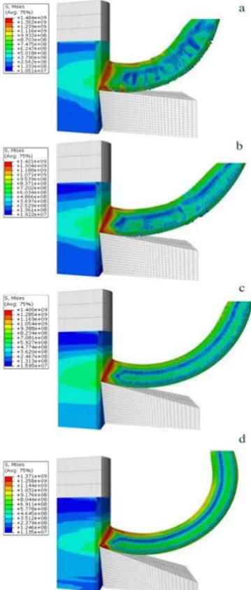
Another factor that can be helpful in determination of the appropriate rake angle is consideration of the stress distribution on the die face. If in finite element model, the die is assumed to be ductile, simulations can be repeated again for 5 to 20 degrees of rake angles. In Fig. 12, the effect of rake angles on stress distribution on the die is shown. It can be observed that by increasing the angle of the die, locality of stress distribution is increased and stress concentration moves toward the tool tip. Figure 13 shows von Mises equivalent stress generated at the cutting edge of die with the rake angles from 5 to 20 degrees. According
Fig. 8. Chip formation at various values for the coefficient of friction (a) µ=0.05, (b) µ=0.1, (c)
µ=0.2, (d) µ=0.3, (e) µ=0.4, (f) µ=0.5
Fig. 9. Comparison of chip formation at various values for the coefficient of friction (a) µ=0.05,
to this graph, stress on the cutting edge of the die with angle of 5 degrees is about 200 MPa and by increasing the rake angle to 10 and 15 degrees, the stress on the cutting edge increases to the extent that it reaches to nearly 270 MPa at rake angle of 20 degrees.
Fig. 11. The effect of rake angle on chip deformation, where the rake angle is: (a) 5°, (b) 10°, (c) 15°, (d) 20°
Fig. 12. The effect of rake angle on stress distribution on die and workpiece at rake angle of: (a) 5°, (b) 10°, (c) 15°, (d) 20°
Fig. 13. Calculated Stress in cutting edge with rake angle 5°, 10°, 15° and 20°
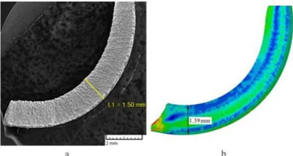
In Fig. 15, the experimental and numerical chips produced by the die of AISI M42 HSS with an angle of 15 degrees are compared with each other. Shapes of experimental and numerical chips are in good agreement. Average chip thickness measured in ABAQUS software was 1.39 mm and the average experimental chip thickness measured with SEM was 1.5mm. The difference of these thicknesses is 0.11 mm that shows an error of less than 8%. Also quality of the chip face with rake angle of 15 degrees indicates a good quality in the surface of produced workpiece and predicts lack of built up edge in the die.
Fig. 15. Comparison between experimental and numerical chip geometry: (a) experimental result using of AISI M42 die (b) numerical result with μ=0.2 and rake angle=15°
To assess the strength and hardness of the hexagon bars produced with the proposed method, micro hardness tests were conducted. For this purpose, three raw bars and three hexagon bars were tested by micro Vickers method. The tests was performed from surface toward the centre of bars with 300 gf force and 550 x magnification and a force application time of 10 sec. Table 5 gives the obtained values of micro hardness. Also in Fig. 16, the average hardness measured in hexagon bars and raw bars are compared. This figure shows that as a result of machining process, hardness of hexagon rod has increased for approximately 10% compared to the hardness of raw bars.
Table 5. Microhardness (HV) of round bar and hexagona bar
Distance from surface (mm)
0.1 0.3 0.5 1 1.5 2.5
Microhardness of Round Bar (HV)
312 302 306 309 291 270
310 300 305 295 289 270
309 302 304 303 301 285
Average 310.3 301.3 305 302.3 293.6 275
Microhardness of Hexagona Bar (HV)
352 330 336 341 341 345
328 314 313 296 297 306
345 342 341 340 325 321
Fig. 16. The average of Microhardness (HV) of round and hexagonal bar
Since after doing hexagonal cutting micro-threading work should be performed on these bars for assessing machinability, this procedure (i.e., micro threading) was carried out with M3 thread. Pitch of the threads was measured with SEM and the values are presented in Fig. 17. Also, the produced hexagon rods were measured by a Mitutoyo Micrometer with 0.01 mm resolution. Errors of face-to-face distances in the produced workpieces were in the range of 0 to -0.01 mm. The force required for feeding bar into die was about 5500 N. Also, surface roughness of the hexagon rods was 1.1 μm-Ra. Figure 18, shows examples of raw bar, hexagon bar chips generated by AISI M42 HSS die and micro-machined hexagon bars.
Fig. 17. Image of (a) micro threaded sample (b) pitch of thread
Fig. 18. Round bar, hexagonal bar made by AISI M42, hexagonal bar with micro machining
5. Summary and Conclusion
possible, and the results of hardness testes indicated an increase of about 10% hardness in surface layers of the bars. This method can be extended to other polygon bars and sections.
In order to study this method further, a number of experimental tests were performed and based on the experimental results simulations and validation of the process were carried out. Validations were performed based on the morphology of chips, the experimental measurements of chip thickness with SEM and also surface quality of chip surface. Due to the reasonable consistency of average thickness of the experimental and numerical chips as well as their predicted and obtained quality, the proposed simulation method can be used to evaluate the suitable rake angle of the die. In the conducted simulations, the role of coefficient of friction on chip formation and the effect of rake angle on stress distribution were studied. Among the studied angles, the 15 degree angle can be selected as the most suitable rake angle for the desired cutting operations.
6. References
[1] Suchy, Handbook of Die Design Fundamental, Mc Graw-Hill, New York, 1998.
[2] J. R. Paquin, R. E. Crowley, Die Design Fundamental, Industrial Press Inc, New York, 1986.
[3] P. Bagwell, J. Tryles, One-Pass Polygon, Cutting Tool Engineering Magazine 58 (3) (2006).
[4] S.P. Lo, An analysis of cutting under different rake angles using the finite element method, J. Mater. Process
Technol 105 (1-2) (2000) 143–151.
[5] G. Shi, X. Deng, C. Shet, A finite element study of the effect of friction in orthogonal metal cutting, Finite Elem.
Anal. Des. 38 (9) (2002) 863–883.
[6] C. Maranhão, J. Paulo Davim, Finite element modeling of machining of AISI 316 steel: Numerical simulation
and experimental validation, Simul. Model. Pract. Theory. 18 (2010) 139–156.
[7] X. Kong, B. Li, Z. Jin, W. Geng, Broaching performance of super alloy GH4169 based on FEM, J. Mater. Sci.
Technol. 27 (2011) 1178–1184.
[8] W. Satana, K. Tuchinda, A. Tuchindac, S. Chutima, Computational Study of the Effect of Cutting Speeds on
Tool Wear during Machining of AISI 316L Steel, Adv. Mater. Res. 622-623 (2012) 409–413.
[9] N. Ben Moussa, H. Sidhom, C. Braham, Numerical and experimental analysis of residual stress and plastic strain
distributions in machined stainless steel, Int. J. Mech. Sci. 64 (2012) 82–93.
[10]N. Sawarkar, G. Boob, Finite element based simulation of orthogonal cutting process to determine residual stress
induced, ICQUEST, (2014), 33-38.
[11]D. Umbrello, R. M’Saoubi, J.C. Outeiro, The influence of Johnson-Cook material constants on finite element
simulation of machining of AISI 316L steel, Int. J. Mach. Tools Manuf. 47 (2007) 462–470.
[12]N. Camuşcu, E. Aslan, A comparative study on cutting tool performance in end milling of AISI D3 tool steel, J.
Mater. Process. Technol. 170 (2005) 121–126.
[13]M.N.A. Nasr, E.G. Ng, M.A. Elbestawi, Modeling the effects of tool-edge radius on residual stresses when
orthogonal cutting AISI 316L, Int. J. Mach. Tools Manuf. 47 (2007) 401–411.
[14]Erasteel, High Speed Steel. http://www.erasteel.com/,visited on 15.02.2015.
[15]T. Mabrouki, J.F. Rigal, A contribution to a qualitative understanding of thermo-mechanical effects during chip
formation in hard turning, J. Mater. Process. Technol. 176 (2006) 214–221.
[16]M.H. Miguélez, R. Zaera, A. Molinari, R. Cheriguene, A. Rusinek, Residual stresses in orthogonal cutting of
metals: the effect of thermo mechanical coupling parameters and of friction, J. Therm. Stress. 32 (2009) 269–
![Table 2. Properties of AISI316L (Nasr, et al., 2005) and AISI M42 [13]](https://thumb-us.123doks.com/thumbv2/123dok_us/8956076.1865444/4.595.166.418.83.158/table-properties-aisi-l-nasr-et-al-aisi.webp)
![Table 3. J–C parameters for AISI 316L [8]](https://thumb-us.123doks.com/thumbv2/123dok_us/8956076.1865444/5.595.163.423.144.275/table-parameters-for-aisi-l.webp)