U D K 621.822.8:539.5:539.3:519.65
Odvisnost oblike in velikosti stičnih površin od obremenitve in lastnosti
materialov
Dependence of Shape and Size of Contact Area of Load and Material
Properties
KATARINA DROBNIČ - IVAN PREBIL - MATJAŽ TORKAR
V p risp evk u j e obravnavan p ro b le m stika kotalnega elem enta in tečine p r i d oločanju nosilnosti kota ln ih le ža jev velikih dim enzij. N o siln o st j e d o lo čen a z največjo d o p u stn o stič n o silo na najb o lj o b r e m e n je n e m k o ta ln e m e le m e n tu . U v e lja v lje n a k r ite r ija , k i d o lo č a ta d o p u s tn o s ta tič n o o b re m en ite v n a k o ta ln i e le m e n t - k rite r ij d o p u stn e p la s tič n e d e fo rm a c ije in k r ite r ij d o p u stn e p o d p o v r š in s k e n a p e to sti n a m e ji ka ljen e p la s ti - p o d a ja ta vrednosti, k i se m e d se b o j m očno razlikujejo. Z nam enom , da bi u g o to v ili dejansko n o siln o st p o v ršin sk o kaljen ih k o ta ln ih ležajev, so bile izvedene m eritve na le ža jn ih obročih. K rivulji, ki p o v e z u je ta veliko sti stične p o v ršin e in skupne defo rm a cije teles v stiku, k a žeta zn a čiln o ela sto -p la stičn o obna ša n je m ateriala. N a p o d la g i teh k r iv u lj j e z a r a z lič n e p r im e r e k o ta ln e g a s tik a m o g o č e d o lo č iti o d v is n o s t d o p u s tn e sta tič n e o b rem enitve o d vrste m ateriala, d eb elin e in trdote utrjene p la s ti na p o v r š in i tečine ter g eo m etrijske o blike stičn ih p o vršin .
The p a p e r d e a ls w ith the p r o b le m o f the co n ta ct b etw een the ro llin g elem e n t a n d the racew ay, a p p ea rin g in the ca lcu la tio n s o f the ca rryin g ca p a city o f large d im en sio n ro llin g bearings. The ca rryin g ca p a city is sp e c ifie d b y the la rg est a llo w e d co n ta ct fo r c e on the ro llin g elem e n t w ith the h ig h e st load. The e sta b lish e d criteria f o r the determ in a tio n o f the m axim um a llo w e d sta tic lo a d o f a ro llin g elem e n t - the criterio n o f p e rm issib le p la s tic d efo rm a tio n a n d c riterio n o f p e rm issib le subsu rfa ce stress o n the b o u n d a ry o f the h a rd e n e d layer - va ry widely. We have m ade the m ea su re m ents o f b e a rin g rin g s in o rd er to f i n d o u t the a ctu a l ca rryin g ca p a city o f the b ea rin g s w ith h a rd e n e d surfaces. The cu rves sh o w in g the co n ta ct surface size a n d the d efo rm a tio n o f bodies in co n ta ct as a fu n c tio n o f the a p p lie d fo r c e sh o w the fa m ilia r ela stic-p la stic m a te ria l behaviour. These curves are the basis f o r the d eterm in a tio n o f a p e rm issib le sta tic lo a d as a fu n c tio n o f the m aterial, thickn ess a n d ha rd n ess o f the h a rd e n e d layer, a n d g e o m e try o f the b o dies in contact.
0 UVOD 0 INTRODUCTION
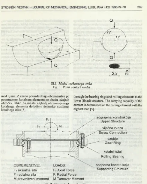
Osnovna teorija stika dveh teles v dotiku je bila postavljena že leta 1881 [1], Po tej Hertzovi teoriji, ki je omejena na idealno elastični telesi in dotik brez trenja (sl. 1 ), so bili z razvojem mehanike v 20. stoletju postavljeni za potrebe hitro razvijajoče se industrije in transporta številni uporabni modeli [2], [3] in [4], V nadaljevanju prispevka se bomo omejili na problem stika dveh teles pri vrtljivi zvezi.
Vrtljiva zveza j e kompleksen strojni sestav, ki omogoča vrtenje ali samo nihajoče gibanje dveh konstrukcijskih sklopov. Osnovni elementi vrtljive zveze so kotalni ležaj, ki omogoča relativno vrtenje, vijačna zveza, ki veže obroča ležaja s podporno konstrukcijo in nadgradnjo, in pogosto še ozobje, kije integrirano na zunanjem ali notranjem obroču ležaja in je namenjeno za pogon vrtilnega gibanja konstrukcije (sl. 2). Prenos kombinacije zunanje obremenitve iz nadgradnje na podporno konstrukcijo poteka prek ležajnih obročev in kotalnih elementov
The basic theory of two bodies in contact was set up already in 1881 [1], This Hertz theory which is limited to ideally elastic bodies (Fig. 1), and no fric tion in contact, has been the basis for several suc cessful models developed in the 20th century [2], [3] and [4] to comply with the needs of fast industrial and transport development. In the paper we shall con sider the contact of two bodies in a rotational con nection.
Q
Sl. 1. Model točkovnega stika Fig. 1. Point contact model
med njima. Z znano porazdelitvijo obremenitve po posameznem kotalnem elementu po obodu ležajnih obročev lahko na mestu najbolj obremenjenega kotalnega elementa določimo dejansko nosilnost kotalnega stika [5],
through the bearing rings and rolling elements to the lower (fixed) structure. The carrying capacity of the contact is determined on the rolling element with the highest load [5],
nadgrajena konstrukcija Upper Structure
OBREMENITVE: F a aksialna sila F r radialna sila
M prevrnitveni moment
F a Axial Force F r Radial Force M Turnover Moment
vijačna zveza Screw Connection
oz obje Gear Ring kotalni ležaj Rolling Bearing podporna konstrukcija
Supporting Structure
SI. 2. Osnovni elementi vrtljive zveze Fig. 2. Basic elements o f a rotational connection
1 KRITERIJA STATIČNE NOSILNOSTI KOTALNEGA STIKA
1 CRITERIA OF STATIC CARRYING CAPACITY OF A ROLLING CONTACT
Poškodbe, ki se pojavljajo pri velikih počasi tekočih ležajih, so v večini primerov odvisne od velikosti statične obremenitve in utrujanja materiala. Zaradi prevelikih statičnih obremenitev v mirovanju se pojavijo plastične deformacije teles v stiku, zlasti
na tečini, ki ne omogočajo več enakomernega gibanja kotalnega ležaja. Tehnologija izdelave vrtljive zveze zahteva uporabo mehkih jeklenih materialov, ki se dobro mehansko obdelujejo, surovi pa nimajo potrebne površinske nosilnosti in odpornosti proti vtiskovanju. Ustrezno nosilnost tečine dosežemo s površinskim kaljenjem. Poškodbe, ki se pojavijo zaradi preplitvo kaljenih ležajnih tečin, se kažejo z razpokami v osnovnem materialu pod utrjeno plastjo in se širijo proti površini tečine. Z namenom, da bi zagotovili normalno delovanje kotalnega ležaja vrtljive zveze v času predpisane dobe trajanja, sta se za določitev dopustne statične nosilnosti uveljavila naslednja kriterija: kriterij dopustne plastične deformacije in kriterij dopustne podpovršinske napetosti na meji kaljene plasti.
1.1 Kriterij dopustne plastične deformacije
Trajna plastična deformacija v stiku dveh teles (kotalni element, tečina) se pojavi pri preobremenitvi na manj nosilnem elementu stika. V praksi se pojavljajo lokalne plastične deformacije na površini tečine že pri manjših obremenitvah, in sicer zaradi realne hrapavosti površine. Na vrhovih neravnin je dejanska napetost večja od elastične meje materiala, posledica tega je plastična izravnava hrapavih stičnih površin. Vpliv lokalnih preobremenitev in z njimi povezanimi mikroplastifikacijami je pri obravnavi statične nosilnosti kotalnega stika zanemarljiv [6].
Poglavitna dopustna velikost statične obremenitve prekaljenih ležajnih obročev je na mirujočem ležaju, to je na njegovem najbolj obremenjenem kotalnem elementu, določena z obremenitvijo [7], pri kateri se pojavi v stiku trajna plastična deformacija velikosti 0,01% premera kotalnega elementa:
consequently the movement of the rotational connec tion becomes uneven. The material for rotational bear ings must be sufficiently soft to facilitate the manu facturing process. This material does not have the surface carrying capacity and strength to prevent the impressions. The surface carrying capacity is in creased by suitable heat treatment, i.e. hardening of the raceway. The cracks appearing in the base ma terial under the hardened layer and growing toward the surface are typical of bearings with insufficient hardened layer thickness, and are caused by exces sive subsurface stresses. Two criteria have been established to evaluate the static carrying capacity of a rotational connection: criterion of allowed per manent deformation, and criterion of allowed shear stress on the edge of the hardened layer.
1.1 Criterion of allowed permanent deformation
Permanent plastic deformation in the contact of two bodies (rolling element and raceway) appears on the weaker contact body when overloaded. Plas tic deformations appear already with relatively small loads, because of the rough surface. On the surface peaks the stress are larger than computed, so the microlocations in the contact are overloaded, caus ing a plastic smoothening of rough surfaces. The in fluence of local overloads and consequent plastic de formations can be neglected in the calculations of the rotational connections [6],
The basic permissible static load on the non moving bearing, i.e., on the rolling element with the highest load, equals the load causing permanent de formation of 0.01% of the rolling element diameter in the contact [7]:
(1).
Plastična deformacija takšne velikosti še zagotavlja miren tek kotalnega ležaja brez vibracij in je bila privzeta tudi v trenutno veljavnem mednarodnem standardu [8]. Na temelju preizkusov je bil razvit računski postopek [9], ki določa največjo statično obremenitev na najbolj obremenjenem kotalnem elementu za jeklene prekaljene ležaje s površinsko trdoto med 63,5 in 65 HRc. Za točkovni stik (kroglični kotalni element), je največja dopustna statična obremenitev določena z izrazom:
2 8 d 2 Qa" " g ( p )
za linijski (valjasti kotalni element) pa:
This size of plastic deformation guarantees smooth vibrationless running of a bearing, and has been adopted in the current international standard [8]. The computational procedure [9] for the determina tion of the highest load on the rolling element of a steel bearing with raceway hardness between 63,5 and 65 HRc has been developed on the basis of ex perimental data. For the point contact (ball rolling el ement) the maximum permissible static load equals:
(104 - ^ ) "
d
and for the line (cylindrical rolling element):
Qall
3 1 0 d l ef g ( p )
(104 % ) 3
d
V izrazih (2) in (3) popisuje funkcija g (p) geometrijsko obliko teles v stiku, potenca n pa je odvisna od razmerja velikosti kotalnega elementa in tečine in je za vrednosti med 0,92 in 0,97 enaka 0,5
[10].
1.2 Kriterij dopustne podpovršinske napetosti na meji kaljene plasti
In expressions (2) and (3) g (p) is a function of the geometry of the bodies in contact and exponent n
is a function of the size ratio of ball and raceway, and equals 0.5 at values between 0.92 and 0.97 [10].
1.2 Criterion of permissible shear stresses on the limit of the hardened layer
Kriterij, ki temelj i na zahtevi po ustrezni debelini in trdoti kaljene površinske plasti, pravi [11], da se poškodbe ne bodo pojavile, če prim erjalna podpovršinska napetost po hipotezi največjih strižnih napetosti na meji kaljene plasti in osnovnega materiala ne bo presegla meje elastičnosti osnovnega materiala. Porazdelitev primerjalne napetosti pod površino mora biti takšna, daje njena največja vrednost v območju kaljene plasti, vrednost na meji kaljene plasti pa manjša ali enaka proporcionalni meji elastičnosti osnovnega materiala (sl. 3a):
The criterion based on the required thickness and hardness of the hardened layer states [11] that damage will not occur if the subsurface stress (cal culated using the hypothesis of maximum shear stresses) does not exceed the elasticity limit of the base material. The distribution of the stress must have its maximum in the hardened layer, and the value on the hardened layer boundary must be equal to or less than the elasticity limit ofthe base material (Fig. 3a):
(4). c r fp r i / at 50HRc) < cr0 2
SI. 3. Shematski prikaz kriterija dopustne strižne napetosti na meji kaljene plasti a) porazdelitev napetosti pod površino, b) določitev debeline kaljene plasti Fig. 3. Schematic illustration o f the criterion o f permissible shear stress on the surface
o f the hardened layer
a) stress distribution under the surface, b) determination o f the hardened layer thickness
Meja kaljene plasti je določena z razdaljo od površine, na kateri trdota kaljene plasti ne pade pod vrednost 50 HRc (sl. 3b). Meja elastičnosti osnovnega materiala se določi na globini trikratne debeline kaljene plasti.
2 PREIZKUŠANJE 2.1 Izbira preizkušancev
Material za preizkušance je bil določen po obstoječi maloserijski proizvodnji velikih ležajev. Zaradi tehnologije izdelave, to je valjanja ali krivljenja jeklenih gredic in varjenja v obroč ter mehanske
The boundary ofthe hardened layer is defined by the distance from the surface, where the hard ness of the layer falls to 50 HRc (Fig. 3b). The elas ticity limit is determined at a depth of three times the thickness of the hardened layer.
2 TESTING
2.1 The choice of test specimen
and machining of the raceway, making of gearing and fixing holes - low carbon steel C45, and steel alloy 42CrMo4 were chosen. The basic property of both steels in the normalized state is a soft ferrite- cementite micro structure (Fig. 4a, b) which is easy to machine, but has neither wear resistance not re sistance against impact. The surface of the raceway was hardened using local heat treatment. The induc tively hardened upper surface of the raceway with its fine grained martensitic structure (Fig. 5a, b) has a higher hardness and resistance against the impact of the rolling element.
SI. 4. Mikrostruktur a normaliziranega materiala: a) C45, b) 42CrMo4 Fig. 4. Microstructure o f normalized steel: a) C45, b) 42CrMo4
SI. 5. Mikrostruktura zakaljenega materiala: a) C45, b) 42CrMo4 Fig. 5. Microstructure o f hardened steel: a) C45, b) 42CrMo4
2.2 Potek meritev
Za določevanje odvisnosti deformacije stika od vzpostavljene sile na kotalni element je bilo narejeno namensko preizkuševališče (sl. 6). Z mehanskim delom, ki zagotavlja osnosimetrično obremenjevanje teles v stiku, in merilnim delom smo spremljali odvisnost deformacije stika od velikosti sile. Merjenje obremenitve in deformacije je potekalo hkrati s preizkušanjem po vnaprej določenem časovnem programu obremenjevanja in razbremenjevanja. Plastična deformacija stika je bila določena iz relativne razlike začetne in končne poti merilnika pomikov. Velikost stične površine je bila določena po končni razbremenitvi. Pri tem je bila uporabljena metoda z
2.2 Measurement procedure
A dedicated test stand was made to determine the contact deformation as a function of the force on the rolling element (Fig. 6). The mechanical part ena bling the axis-symmetric loading of bodies in contact, and the measuring part were used to monitor the con tact deformation as a function of the force. The meas urement of the load and deformation was made si multaneous with the testing according to the prede termined program of loading and unloading. The plas tic deformation was determined from the relative dif ference of the initial and final positions of the dis placement transducer. After the unloading, the size of the contact surface was measured. Here the obdelave tečine, ozobja in pritrdilnih izvrtin, sta bili
h id ra v lič n a s t is k a ln ic a
H y d r a u lic P r e s s
p r e iz k u š a n e c
m e r je n je d e f o r m a c ije
D e f o r m a tio n M e a s u r e m e n t
Sl. 6. Preizkuševališče Fig. 6. Test stand
indikatorskim sredstvom, ki vsebuje mikronske trde delce [12]. Mikropoškodbe površine zaradi vtisnjenih delcev ne vplivajo na poškodbe stika zaradi obremenitve. Zaradi drugačnega odboja svetlobe od površine omogočajo določitev velikosti stične površine tudi pri obremenjevanju v elastičnem področju materiala teles v stiku (sl. 7a, b).
indicator medium containing micrometrie hard particles was used [12]. The microscopic damage made with impressed particles does not affect the contact damage caused by loading. The different light reflection enables the determination of the size of the contact surface even when the loading is within the elastic range of the material of the bodies in contact (Fig. 7a, b).
le ž a jn a k r o g lic a R o llin g B a ll
te e m a
R a c e w a y
in d ik a to r s k a p a s ta
P a s te w ith H a rd P a r tic le s
a)
SI. 7. Merjenje velikosti stične površine: a) metoda, b) fotografija odtiska
Fig. 7. Measurement o f the size o f the contact surface: a) method, b) impression photograph
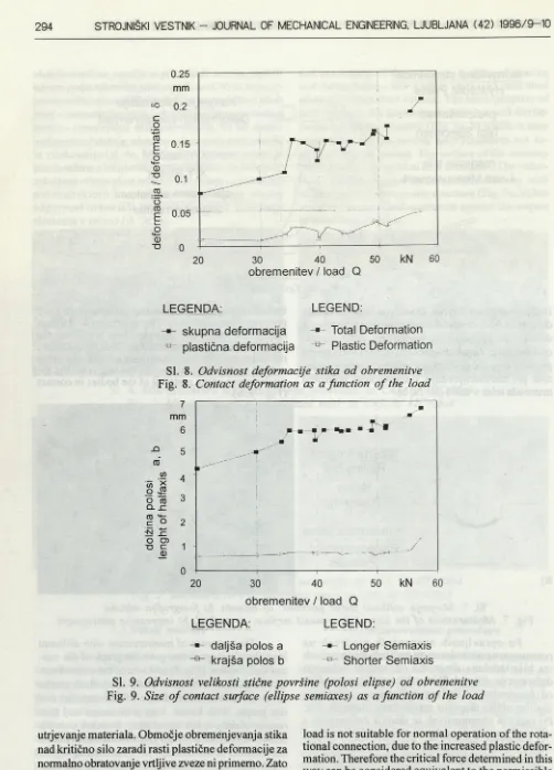
Po opravljenih zaporednih meritvah na posameznem preizkušancu pri različnih obremenitvah sta bila izdelana diagrama odvisnosti velikosti deformacije stika (sl. 8) in velikosti stične površine od obremenitve (sl. 9). Iz obeh diagramov je razvidna značilna oblika diagrama preizkušanja materiala a s . Pri manjših obremenitvah se skupna deformacija s silo zvečuje in se po razbremenitvi v celoti povrne v začetno stanje. Preseganje elastične meje materiala se kaže z zvečevanjem plastične deformacije stika. V območju utrjevanja m ateriala je plastična deformacija bolj ali manj enaka, nato pa se začne progresivno zvečevati.
Po obeh diagramih za posamezni preizkušanec smo določili kritično silo, to je silo, pri kateri se začne
The sequence of measurement with different loads on a test specimen gave the graph of the con tact deformation (Fig. 8) and size of the contact sur face (Fig. 9) as a function of the load. Both graphs show the characteristic shape of the material a s test graph. With lower load it increases and then returns exactly to the initial state. Increase over the elastic limit of the material gives an increased plastic deformation of the contact. In the hardening region of the material the deformation remains basically sta ble, then it increases progressively.
L E G E N D A : L E G E N D :
s k u p n a d e fo rm a c ija Total D e fo rm a tio n
- s - p la s tič n a d e fo rm a c ija P la s tic D e fo rm a tio n
Sl. 8. O dvisnost deform acije stik a o d obrem enitve
F ig. 8. C ontact deform ation as a fu n c tio n o f the load
n re
w </> * o JS
0 to Q . S Z 1 O
ic O 05 TD C
(D
L E G E N D A : L E G E N D :
d a ljš a p o lo s a L o n g e r S e m ia x is
k ra jš a p o lo s b S h o rte r S e m ia x is
SI. 9. O dvisnost velikosti stične p o v ršin e (poiosi elipse) o d obrem enitve
Fig. 9. Size o f contact surface (ellipse sem iaxes) as a fu n c tio n o f the load
utrjevanje materiala. Območje obremenjevanja stika nad kritično silo zaradi rasti plastične deformacije za normalno obratovanje vrtljive zveze ni primemo. Zato lahko tako določeno kritično silo enačimo z dopustno silo kriterijev za določitev statične nosilnosti kotalnega stika pri enakih geometrijskih in materialnih lastnostih teles v stiku.
3 NUMERIČNA OBDELAVA REZULTATOV
3 NUMERICAL PROCESSING OF THE RESULTS
Vsak prim er preizkušanja pri določeni obremenitvi je določen z vektorjem podatkov o materialu tečine: (E - elastični modul, v- Poissonov koeficient, <jq - proporcionalna meja elastičnosti);
rezultatu toplotne obdelave tečine (HV- trdota na površini po Vickersu, h - globina kaljene plasti); geometrijski obliki teles v stiku (d - premer kotalnega elementa, S - razmerje velikosti kotalnega elementa in tečine, k- razmerje velikosti polosi stične elipse) in obremenitve ( 0 . Rezultat preizkušanja je funkcija velikosti daljše polosi stične elipse v odvisnosti od naštetih parametrov:
<* = M Q ,E , u ,a 0 2
Pri tem je treba določiti mejo veljavnosti izraza (5). Za nas je zanimivo območje obremenjevanja do rasti plastične deformacije, to je kritične sile, ki je odvisna od parametrov materiala in geometrijske oblike stika:
Q k r ~ M E , V , < J Q j
Each test case using a particular load is deter mined with a vector of raceway material data: (E -elastic modulus, v- Poisson ratio, a02- elastic limit), result of the raceway heat treatment {HV - hardness according to Vickers, h - thickness of the hardened layer), geometry of bodies in contact {d - diameter of the rolling element, S - ratio of the sizes of the roll ing element and the raceway, k - ratio of the contact ellipse semiaxes), and the load ( 0 . The result of the testing is the size of the larger semiaxis of the con tact ellipse as a function of the above mentioned pa rameters:
H V ,h ,d ,S ,k ) (5).
Here the validity limits of the expression (5) must be defined. The relevant load range is up to the intensive increase of the plastic deformation, i.e. the critical force, that depends on the material param eters and the contact geometry:
H V ,h ,d ,S ,k) (6).
Tako določena kritična sila določa zgornjo mejo veljavnosti izraza (5).
Avtomatsko iskanje numerične zakonitosti in hkratno ocenjevanje značilnosti približka s statističnima kriterijema korelacijskega koeficienta in standardiziranega odstopanja omogoča programski sistem GoldHom [13], Splošna matematična oblika funkcijskih odvisnosti velikosti stične površine in velikosti kritične sile Y je bila produkt potenciranih vrednosti spremenljivk stikaX.al :
The critical force determined in this way yields the upper limit of the validity of the expression (5).
Automatic determination of the functional de pendence, and the estimation of the significance of the estimated value using the statistical criteria of cor relation coefficient and the standardized deviation was made using the program system GoldHom [13], The general form of the functions of the contact surface size and the critical force Y was the product of the exponential variables of the contact X. ai :
( 7 ) .
? = c [ l W )
Numerično določena približka v željeni formalni obliki, ki vsebujeta vse navedene spremenljivke kotalnega stika v normirani obliki sta:
Numerically determined estimates in the for mulation include all described variables of rolling con tact:
/ r ) a = e-4.504
f \ -1 .7 * 1 0 '
\ E J
. 20.359
0.2 k CT0.2/7 7
HV
\ 0.018 -0 .0 3 9
f j \ 13 045
H V J and
-11.181 ; 0.573 ^ 0 . 2 8 6
y d j k Q° (8)
m
( c.V 0 05V A E v
U J
V-E,,/-9.7*10 15 f X -3.645 /
<7n .
k T) in /
/ i f t j e variaj))^ W ìjiàìised y^Jpe^re :
če so vrednosti normiranih spremenljivk:
En = 2 .\* \0 5N / mm2
K, = 03
cr02„ = 300N / mm2 HVn = 517 (= 50 HRc)
d„ = 20 mm
Izraz za določitev kritične sile (9) s korelacijskim koeficientom 0,83 ni najbolje ocenjen. Vzrok je v sorazmerno majhnem številu meritev glede na raznolikost podatkov kaljenja. Izraz za določitev velikosti stične površine (8) je z vrednostjo korekcijskega koeficienta 0,95 zelo sprejemljiv. Vpliv normiranih spremenljivk elastičnega modula in Poissonovega koeficienta je v doslej izpeljanih preizkusih neznačilen, ker je bil v preizkusih uporabljeni material le jeklo ( E ~ E^; v - v). Relativno odstopanje s približkom izračunanih vrednosti od meritev je v večini primerov med 5 % in 10 % (sl. 10).
The expression for the critical force (9), has a correlation coefficient of 0.83, which is not very high. The cause lies in the relatively small number of meas urements, considering the diversity of the hardening data. The expression for the determination of the contact surface size (8) with a correlation coefficient of 0.95 is quite acceptable. The influence of the nor malized variables of the elastic modulus and Poisson ratio has been insignificant in the tests made so far, because the material used has always been steel (E ~ E ; v - v). Relative deviation of the estimated values from tfie measurements is mostly between 5 % and 10% (Fig. 10).
"O
št. meritve / No. of measurement i
CD 0
> ro o
ro j*:
CO
Q.
CO
c co c > 0
0
LEGENDA:
■
izmerjena vrednost a
približek a
relativna napaka
LEGEND:
•
Measured Value of a
-e - Calculated Value of a
Relative Error
4 SKLEP
Dobljeni rezultati pomenijo začetek obsežnejših meritev in potrditev primernosti iskanja preprostejših poti za določevanje statične nosilnosti kotalnega stika s pomočjo eksperimentalno določenih enačb. Pri tem je treba poudariti namen uporabe rezultatov meritev. V našem primeru se želimo izogniti numerično in matematično zahtevnim preračunom mehanike stika, pa tudi zajeti vse bistvene lastnosti materiala in geometrijske oblike površinsko kaljene tečine vrtljive zveze.
Oba omenjena in že uveljavljena kriterija za določitev statične nosilnosti kotalnega stika veljata pri določenih pogojih, ki pa v našem primeru niso izpolnjeni v celoti. Kriterij dopustne trajne deformacije, ki predpostavlja prekaljeni prerez jeklenega ležajnega obroča, zahteva izredno visoko površinsko trdoto (nad 63 HRc), širi uporabno področje materiala tudi nad elastično mejo in omogoča splošno obravnavo geometrijske oblike teles v stiku, ima svojo pomanjkljivost v neupoštevanju slabše zakaljene tečine (mehkejša površina, neprekaljenost) in zaradi tega spremembo mehanskih lastnosti materiala z globino na meji kaljene plasti in osnovnega materiala.
Kriterij dopustne strižne napetosti na meji kaljene plasti upošteva spremembo mehanskih lastnosti materiala z globino, posredno z določitvijo meje kaljene plasti, kakor tudi splošen geometrijski model teles v stiku. Glavna pomanjkljivost tega kriterijaje v omejitvi izračuna podpovršinskih napetosti po Hertzu, to je v elastičnem območju m ateriala in s tem neupoštevanjem plastičnega utrjevanja materiala.
V prispevku opisan postopek določevanja dopustne statične sile kotalnega stika zajema vpliv plastičnega utrjevanja materiala, saj je meja kritičnega obrem enjevanja določena z rastjo plastične deformacije. Lastnosti osnovnega materiala so popisane z mejo elastičnosti, elastičnim modulom in Poissonovim koeficientom, medtem koje kakovost površinskega kaljenja ovrednotena z debelino kaljene plasti in trdoto na površini. Popis geometrijske oblike stika je prilagojen geometrijski obliki naleganja kotalnega elementa - kroglice in ležajne tečine (konveksno - konkavno). Premer kotalnega elementa, njegovo prilagajanje tečini in razmerje polosi velikosti stične elipse opisujejo geometrijsko obliko stika v celoti.
Poleg samega določanja nosilnosti kotalnega stika in velikosti stične površine so hkrati s pripravo preizkušancev potekale tudi raziskave optimalnih parametrov indukcijskega kaljenja, ki zagotavljajo dovolj trde in debele kaljene plasti.
4 CONCLUSION
The results represent the beginning of com prehensive measurements. They confirm the deci sion to look for simpler ways o f determining the static carrying capacity o f the rolling contact with experimentally determined equations. The purpose o f the measurements is to avoid complex math ematical and numerical calculations o f the contact mechanics, and to retain all the relevant material and geometric properties o f the surface hardened rotational connection raceway.
Both criteria mentioned are valid for certain conditions, which are not completely met in our case. The criterion of permissible permanent deformation supposes a completely hardened section of the steel raceway ring, and requires a very high surface hard ness (over 63 HRc). It extends the usable range of the material over the elastic limit, and can be used to investigate the general contact of two bodies. It can not account for lower quality hardening of the raceway (softer surface, uneven hardening in sec tion), and the change in mechanical properties with depth, especially on the boundary of the hardened layer and the base material.
The criterion of the permissible shear stress on the boundary of the hardened layer indirectly takes into account the change in mechanical properties with the depth by determination of the hardened layer limit, and the general geometric model of the bodies in con tact. The main drawback of this criterion is the limi tation of the computation of the subsurface stresses according to Hertz, i.e. in the elastic range of the material, and consequently the failure to account for the plastic material hardening.
The procedure for the determination of the per missible static force of the rolling contact described in the article takes into account the influence of the plastic material hardening, because the critical load limit is determined by the increase the plastic defor mation. The base material properties are described by the elasticity limit, elastic modulus, and Poisson’s ratio; the quality of the surface hardening is evalu ated by the hardened layer thickness, and the hard ness of the surface. The contact geometry descrip tion follows closely the geometry of the contact of the rolling elem ent - the ball and the raceway (convex - concave). The diameter of the rolling el ement, its osculation, and the ratio of the contact el lipse axes complete the geometric description of the contact.
5 LITERATURA 5 REFERENCES
[1] Hertz, H.: Über die Berührung fester elastischer Körper. Journal für die reine und angewandte Mathematik, Leipzig, 1881,156-171.
[2] Lundberg, G.- Sjovall, H.: Stresses and deformation in elastic contacts. Chalmers University of Technol ogy, Gothenburg, 1958.
[3] Gupta, P. K.,Walowit, J. A.: Contact stresses between an elastic cylinder and a layered elastic solid. Transac tions of ASME. Journal of lubrication technology, 1974,250-257.
[4] Thomas, H. R.,Hoersch, V. A.: Stresses due to the pressure of one elastic solid upon another. University of Illinois, Bull. 212,1930.
[5] Prebil, L, Zupan, S., Lučič, P.: Lastverteilung auf Wälzkörper von Drehverbindungen, Konstruktion 47,1995, 345-350.
[6] Palmgren, A.: Ball and rolling bearing engineering, 3rd Ed., Burbank, Philadelphia, 1959.
[7] Harris, T. A.: 1991, Rolling bearing analysis, 3rd Edition, John Wiley & Sons Inc., New York, 1991. [8] ISO 76. Rolling bearings - static load ratings, 1987.
[9] Yhland, E.: Static load carrying capacity. Ball bearing journal, Vol.211,1982.
[ 10] Eschman, P.,Hasbargen, L.-Weigand, K.: Ball and roller bearings. John Wiley & Sons Inc., New York, 1985. [11] Pallini, R. A.,Sague, J. E.: Computing core-yield limits for case-hardened rolling bearings. ASLE Trans., Vol.28, No.l, 1985,91-96.
[12] Grabec, L,Prebil, L: Postopek ugotavljanja naleganja stičnih površin. Patent No. 9200323, Ljubljana, 1994. [13] Križman, V.: Obravnavanje šumnih podatkov pri avtomatskem modeliranju dinamičnih sistemov. Magistrsko delo. Fakulteta za elektrotehniko in računalništvo, Ljubljana, 1993.
Naslovi avtorjev: mag. Katarina Drobnič, dipl.inž. MGA, Savinjska c. 30,3331 Nazarje prof.dr. Ivan Prebil, dipl. inž. Fakulteta za strojništvo Aškerčeva 6,1000 Ljubljana dr. Matjaž Torkar, dipl. inž. Inštitut za materiale in tehnologije Lepi pot 11,1000 Ljubljana
Authors' Addresses: Mag. Katarina Drobnič, Dipl. Ing. MGA, Savinjska c. 30,3331 Nazarje Prof. Dr. Ivan Prebil, Dipl. Ing.
Faculty of Mechanical Engineering Aškerčeva 6,1000 Ljubljana Dr. Matjaž Torkar, Dipl. Inž. Institute of Metals and Technology Lepi pot 11,1000 Ljubljana, Slovenia
Prejeto: