Strojniški vestnik - Journal of Mechanical Engineering 53(2007)11, 742-746 U D K -U D C 621.941
Kratki znanstveni prispevek - Short scientific paper (1.03)
Preizkusna raziskava sinhronizacije dvovretenske stružnice
Experimental Investigation into the Synchronization of a Double-Spindle Lathe
Jan Kosm ol1 - K rzysztof Lehrich1 - Robert JastrzQbski2
('Silesian University o f Technology, Gliwice, Poland; 2Machine Tool Research and Design Centre, Pruszków, Poland)
V prispevku so prikazani rezultati preizkusne raziskave stružnice VENUS 350, izdelane v CBKO iz Pruszkowa (Poljska). RK stružnica je opremljena z dvema vretenoma. Merili smo vrtilne hitrosti obeh vreten, sinhronizacijo napake in pogonske navore motorjev, glavnega in nasprotnega. To omogoča ovrednotenje postopka sinhronizacije.
O 2007 Strojniški vestnik. V se pravice pridržane.
(Ključne besede: RK stružnice, sinhronizacija, vrtilne hitrosti, servopogoni, pogonski navor)
In this paper we show the results ofan experimental investigation ofa VENUS 350 lathe, manufacture by CBKO in Pruszkow, Poland. This CNC lathe is equipped with two spindles. We have measured the rotational speeds o f both spindles, the synchronization error and the driven moments o f the motors, main and opposite. With this information it was possible to evaluate the process o f synchronization.
© 2007 Journal o f Mechanical Engineering. All rights reserved.
(Keywords: CN C lathe, synchronization, rotational speeds, servo-drives, moment of inertia)
0 INTRODUCTION
M o d e rn C N C la th e s are v e ry o fte n equipped with two spindles: the m ain spindle and the opposite spindle. Such a feature should make com plete machining possible, as it m eans being able to m achine first on the right-hand side o f the w orkpiece and then on the left-hand side o f the w orkpiece without stopping the machine tool. The o p p o site spindle chucks the w orkpiece on the right-hand side, while the m ain spindle chucks the w orkpiece on the left-hand side. This means that th e re is a sh o rt tim e w h en th e w o rk p ie c e is chucked on both sides. O f course the spindles, m ain and opposite, have to have exactly the same rotational speed, i.e., they should be synchronized. B ut w hat is important from the point o f view o f productivity o f the m achine tool and the quality o f th e w o rk p ie c e ? F ir s t, th e tim e o f synchronization should be as short as possible. Second, the m om ent o f chucking the workpiece w ith the opposite spindle is im portant from the p oint o f view o f the quality o f the w orkpiece due to the possibility o f slip betw een the chuck and
the w o rk p iece ( if the ro tatio n al sp eed o f the w orkpiece and the opposite spindle differ). The p a p e r sh o w s the re s u lts o f an e x p e rim e n ta l investigation o f a lathe, m anufactured in Poland. Such a CNC lathe is equipped w ith two spindles. We have m easured the rotational speeds o f both spindles, the synchronization error and the driven moments o f the m otors, main and opposite. This m ade it p o s s ib le to e v a lu a te th e p ro c e s s o f synchronization.
1 THE BASIC PROBLEMS OF SYNCHRONIZING A TWO-SPINDLE CNC
LATHE
There are two main problems to be solved if such a concept is to work successfully:
- Coaxiality, between the axis o f the main spindle and the direction o f movement o f the auxiliary spindle,
- Synchronization o f the rotation speeds o f the main and auxiliary spindles.
I f th e c o a x ia lity o f b o th sp in d le s is insufficient the workpiece may be destroyed during reclamping. The coaxiality o f both spindles depends first o f all on the geometric accuracy o f the machine tool. The newest lathes and centers belong to the high-accuracy group o f machine tools and in most cases there is no problem with coaxiality.
M ore im portant is the second technical problem, connected with the synchronization o f the rotating spindles. Both spindles have to have the same speed at the moment o f reclamping. This is a very hard to achieve condition because the drives o f the main and auxiliary spindles are independent, and only the CNC has any influence on the actual speeds o f the spindles. This problem is the main subject o f our paper. We would like to present some
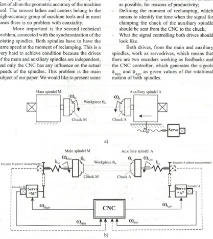
results o f an investigation perform ed in CBKO P ru szk o w , P o la n d , w h ere such an idea o f reclamping was applied to the Venus 350 CNC lathe [1]. The mechanical and kinematic scheme for the synchronization system is shown in Fig. lb).
What is important from the point o f view of the synchronization o f the two spindles?
- The rotational speeds coM and coA have to be the same at the moment o f reclamping;
- The time o f synchronization should be as short as possible, for reasons o f productivity; - D efining the m om ent o f reclam ping, which
means to identify the time when the signal for clam ping the chuck o f the auxiliary spindle should be sent from the CNC to the chuck; - What the signal controlling both drives should
look like.
Both drives, from the main and auxiliary spindles, work as servodrives, which means that there are two encoders working as feedbacks and the CNC controller, which generates the signals d>., and 6. . as given values o f the rotational motion o f both spindles.
Main Spindel M Auxiliary spindel A
a)
Main spindel M Auxiliary spindel A
b)
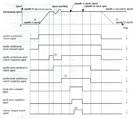
Fig. 2. Scheme o f time performance o f the control signals
The quality o f the synchronization process depends first o f all on the time perform ance o f the <)>Mgiv (t) and <t>Agiv(t) signals, on the stiffness properties kM and kA o f the mechanical parts o f the kinematic chains o f both spindles and on the inertial moments 0 M and 0 A o f the chucks and the workpiece. This m eans that a special schedule o f time performance for all the signals has to be implemented in the CNC controller o f the m achine tools. Fig. 2 shows an exam ple o f such a schedule that we have used in our investigation.
2 EXAMPLES OF EXPERIMENTAL TESTS
We m ade se v e ra l e x p e rim e n ts u sin g a control algorithm like that in Fig. 2. During the in v estig atio n we m easured param eters like the m om ents, M, o f both servodrives, the rotational
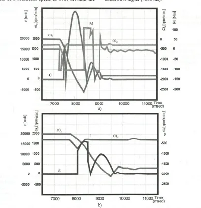
speed, co, o f both drives, and the synchronization error, e, defined as the difference betw een the rotational speed o f the m ain and auxiliary spindles. A n ex a m p le o f th e tim e p e rfo rm a n c e o f the m e a su re d p a ra m e te rs d u rin g th e p ro c e s s o f reclam ping is show n in Fig. 3 and Fig. 4 (the rotational speeds o f both servodrives are shown in re v /m in , th e m o m e n t, M , in N m , b u t th e synchronization error, £ , is in specific units).
example o f the time performance o f the rotational speed o f the main spindle, ooM, the auxiliary spindle, ®A, and the synchronization error, e, for the same rotational speed o f 1700 rev/min, but a longer time constant o f the servodrives, 60 ms. Comparing the two it is clear that from the point o f view o f the synchronization error, e, the time constant o f 60 ms for the servodrives seems to be better than the time constant o f 30 ms. For the time constant o f 30 m s w e can ty p ic a lly o b se rv e sy m p to m s o f overshoots, like the oscillation o f the rotational speed o f the auxiliary spindle (for the stationary state o f a rotational speed o f 1700 rev/m in the
rotational speed o f that spindle reached, in a transient state, up to 2500 rev/min, which means 50% of the stationary state), the synchronization error reached up to 32,000 units and the moment o f the auxiliary drive varied by ±100% o f the maximum value. For the time constant o f 60 ms we observed oscillations too, but these were much smaller. For example, the overshoot o f the rotational speed o f the auxiliary spindle did not exceed 25% o f the rotational speed in the stationary state. The time o f the transient state is about 3000 ms, in contrast to the 30 ms time constant, where the time o f the transient state was about 50% higher (4500 ms).
20000 2000
15000 1500
10000 1000
5000 500 0 0
-5000 -500
Ö,,
5
c S1
j |
2cf
1000 50
-500 0 -1000 -50 -1500 -100 -2000 -150 -2500 -200
Fig. 4. Time performance o f the rotational speed o f the main spindle, (£>Kf, the auxiliary spindle, (Oy, the moment o f the main servodrive, M, the synchronization error, e, fo r a rotational speed o f 1700 rev/min:
A s a g en eral c o n c lu sio n from our in v e stig a tio n we can say th a t the p ro b lem o f synchronizing both spindles during reclamping is a com plex and tim e-consum ing process, and the precision and repeatability o f the reclamping and the loading o f the motors depends on many factors, like: - the rotational speed o f the spindles
- the time constants o f both servodrives, - the quality o f the encoders in both drives, - the quality o f the mechanical parts in both the
“C and “A” axes.
3 SUMMARY
Our investigation o f the synchronization o f both spindles while reclamping allows us to make the following conclusions:
- If the rotational speed o f the synchronization while clamping is too high the loading on the drives increases a great deal and the time for the process increases (comparing the loading o f the drive and the synchronization error while reclamping and after finishing the process, we can say that they differ by a factor o f over 100). - Because the CNC controller has a restriction on
the maximum value o f the synchronization error, the process o f reclamping may fail if the real value o f the synchronization error exceeds the limitation value and the machine tool is stopped. - By finding the appropriate values for the time
co n sta n ts o f the serv o d riv e s an d su ita b le encoders we were able to increase the rotational speed o f reclamping or to decrease the time o f the synchronization.
5 REFERENCES
[1] Report o f CNC Venus lathe investigation. M achine Tool Research and Design Centre (CBKO) Pruszkow (2005) Poland (not published), (in Polish).
[2] Kosmol J. (1998) Servodrives o f numerically controlled machine tools. Science-Technical Publishing House, Warsaw (in Polish).
Authors’ Addresses:Jan Kosmol K rzysztof Lehrich Department o f Machine Technology
Silesian University o f Technology
Gliwice, Poland
Robert Jastrzqbski
Machine Tool Research and Design Centre
Pruszków, Poland
Prejeto:
Received: 14.11.2006
Sprejeto:
Accepted: 28.9.2007