controlled by high temperature mechanism above 1000 k which results in further oxidation of CO. The major advantage of homogeneous charge compression ignition engines is its potential for higher thermal efficiency together with its capabilities to reduce soot and NOx [10]. Despite all these benefits there are some operational issues due to the lack of accurate controllability of ignition and combustion at certain load and speed. Also HC and CO concentration could increase in exhaust gases due to relatively cold in-cylinder regions especially in the crevices and thermal boundary layer [10–17].
Different models have been developed from multi-dimensional [18], multi-zone [20] and single-zone models in an effort to improve our understanding of HCCI combustion and a better description of its features. Fiveland and Assanis [19] constructed a two-zone HCCI model by dividing the combustion chamber into an adiabatic core and a thermal boundary layer zone. In this model mixing of zones is permitted and the thermal boundary layer thickness was calculated for a complete cycle using a simple heat transfer model. Easley et al. [20] used a six zone model to describe the physical processes during combustion; having three adiabatic core zones without any mass transfer and the outer core zone which is permeable to mass with the boundary layer zone and a fixed crevice zone. In this model thermal boundary layer thickness is assumed to be constant since there is not any considerable heat or mass transfer between zones. The combustion process is modeled using chemical kinetics for a set of chemical reactions and the combustion chamber’s temperature and mass distribution is estimated at IVC for initialization of combustion process. It is highlighted that the crevice regions and the boundary layer have an impact on unburned HC and CO emissions. Similar nine zones model was used by Ogink and Golovitchev [21] with estimated temperature–volume fraction distribution at IVC and a fixed thermal boundary layer thickness during compression and expansion strokes. For simplicity heat and mass transfer between all zones has been excluded from calculation which this of course could affect the accuracy of combustion mechanism and also distribution of CO and unburned HC emissions. Xu et al. [22] also used similar scheme introduced by Easley et al., again by neglecting heat and mass transfer between zones which leads to underestimated CO and overestimated HC emissions.
In order to understand better the auto-ignition process in an HCCI engine, the influence of some important parameters on the auto-ignition is investigated by H.Machrafi et al. [23]. The inlet temperature, the equivalence ratio and the compression ratio were varied and their influence on the pressure, the heat release and the ignition delays were measured. The chemical behavior of three different fuel surrogates, containing n-heptane, iso-Octane, toluene, and 1-pentene, under HCCI conditions is analyzed by M. Mehl et al. [24]. New experimental measurements of the in-cylinder composition have been carried out on a running HCCI engine equipped with a special customized cylinder head allowing the direct sampling of the gas.
H.Machrafi et al. in 2008 investigated the possibility of using gasoline in an HCCI engine and analyzed the auto-ignition of gasoline in such an engine. For comparison, a PRF95 and a surrogate containing 11 vol% n-heptane, 59 vol% iso-Octane, and 30 vol% toluene were used. A previously validated kinetic surrogate mechanism was used to analyze the experiments and to yield possible explanations to kinetic phenomena. Their results showed that it is quite possible to use the high Octane-rated gasoline for auto-ignition purposes, even under lean inlet conditions [25].
Because of dominant role of chemical kinetics in HCCI combustion, it is important to have a good understanding of reaction mechanisms of hydrocarbon fuels in order to correctly interpret experimental data and putting HCCI engine development in a right pass. A comprehensive HCCI combustion model should consider fluid mechanics, heat transfer interaction and detailed kinetics aspect of the process [26]. The computational fluid dynamics (CFD) could study the HCCI combustion of simple fuels, but it is often computationally too time consuming to analyze the case of practical fuels. Single-zone HCCI combustion models, on the other hand, permit detailed modeling of the chemical kinetics for practical fuels by assuming that the gas in the combustion chamber is homogeneous also the temperature, pressure and gas composition are uniform. This model can adequately predict ignition in HCCI engine when initial conditions are known. This model could be the best approach when time is important or there is computational limitation.
In this study a thermodynamic single-zone model
with detailed chemical kinetic is used to investigate the effect of hydrogen on HCCI combustion of natural gas. This model assumes that fuel/air mixture homogenously propagates in combustion chamber and considers combustion chamber a single-zone in which pressure, temperature and fuel composition is uniform. Only the closed cycle part of the engine (namely the period between the time of closing intake valve and opening exhaust valve) is modeled. The present work is modeled by means of a detailed chemical kinetic reaction mechanism proposed by Dagaut. [27], which was validated previously by experimental data and includes 97 species involved in 732 reversible reactions. In the present study, specific heat capacity, entropy and enthalpy of species have been calculated from 7-order polynomials that extracted from NASA table [28]. The conservation of mass, energy, and gas-phase species equations are solved and pressure, temperature distributions, mole fraction of species, Co, Co2 and unburned hydrocarbons emissions in each time step are calculated. Also specific fuel consumption and start of combustion are obtained for each case. In this work, the simulation is done for a four valves per cylinder engine and initial conditions are bore of 81.6 mm, stroke of 88.2 mm, compression ratio of 15.0, pressure at IVC of 105 Pascal, and revolutions per minute (RPM) of 1500. Heat transfer from wall is calculated using Woschni [28] heat transfer equation. Wall temperature is considered 1500C.
2. GOVERNING EQUATIONS
2. 1. Conservation of Mass and Energy
Combustion chamber is considered as a closed system with no mass crossing the boundary, therefore total mass of the mixture is constant and dm/dt = 0. Here mkis the kth specie's mass and K the
total number of species. Considering that Yk= mk/m is
the mass fraction of the kth species, the general conservation of mass and in the form of production and destruction of individual species are as follows; respectively:
Where is the specific volume, which may vary with time t and is the molar production
rate of the kth species due to elementary reaction also Wkis the molecular weight of the kth species.
The net chemical production rate of each species is the balance of its production and consumption within chemical reactions involving that species. Each reaction takes place according to forward and backward coefficient rates defined by k, which is obtained from modified Arrhenius equation;
Where Aiis the pre-exponential constant, is the temperature exponent and Eiis the activation energy for reaction i, and these parameters are included in chemical mechanism.
The energy equation for inner zones is;
While for boundary layer and crevice zones with wall heat transfer, becomes;
Where is the specific heat
capacity of gas mixture at constant-volume; P, T, and V are zone pressure, temperature and volume respectively, uk is the internal energy of the kthspecies and hwand Aware zone wall heat transfer coefficient and surface area; respectively. The pressure is derived through ideal gas equation of state:
Where R is the universal gas constant, is the mixture mean molecular weight and is the mass density.
2. 2. Wall Heat-Transfer
Convective heat loss during compression and expansion strokes to the walls at each time step is derived by;
Qwall= hA(T – Twall)
Where h is heat transfer coefficient and is obtained from the following generalized heat transfer
ߩ ܹഥ ൌ ߩܴܹܶഥ ܥ௩ ൌ σୀଵ݉ܥ௩ǡ ߩܥ௩݀ܶ݀ݐ ܸܸܲ݀݀ݐ ݑ ୀଵ ߱ሶܹ݄௪ሺܶ െ ܸܶ ௪ሻܣ௪ൌ Ͳ ߩܥ௩݀ܶ݀ݐ ܸܸܲ݀݀ݐ ݑ ୀଵ ߱ሶܹ ൌ Ͳ ߚ ݇ ൌ ܣܶఉ݁ݔ ൬െܧܴ ܶ൰ ߱ሶ ߱ሶ
ߥ ൌ ܸȀ݉
ௗೖ ௗ௧െ ߥ߱ሶ
ܹ
ൌ Ͳ
,
ௗೖ ௗ௧ൌ ߥ߱ሶ
ܹ
݉ ൌ σୀଵ݉formulation based on user-specified constants of a, b and c which could be obtained from experimental data. For Woschni correlation (2003) which is widely used in internal combustion engine simulation a, b and c are 0.035, 0.8 and 0; respectively.
Nuh= aRebPrc
3. RESULT AND DISCUSSION
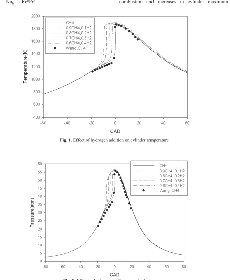
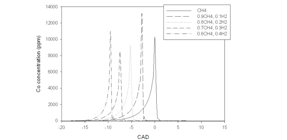
The simulated in cylinder temperature and pressure versus crank angle are shown in figures 1 and 2. As it is shown, hydrogen addition to natural gas, advanced combustion and increases in cylinder maximum
Fig. 1.Effect of hydrogen addition on cylinder temperature
Fig. 2.Effect of hydrogen addition on cylinder pressure
temperature, but its effect on maximum pressure is negligible. This is due to hydrogen low motor octane number (MON), which causes its less resistance to auto-ignition rather than natural gas. The results are compared with the results of Z. Wang et al[29]. for natural gas combustion which shows good agreement. The effect of hydrogen addition to natural gas on calculated start of combustion is shown in Fig 3. By addition 10 percent hydrogen to natural gas, start of
combustion advances approximately 3 crank angle degree (CAD), and by increasing share of hydrogen to 40 percent, start of combustion advances around 10 CAD, which shows remarkable effect of hydrogen addition on advancing start of combustion which is due to its low motor octane number.
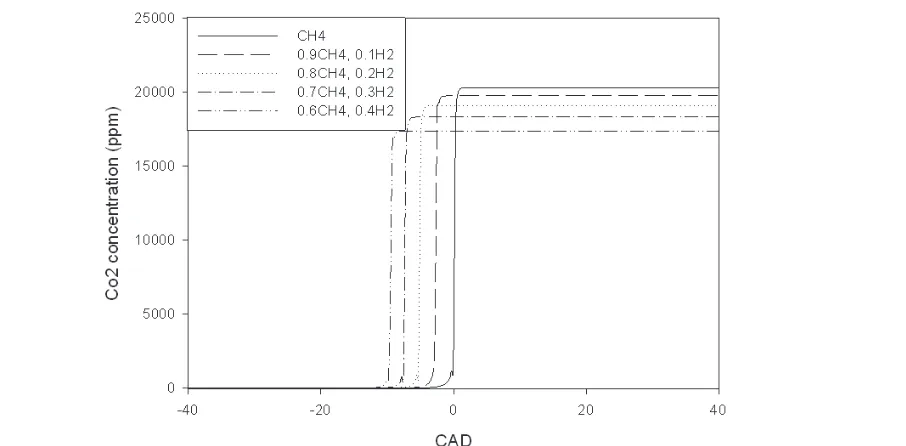
The result for calculated Co, Co2 and unburned
hydrocarbons are shown in figures 4 to 7. As it is shown in Fig 4, hydrogen addition does not have any Fig. 3.Effect of hydrogen addition on start of combustion
Fig. 4. The effect of hydrogen addition on CO concentration
specific effect on maximum concentration of Co, but by increasing the amount of hydrogen the spread of Co production becomes narrower and its production starts sooner. As it is shown in figures 5, 6 and 7, exhaust Co, Co2 and unburned hydrocarbons decreases by
increasing hydrogen portion in intake mixture. This is because of fixed intake pressure and temperature in all cases which means that the volume of intake mixture
is the same in all cases, and as a result, by increasing hydrogen portion in intake mixture the mass of natural gas and therefore carbon molecules in the intake mixture decreases which lead to decrease in carbon included emissions. It is also obvious from Figs 6 and 7 that, increasing in hydrogen portion in intake manifold, advances the start of Co2 production and unburned hydrocarbons.
Fig. 5. The effect of hydrogen addition on exhaust CO
Fig. 6. The effect of hydrogen addition on CO2 concentration
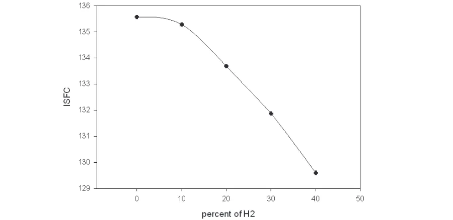
The effect of hydrogen addition on specific fuel consumption is shown in Fig. 8. As it is shown, the increase in hydrogen amount decreases the ISFC. This could be due to two folds; hydrogen has a smaller molecular weight comparing to natural gas and performs a more complete combustion which ends up with higher heat release.
Brief analysis of the chemical kinetics will provide a better understanding of the combustion process. The important reactions in CH4-H2 combustion are listed below [27]:
H2+ OH = H2O + H (1) H + O2+M = HO2+M (2)
CH4+ H = CH3+ H2 (3)
HO2+ HO2= H2O2+ O2 (4)
CH3+ HO2= CH3O + OH (5) H + HO2= OH + OH (6) H2O2 = OH + OH (7)
OH + CH4= CH3+ H2O (8)
Net reaction rates of these important reactions for combustion of CH4with 20% of H2are shown in Fig. Fig. 7. Unburned Hydrocarbons concentration(ppm) versus crank angle
Fig. 8. Effect of hydrogen addition on indicated specific fuel consumption
9. As is shown, reaction 8 is the most effective reaction for consumption of CH4, which means OH is
the most crucial species for increasing or decreasing combustion rate of CH4. As is shown in reaction 1 through 8, H2addition leads to an increase in radical H according to reaction (1). H contributes to the production of HO2and CH3 via reactions (2) and (3)
respectively. HO2 partially converts to H2O2 via reaction (4). CH3, HO2and H2O2 are crucial radicals and they promote the formation of OH via reactions
(5), (6), and (7). OH plays a crucial role in the oxidation of CH4 via reaction (8). Thus H2 addition
leads to more OH radicals, the ignition is advanced, and the temperature and the pressure are enhanced. The mole fraction of OH for different studied cases is shown in Fig. 10. As is shown, by increasing H2 the OH production advances and its mean value increases which leads to advance in start of combustion. The maximum amount of OH mole fraction is not reliable, because it occurs in a short window of time which may Fig. 9. Net reaction rate of important reactions
Fig.10. Effect of addition of H2to CH4on radical OH
be due to rapid increase in pressure in single zone modeling.
4. CONCLUSION
A thermodynamic single-zone model with a detail chemical kinetic mechanism is used to model the combustion of five different blended natural gas and hydrogen fuels in an HCCI engine. The chemical kinetic mechanism that has been used in this work includes 732 reactions. The results of the simulations can be summarized as the following:
• Hydrogen addition to natural gas improves HCCI combustion characteristics namely; less emissions and better performance.
• Since hydrogen is a lighter fuel rather than natural gas, its addition to natural gas increases peak pressure and temperature, it also advances start of combustion.
• Increasing hydrogen portion in intake mixture from 0 to 40 percentages, advances start of combustion around 10 crank angle degrees. • Hydrogen addition to natural gas decreases
carbon included emissions.
• Hydrogen decreases ISFC, which means it releases much energy than natural gas with the same weight.
• Blending two fuels with different characteristics can improve HCCI combustion performance and emissions.
ACKNOWLEDGMENT
The support of Computer Aided Engineering Center of Iran University of Science and Technology is acknowledge and highly appreciates
REFERENCES:
[1] Onishi, S., SH. Jo, K. Shoda, PD. Jo and S. Kato, 1979. Active thermo-atmosphere combustion (ATAC) – a new combustion process for internal combustion engines. SAE paper 790501.
[2] P.M. Najt, D.E. Foster, SAE Paper 830264, 1983.
[3] T. Aoyama, Y. Hattori, J. Mzuta, Y. Sato, SAE Paper 960081, 1996.
[4] M. Richter, A. Franke, M. Alden, A. Hultqvist,
B. Johansson, SAE Paper 1999-01- 3649, 1999. [5] A. Hultqvist, M. Christensen, B. Johansson, A. Franke, M. Richter, M. Alden, SAE Paper 999-01-3680, 1999.
[6] A. Hultqvist, M. Christensen, B. Johansson, M. Richter, J. Nygren, J. Hult, M.Alden, SAE Paper 2002-01-0424, 2002.
[7] Furutani, M., Y. Ohta and K. Komatsu, 1993. Onset behavior of low-temperature flames caused by piston compression. JSAE Rev, 14(2): 8–12.
[8] Pucher, G.R., DP. Gardiner, MF. Bardon and V. Battista, 1996. Alternative combustion systems for piston engines involving homogeneous charge compression ignition concepts – a review of studies using methanol, gasoline and diesel fuel. SAE paper 962063.
[9] Najt, P.M. and D.E. Foster, 1983. Compression ignited homogeneous charge combustion. SAE paper 830264.
[10] Alkidas AC. Combustion advancements in gasoline engines. Energy Convers Manage 2007;48:2751–61.
[11] Soylu S. Examination of combustion characteristics and phasing strategies of a natural gas HCCI engine. Energy Convers Manage 2005;46:101–19.
[12] Peucheret S, Wyszynski ML, Lehre RS, Golunski S, Xu H. Use of catalytic reforming to aid natural gas HCCI combustion in engines: experimental and modeling results of open-loop fuel reforming. Hydrogen Energy 2005;30:1583–94.
[13] Bhave A, Kraft M, Montorosi L, Mauss F. Sources of CO emissions in an HCCI engine: a numerical analysis. Combust Flame 2005;144:634–7.
[14] Christensen M, Johansson B, Einewall P. Homogeneous charge compression ignition (HCCI) using isooctane, ethanol and natural gas – a comparison with spark ignition operation. SAE paper no. 972874; 1997.
[15] Christensen M, Johansson B, Amneus P, Mauss F. Supercharged homogeneous charge compression ignition. SAE paper no. 980787; 1998.
[16] Hultqvist A, Christensen M, Johansson B, Franke A, Richter M, Alden M. A study of the homogeneous charge compression ignition
combustion process by chemiluminescence imaging. SAE paper no. 1999-01-3680; 1999. [17] Hultqvist A, Endgar U, Johansson B,
Klingmann J. Reacting boundary layers in a homogeneous charge compression ignition (HCCI) engine. SAE paper no. 2001- 01-1032; 2001.
[18] Jia M, Xie M. Numerical simulation of homogeneous charge compression ignition combustion using a multi-dimensional model.
Proc IMechE J Automobile Eng
2007;221:465–80.
[19] Fiveland SB, Assanis DN. Development of a two-zone HCCI combustion model accounting for boundary layer effects. SAE paper no. 2001-01-1028; 2001.
[20] Easley WL, Agarwal A, Lavoie GA. Modeling of HCCI combustion and emissions using detailed chemistry. SAE paper no. 2001-01-1029; 2001.
[21] Ogink R, Golovitchev V. Gasoline HCCI modeling: an engine cycle simulation code with a multi-zone combustion model. SAE paper no. 2002-01-1745; 2002.
[22] Xu H, Liu M, Gharahbaghi S, Richardson S, Wyszynski M, Megaritis T. Modelling of HCCI engines: comparison of single-zone, multi-zone and test data. SAE paper no. 2005-01-2123; 2005.
[23] Machrafi, H. and S. Cavadiasa, 2009. An experimental and numerical analysis of the influence of the inlet temperature, equivalence ratio and compression ratio on the HCCI auto-ignition process of Primary Reference Fuels in an engine. Fuel processing technology paper. [24] Mehl, M., T. Faravelli, E. Ranzi, D. Miller and
N. Cernansky, 2009. Experimental and kinetic modeling study of the effect of fuel composition in HCCI engines. In the proceedings of the 2009 Combustion Institute. 32: 2843-2850.
[25] Machrafi, H. and S. Cavadias, 2008. Three-stage autoignition of gasoline in an HCCI engine: An experimental and chemical kinetic modeling investigation, Combustion and Flame. 155:557–570.
[26] Mingfa, Y., Z. Zhaolei and L. Haifeng, 2009. Progress and recent trends in homogeneous charge compression ignition (HCCI) engines. Progress in Energy and Combustion Science.
35:398-437.
[27] Philippe Dagaut, Guillaume Dayma, Hydrogen-enriched natural gas blend oxidation under high-pressure conditions: Experimental and detailed chemical kinetic modeling, International Journal of Hydrogen Energy 31 (2006) 505 – 515
[28] Heywood, J.B., 1988. Internal Combustion Engines Fundamentals. McGraw-Hill Press. [29] Zi-han Wang; Chun-mei Wang; Hua-xin Tang;
Cheng-ji Zuo; Hong-ming Xu, Effect of Hydrogen Addition on ethane HCCI Engine Ignition Timing and Emissions Using a
Multi-zone Model, CHINESE JOURNAL OF
CHEMICAL PHYSICS VOLUME 22,
NUMBER 3 (2009)