OPTIMIZATION OF PROCESS PARAMETERS FOR THE
PRODUCTION OF LH CHANNEL USING CNC MILLING
* Dr. Ramachandra C G, Rohini M ** Rishi J P,
*** Dr. Srinivas T R, **** Virupaxappa B
* Department of Mechanical Engineering Srinivas Institute of Technology, Mangaluru, India
** Department of Mechanical Engineering Vidyavardhak College of Engineerng, Mysuru, India *** Department of Industrial and Production Engineering Sri Jayachamarajendra College of Engineering , Mysuru, India
**** Department of Mechanical Engineering
Dr M.V. Shetty Institute of Technology, Moodbidri, India.
ABSTRACT
Today’s market imposes stringent demands regarding the product quality/price ratio. Furthermore, products are increasingly manufactured in small batches and high varieties, which require flexibility not only from manufacturing system but the entire manufacturing process. Such demands require manufacturing systems which are highly automated in the domain of preparation and realization of manufacturing activities, which include fixture design. Fixtures are the special production tools which make the standard machine tool, more versatile to work as specialized machine tools. This paper deals with design, manufacturing, Cost Estimation and analysis of fixture for a component named “LH Channel” which is machined in CNC Milling. For better visualization and understanding 3D modelling of the fixture is done by using Solid Works software and analysis is done by using ANSYS software. The proposed fixture is designed to adopt cost effective manufacturing process so that it can be machined easily with a lesser time and in turn it saves the machining time and manufacturing cost.
Keywords: Optimization; Process Parameters; LH Channel; Production; CNC Milling:
INTRODUCTION
2 work piece to ensure that each work piece is machined within the specified limits. Set blocks and feeler or thickness gauges are used with fixture to reference the cutter to the work piece. A fixture should be securely fastened to the table of the machine upon which the work is done. Though largely used on milling machines, fixtures are also designed to hold work for various operations on most of the standard machine tools.
Some of the researchers worked in this area are, N.Kaya and F.Ozturk [02] have noticed that the workpiece stability and deformation analysis under dynamic machining conditions are taken into account for time varying machining loads. Chip removal effect is also taken into account. Djordje Vukelic and Janko Hodolic [03] have specified that new technologies have the main aim to reduce time and costs in new fixture construction design and find optimal solution for specific manufacturing conditions. Input information's for design can be divided into two general groups. Manufacturing characteristics (machining type, type of machine tool, number of tools, number of machined surfaces, fixture attachment to machine tool, etc). Work piece characteristic(shape of work piece, size of the work piece, number of degrees of freedom to a work piece locating principle, shape of locating surfaces, clamping schemes, type of clamp, clamping forces, direction of clamping etc). Jo Lee and L.S. Haynes [04] have specified that the work is done on the work piece; high stress may cause failure of the work piece; and large deformation may cause the loss of accuracy in precision machining so rigid clamping is necessary. Y.G.Liao and S.J.Hu [05] have mentioned that the Surface quality is a major factor affecting the performance of a component. The machined surface quality is strongly influenced by the external loads during the fixturing and machining processes. Haiyan Deng and Shreyes N. Melkote [06] have described that the systematic approach for analyzing the dynamic stability of a fixtured workpiece during machining.
CNC MILLING
CNC Milling is the most common form of CNC. These machines [07] are special computerized equipment used for flat, solid or even rough surfaces. These machines are used to bore, cut gears, produces slots and drill. There are different types of milling machines but they are usually classified in two: the vertical and horizontal spindle machine. The horizontal spindle machine is very strong and powerful kind of machine. Multiple varieties of cutter are attached to the equipment to side, form, and face, to shape and remove materials. Normally, the milling operation creates plane surfaces. Other geometries can also be created by milling machine. Milling operation is considered an interrupted cutting operation teeth of milling cutter enter and exit the work during each revolution. This interrupted cutting action subjects the teeth to a cycle of impact force and thermal shock on every rotation. The tool material and cutter geometry must be designed to bear the above stated conditions. Depending upon the positioning of the tool and workpiece the milling operation can be classified into different types. CNC Milling is the most common form of CNC. These machines are special computerized equipment used for flat, solid or even rough surfaces.
the table. A six-axis CNC milling machine would have another horizontal pivot for the milling head, this time perpendicular to the fifth axis. The base and frame are the major parts of the milling machine. This two are consist of different components. The reservoir is can be found in the base that is used to cut fluid. The knee is connected to the column and accommodates the feeding mechanisms. The columns function is to guide and supports the knee when it is vertically moved. The saddle is attached to the knee and can be cross travel. The table's function is to support the workpiece. The traverse handwheel and crossfeed of the table is used to travel the table. The spindles function is drive and hold the attachments of the machine. The arbor holds the milling machine cutters
SPECIFICATIONS OF A MILLING MACHINE
A. Milling Spindle Drive Speed range: 40-4000 rpm Drive power: 3.3 or 4 KW
Spindle nose taper: ISO 40/M16 with drawing groove
B. Feed Drives
Feed rate at all axes : 2-3000 rpm
Rapid traverse in X and Y axes: 6000 mm/min Rapid traverse in Z axes: 5000 mm/min
C. C-axes
Speed range: 0-90º/min Turn table torque: 520Nm
Turn diameter torque NCT 500: 500mm 2 alignment slots: 14 H7
14 alignment slots: 14 H12
D. Cutting Force Calculation for Milling 1. Velocity of the Cutting Tool (Vc)
Vc=πDn/1000
Where,
Vc= Velocity of cutting tool (m/sec)
D= Diameter of the cutter = 12mm n = Speed (rpm) = 3000 rpm Vc= 113.097 m/sec
2.Feed : 1000 3. Depth of cut : 10.5 4. Cutting force
F=6120N/Vc
Where,
4 Vc = 113.097 m/sec
F=6120x1.08/113.097 F=58.44kgf
F=58.44 x9.81= 573.29 N F=573.29 N
Therefore from the above calculations, we can conclude that, Velocity of the cutting tool(Vc)= 113.097 m/sec
Cutting Force (F) = 573.29 N
The machining forces on to the component is calculated under machining condition by considering the various parameters (cutting speed, feed, depth of cut etc) from these cutting forces the analysis is done for the fixturing element.
COMPONENT DETAILS
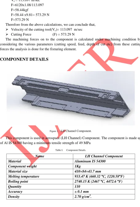
Figure 1. LH Channel Component.
This component is used in aerospace (LH Channel) Component. The component is made up of Al IS 54300 having a minimum tensile strength of 49 MPa
Table I. Component Details.
Name LH Channel Component Material Aluminum IS 54300
Component weight 1Kg
Material size 410×84×43.7 mm
Melting temperature 933.47 K (660.32 °C, 1220.58°F) Boiling point 2740.15 K (2467 °C, 4472.6 °F)
Quantity 110
A.
Component Material (Aluminum IS 54300)
Aluminum is found primarily in bauxite ore. Pure aluminum is soft, silvery, ductile of the poor metal group of chemical elements, which is corrosion resistant, light weight and high electrical conductivity. It has the symbol Al and atomic number 13. The metal is used in many industries to manufacture a large variety of products and is very important to the world economy. Structural components made from aluminum and its alloys are vital to the aerospace industry and very important in other areas of transportation and building. It is widely used for foil and conductor cables, but alloying with other elements is necessary to provide the higher strengths needed for other applications.
B.
Material Properties
Aluminum is a soft, lightweight metal with normally a dull silvery appearance caused by a thin layer of oxidation that forms quickly when the metal is exposed to air.
Aluminum oxide has a higher melting point than pure aluminum. Aluminum is nontoxic (as the metal), nonmagnetic, and nonsparking.
It has a tensile strength of about 49 MPa in a pure state and 400 MPa as an alloy.
Aluminum is about one-third as dense as steel or copper; it is malleable, ductile, and easily machinable and castable.
It has excellent corrosion resistance and durability because of the protective oxide layer.
Aluminum mirror finish has the highest reflectance of any metal in the 200-400 nm (UV) and the 3000-10000nm (far IR) regions, while in the 400-700 nm visible range it is slightly outdone by silver and in the 700-3000 (near IR) by silver, gold, and copper.
It is the second-most malleable metal (after gold) and the sixth-most ductile. Aluminum is a good thermal and electrical conductorC.
Advantages of Aluminum when Compared with Steel
Aluminum is three times lighter than steel and yet can offer high strength when alloyed with the right elements.
Aluminum can conduct electricity six times better than steel and nearly 30 times better than stainless steel.
Aluminum provides excellent corrosion resistance. Aluminum is easy to cut and form.
Aluminum is nontoxic for food applications.
Aluminum is non-magnetic therefore arc blow is not a problem during welding. Aluminum has a thermal conductivity rate five times higher than steel. The high
thermal conductivity creates a great heat sink which can create insufficient weld fusion on parts over 4 mm and weld burn through issues on parts less than 3 mm. Aluminum provides welds that are less viscous which is a problem when trying to
6
Aluminum has a low melting point 1,200 degrees F, this is more than half that of steel. For a given MIG wire diameter the transition short to spray weld current for aluminum is much lower than it is for steel.
D.
Raw Material Selection
Material selection is a matter of quality and cost. The properties of the material must be adequate to meet design requirements and service conditions. While manufacturing any machinery parts, moulds, press tools, equipment, gauges, jigs and fixtures etc, raw material selection plays vital role. Selection of raw material depends upon the function of manufacturing parts.
MANUFACTURING OF THE COMPONENT
A.
Manufacturing by using Vice
Vice is a device that analyses all the available information regarding the material and geometry of the workpiece, operations required, processing equipment for the operations and the operator. Following are the steps to be considered in manufacturing of component with Vice.
1. The raw material given by the customer has irregular surface and it is premachined. The length and width of the material according to the drawing are to be planed keeping extra 5mm. Premachining is done using conventional machine to reduce the machining cost. It can also be done in CNC machine, but it is not cost effective so we use the conventional machine.
2. Second step is, it is done in vertical milling machine. The component is located on the vice. First thickness of the job is done, length and width is done as per drawing size, and 6 holes of Ø2.5mm are drilled.
3. Third step is, it is done in horizontal milling machine. In this machine, the component is having machining activities on 4 faces. The component is located on vice or angle plate. The individual datum(x, y) are taken for the first face of component. The relevant operations are carried out. The component is removed from vice and bench work (demurring) is carried out.
4. Fourth step is, vice is rotated to 90º, and then individual datum(x, y) are taken for the second face of component. The relevant operations are carried out. The component is removed from vice and bench work (demurring) is carried out.
5. Fifth step is, vice is rotated to 180º, and then individual datum(x, y) are taken for the third face of component. The relevant operations are carried out. The component is removed from vice and bench work (demurring) is carried out.
6. Sixth step is, vice is rotated to 270º, and then individual datum(x, y) are taken for the fourth face of component. The relevant operations are carried out. The component is removed from vice and bench work (demurring) is carried out.
.
B.
Manufacturing by using Fixture
Fixture is designed using the software SolidWorks. The material for fixture is Mild Steel ST42. Here, component passes through 4 faces. The component is having machining activities on 4-axis horizontal milling machine. The machine used for this operation is MIKRON UMC600 having controller Hiedenhain. So 4-axis Horizontal milling machine is used to hold and locate the fixture plate and it is located on rotary table. Fixture plate contains two units:
Top plate Base plate
Top plate is assembled with base plate, surface grinding is done for top plate. If the surface grinding is done for top plate without assembling with the base plate, then there will be no parallelity between top plate and machine bed. It is case hardened to avoid scratches and damages during consequent location of component. Pin hole is used to locate the position of the component. M8 Tap hole is used to clamp the top plate to the base plate.
1. The raw material given by the customer is premachined. Previously the material is in irregular surface. The length and width of the material is maintained according to the drawing size, keeping 5mm extra dimension. Premachined is done using conventional machine to reduce the machining cost. It can also be done in CNC machine, but it is cost effective so we use the conventional machine.
2. Pin and tap holes are made. Material is loaded on the vice then the following operations are done. 2pin holes of Ø10mm H7 are drilled to locate the component for III setting.2 tap holes are drilled to hold the component for III setting.
3. It is done in vertical milling machine. Here we can also use fixture plate. Component is held on the fixture plate using M8 bolt and located in Ø10mm Dowell pin. First thickness of the job is done, length and width is done as per drawing size, and 6 holes of Ø2.5mm are drilled.
4. 4-axis Horizontal milling machine is used to hold and locate the fixture plate and it is located on rotary table. Component passes through 4 faces which is located on Fixture plate. The rotary table is rotated after the completion of each face as per the degrees mentioned i.e., 0º, 90º, 180º, 270º
8 .
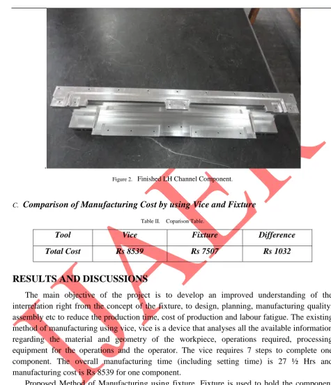
Figure 2. Finished LH Channel Component.
C. Comparison of Manufacturing Cost by using Vice and Fixture
Table II. Coparison Table.
Tool Vice Fixture Difference
Total Cost Rs 8539 Rs 7507 Rs 1032
RESULTS AND DISCUSSIONS
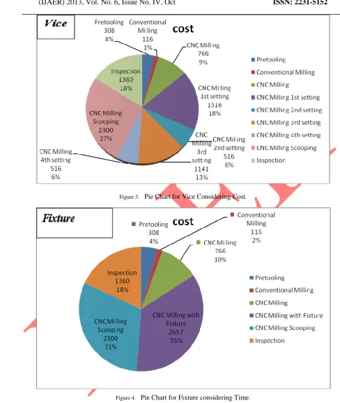
The main objective of the project is to develop an improved understanding of the interrelation right from the concept of the fixture, to design, planning, manufacturing quality, assembly etc to reduce the production time, cost of production and labour fatigue. The existing method of manufacturing using vice, vice is a device that analyses all the available information regarding the material and geometry of the workpiece, operations required, processing equipment for the operations and the operator. The vice requires 7 steps to complete one component. The overall manufacturing time (including setting time) is 27 ½ Hrs and manufacturing cost is Rs 8539 for one component.
Proposed Method of Manufacturing using fixture. Fixture is used to hold the component during manufacturing. There are only 5 steps required for the completion of one component. Here, component passes through 4 faces. The component is having machining activities on 4-axis horizontal milling machine. The machine used for this operation is MIKRON UMC 600 having controller Hiedenhain. So 4-axis Horizontal milling machine is used to hold and locate the fixture plate and it is located on rotary table. The overall manufacturing time (including setting time) is 24 ½ Hrs and manufacturing cost is Rs 7507 for one component.
Figure 3. Pie Chart for Vice Considering Cost.
Figure 4. Pie Chart for Fixture considering Time.
Hence the following result is achieved using fixture.
The total cost required to manufacturing one component is reduced to Rs 1032. Cost of the component is considerably reduced by using Fixture.
The fixture which is designed will reduce the human fatigue, lead time and hence increases the profits and the productivity.
10
This is a batch production. In this we are producing 110 components. So, for total production the difference is Rs 1,13,520 costs.
CONCLUSIONS
Today’s manufacturing aims at achieving high productivity, better quality to reduce unit cost. This necessitates work holding devices to be efficient, i.e., to increase the rate of loading and unloading to speed up the manufacturing cycle time. By optimizing the process parameters such as velocity of cutting tool, feed, depth of cut and cutting force etc., the total cost required to manufacturing one component is reduced to Rs 1032. Cost of the component is considerably reduced by using Fixture. The fixture which is designed will reduce the human fatigue, lead time and hence increase the profits and the productivity. The overall quality of the machining was found to be much better than compared to the Vice. By using this solution, an unskilled labour can also be employed, as his job would be to only load and unload the component in the Horizontal Machining Centre. Therefore, savings in labour costs can be achieved. This is a batch production. In this we are producing 110 components. So, for total production the difference is Rs 1,13,520 costs.
.
REFERENCES
[1] Boothroyd, “Fundamentals of Metal Machining and Machine Tools”, McGraw Hill, 2000. [2] N.Kaya, F.Ozturk, “Contact Analysis of Workpiece – Fixture”, Gorukle, Bursa 16059
Turkey.
[3] Djordje Vukelic, Janko Hodolic, “Machining fixture design via expert system”, 49th
anniversary of technical sciences, Novisad, May 18th 2009.
[4] Jo Lee, L.S. Haynes, “Finite-Element Analysis of Flexible Fixturing System”,
Gaithersburg, Vol. 109, Journal of Engineering for Industry, May 1987.
[5] Y.G. Liao, S. J. Hu, “An Integrated Model of a Fixture - Workpiece System for Surface
Quality Prediction”, Hayward Street, International Journal of Advanced Manufacturing Technology, Ann Arbor USA, 2001.
[6] Haiyan Deng, Shreyes N. Melkote, “Analysis of Fixturing Dynamic Stability in
Machining”, Monterey, California, USA, 24-28 July, 2005.
[7] Alan Overby, “CNC Machining Handbook: Building, Programing and Implementation”,
Kindle Edition, 2010.
[8] Thomas M Crandell, David Gibbs, “CNC Machining and Programming-An Introduction”,