Analysis of Heat Exchanger
Deepak Satsangi Dr. Lavendra S. Bothra
PG Student Professor
ARMIET, Mumbai University, India ARMIET, Mumbai University, India
Abstract
Ever since human civilization has evolved, it has made continued Improvements to the various instruments used by them. This continued improvements and changes have made this modern era possible where humans enjoy their own inventions which includes energy consuming devices like fan, light, AC, etc. Recently we have observed the shortfall of energy generation in comparison to energy demand, especially in developing countries such as India, Pakistan, etc. In such situations, Improvement of energy efficiency in energy generation side as well as energy consumption side. Such efforts have led to development of LED bulbs and CFL bulbs on energy consumption side and many thermal efficiency improvement methods on the energy generation side. Heat Exchanger is a device which has wide applications ranging from Energy Generation like power plants to Energy consumption like AC Plants and used in Chemical Industries on a Large Scale.
Keywords: Heat Exchanger, Energy Efficiency, STHE, Elliptical Tubes, Flow Parameters
_______________________________________________________________________________________________________
I. INTRODUCTION
Geothermal fluids comprise of various substance compositions relying upon their area yet the primary chemicals incorporate hydrogen sulfide (H2S), arsenic (As), boron (B), and mercury (Hg). At the point when released into the atmosphere these chemicals can be harming to the adjacent condition. Numerous areas have stringent directions about the treatment of the geothermal liquid, in this way requiring full injection of the liquid once the sum total of what vitality has been separated. Accepting that full re-injection happens, accessibility of water for cooling and the subsequent noticeable plume is subjects of concern.
The accessible water source assumes a critical part in a water cooled system as the water necessity is persistent for once-through wet cooling systems and for those combined with a cooling tower. Water cooled systems regularly require around 20 liters of cooling water per megawatt hour. Along these lines, in dry districts where water is rare, air cooled systems can be a practical option. Presently air cooled systems are combined with double geothermal power plants and other paired fossil fuel plants. In this manner, a modular wellhead solution company by the name of Green Energy Group AS (GEG) offers the conversation starter of utilizing an air cooled condenser (ACC) with a glimmer steam geothermal system. The company reached an ACC solution seller by the name of GEA Power Cooling Inc. (GEA) for a budgetary citation and a preparatory design.
Their design data is utilized as a part of the present proposition to take into account an applicable solution. Cooling System Summary
When taking a gander at the three sorts of cooling systems previously portrayed, it is between testing to perceive how they compare. Table 1 records the principle components for correlation and if the component is present in the corresponding system it is set apart by "x”.
Table - 1
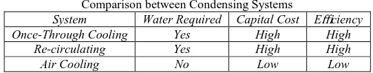
Comparison between Condensing Systems
System Water Required Capital Cost Efficiency Once-Through Cooling Yes High High
Re-circulating Yes High High Air Cooling No Low Low
From the table it is clear that air cooling isn't perfect for power plants on a low spending plan. Because of the high capital cost it is of most extreme significance to design these units for a successful performance. As said before, an air cooled condenser does not rely on any water sources close-by for cooling purposes. Consequently, air cooled systems can demonstrate helpful in those areas where environmental regulations are stringent and water is rare.
II. LITERATURE REVIEW
Among all the recent research on this subject, I feel that the most significant of them is the one done by MIT researchers, who have demonstrated that adding a thin layer of grapheme, can lead to more proper drop-wise condensation (which gives much higher H.T. coefficient, in comparison with film condensation), thus improving heat transfer efficiency in condenser.
replacing the circular tubes with oval tubes and adding strategically located vortex generators (winglets) in the fins. The result conform that addition of winglets increases heat transfer coefficient by approx. 35 % compared to normal tubes.
SudhanshuDogra, Satyam Kumar, GauravChaudhary, Awadhesh Kumar, L Chaitanyastudied the effect of changing the materials on the condensers (2 materials- copper and SS304) An experimental study has been carried out to see the effect of Condenser Material on the effectiveness of Condensers. The result showed that copper as a material gave higher effectiveness, with higher life in saline water, but copper was also more costly than SS304.
J.H Lee, S.W Bae, K.H Bang, M.H Kim performed an experimental study of a fin and tube condenser using two different configurations of condenser paths (U and Z type) and two kinds of refrigerants (R-22 and R-407C) as working fluids. After both experimental and numerical analysis, it wasfound that R-22 performs better than R-407C for the Z-type path configuration, whereas no significant difference was found between results using either refrigerant in the U-type path configuration. On average, the numerical results obtained with R-22 were 10.1% greater than experiment data; using R-407C, results were 10.7% less than experiment data.
MadhuJhariya, P.K.Jhinge and R.C. Gupta presented in a research paper the experimental performance of a window air conditioner with two different types of condensers, single channel and multi-channel condenser. The air-conditioner is a 1 TR unit designed for R-22. The performance of the air-conditioner with R-410A is compared with the baseline performance with R-22.Test results shows that for R-22 the COP of multi-channel condenser is 6.6% efficient than the single channel condenser. The cooling capacity of multi-channel condenser is 38.4 % higher than the single channel condenser.
K. Sivakumar, N. Krishna Mohan, and B. Sivaraman investigated experimentally and theoretically the performance of an elliptical heat pipe solar collector. The results gathered were obtained by conducting research work at Chidambaram in India, andwere according to the solar conditions at Chidambaram.
SérgioNascimentoBordalo and Francisco Eduardo MourãoSaboya experimentally determined the Pressure Drop Coefficients for Elliptic and Circular Sections in One, Two and Three-Row Arrangements of Plate Fin and Tube Heat Exchangers. They made the graphs showing the variation of pressure loss coefficient with Reynolds’ number for both circular and elliptical sections. GEA, (2012) numerous mixes of tube and fin shape are conceivable relying upon the business and application. For instance, GEA Group, a main supplier of ACCs, makes different fin tube package plans incorporating flat steel tubes with brazed aluminum fins, round steel tubes with helical fins, and elliptical steel tubes with aroused rectangular steel fins. Regularly utilized fins plans for air-cooled mechanical heat exchangers incorporate grooved– in or firmly twisted aluminum fins, plate fins, louvered fins, dimpled fins, perforated plate fins, and others.
Kim et al. (2007) utilized a different relapse system on a database of 41 wavy fins, which incorporated the information, to create relationships for stunned and in-linevarieties of circular tubes. The relationship produced for the amazed design could foresee 92 percent of the heat exchange information inside 10 percent and 91 percent of the contact factor information inside 15 percent. Wavy aluminum fins attached to flattened aluminum clad steel tubes can likewise be utilized. This outline, found to have great execution qualities, may supplant at least two columns of curved or round tubes (Nagel, 1994). Connections to foresee heat exchange and weight drop execution of the wavy fins have been created tentatively and additionally through numerical or computational fluid flow reenactments for the greater part of the diverse wavy fin profiles.
KirtanGohel compared the effect of having helical baffle with that of normal flat baffle having 3:2 cutting ratio, in a Shell and Tube Type Heat Exchanger. The results showed that effectiveness of helical baffle is high compared to flat baffle for same inlet temperature of hot water and cold water.
A trial examination of N. D. Shirgire and P. Vishwan gives variety of general heat exchange coefficient for strait tube and helical loop heat exchanger by keeping consistent mass stream rate of high temp water and changing the cool water massstream rate. The diagrams attracted there look into papers demonstrates the expansion in general heat exchange rate with increment in mass stream rate. General heat exchange coefficient is higher for helical coil heat exchanger when contrasted with straight tube heat exchanger. Otto J. Nussbaum contemplated all significant kind of condensers and explore the impacts of points of interest and burdens of different condensers on execution of refrigeration systems. Air cooled condensers with little limit i.e. 5 to 7.5 Hp is normally utilized as indoor consolidating unit. Choice of condensers is relies upon the aggregate heat dismissal (THR) and amount of flowing fluid.
Park and Jacobi, (2009) Louvered surfaces, being used since the 1950s and easy to fabricate, are utilized to interfere with the flow and separate the thermal boundary layer to upgrade heat exchange. Heat exchangers with flat tubes and multi-louver fins are regular in air-cooling applications because of smallness, and the lessened material and required fan power. Flow through the louvered fins can be ordered as "pipe" flow at bring down flow rates because of the thicker boundary layers that create, which limit the flow inside the louver holes. As flow speed expands, boundary layers thin, enabling the flow to take after the louver ways. Run of the mill flat-tube multi-louver heat exchangers have numerous airside and tube-side geometric parameters that can impact execution; in this way vast data banks are important to create precise air-side execution relationships.
III. RESEARCH METHODOLOGY
Research is a systematic endeavor to get answers to significant inquiries about wonders or occasions through the use of logical strategies. It begins with an issue, gathers information or realities, examinations them basically and achieves choices in view of the genuine confirmations. Along these lines it is a watchful and unending quest for truth and an interminable mission for learning.
IV. DATA TAKEN FOR THE STUDY
The data of surrounding parameters such as inlet temperature of working fluid, working fluid pressure, etc. was taken from an already running system in a real life plant, working under steady-state conditions. The construction details of the condenser was taken from the same real life application.
V. RESEARCH DESIGN
Standard design studied by suitably modeling it in a computer aided program and analyzing the data by analysis in a computer program such as ANSYS. After that, a parameter (whose effect we want to study) modified in the geometry of the standard design (such as circular tubes can be replaced by elliptical tubes of suitable size at different angles or fins can be modified) the analysis will be done in the same computer program, and results can be compared in each case with the original results (which were obtained by the standard design).
VI. OBJECTIVES OF THE STUDY
The objective of this dissertation would be to study the impact of replacing circular tubes, with elliptical tubes of similar size. Also we can find the angle at which the elliptical profile will be the most efficient. We can rotate the elliptical profile at different angles in a 2-D plane, and check the effect of variation on the condenser, leading us to finding the most efficient angle of rotation.
VII.RESULT & ANALYSIS
The flow parameters are fluctuated by presenting diverse tube geometries, distinctive tube introductions, and distinctive baffle cuts. In this way, more heat transfer rate is made in the flow by presenting more surface area, and a mathematical model is changed for more numerical examination. According to this kind of investigation, perception is discovered that more heat transfer effectiveness for dropping the pressures along the length of the shell and tube of the STHE.
This analysis is used in industrial application such as heating, ventilation and air conditioning. In this analysis circle and ellipse area and circumferences are compared with each other through fined tube.
Circle
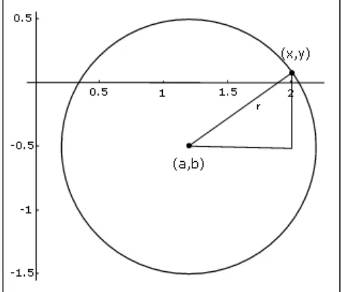
A circle is a plane figure limited by one line which is known as the circuit, and is with the end goal that every straight line drawn from a specific point inside the figure to the boundary are equivalent to another.
In the event that we now square this equation on the two sides, we have: c2= (x−a) 2+ (y−b) 2
Keep in mind that the distance between the center (a, b) and any point (x,y) on the circle is that settled distance, which is known as the radius. So how about we change this equation so it employments r rather than c
r2= (x−a) 2+ (y−b) 2
This is the general formula for a circle with center (a, b) and radius r. Notice that all we have done is somewhat rearrange the distance formula equation.
Area of the Circle
If r is the radius of the circle, d is the diameter of the circle. Then Area of circle
A=
Hence r =
Heat Transfer with Different Tube Orientation
The tube introduction impacts the diagonal, vertical, and horizontal space between the tubes. At specific course of action, the space is uniform and it might help for a superior heat transfer rate. The temperature contrast between the hot liquid and the chilly liquid additionally impacts the heat transfer rate. Consequently, for the tubes, distinctive introductions 45°, 60°, and 90° are considered to discover heat transfer variety along the tube side and the shell side.
VIII. COMPARISON OF CIRCLE & ELLIPSE BY MINOR & MAJOR AXIS
Finned tube heat exchangers are broadly utilized as a part of numerous mechanical applications, for example, aerating and cooling, concoction handling frameworks, Heat exchangers for refrigeration and away tanks of waste atomic materials and so forth. All in all the expansion of heat transfer from tubes conveying stream of hot liquid to the encompassing chilly gases is achievable by appending varieties of annular fins to the external surface of the tubes.
The choice of a specific sort of fin depends fundamentally on the geometry of this primary surface. Radial or annular fins are a standout amongst the most well-known decisions for improving the heat transfer rate from the essential surface of tube shaped shape. It is notable that the rate of heat transfer from the fin diminishes with the expansion of fin length and subsequently, the whole heat transfer surface of a fin may not be similarly used. Hence, there is a nonstop exertion by the designers to decide the ideal fin that will expand the rate of heat transfer for a predefined fin volume or limit the fin volume for a given heat transfer.
IX. FINDINGS
In introduce work the rate of heat transfer from elliptic fin delineating circular tube was analyzed by test strategy. Fin effectiveness is higher for curved fin than circular fin.
If space limitation is along one specific direction, while the opposite course is moderately unlimited elliptic fins could be a superior decision.
Normally heat transfer co-effective relies on the space, time, flow conditions and liquid properties. In the event that there are changes in environmental conditions, there are changes in heat transfer co-productive and effectiveness too.
Presently a day’s minimal heat exchanger with less weight, cost and space are required in nourishment handling enterprises, concoction businesses and refrigeration units. From space limitation on one side and enough space in opposite ways elliptic fins will be better decision.
X. CONCLUSION
The majority of the engineering issues require elite heat transfer parts with continuously less weights, volumes, obliging shapes and expenses. Broadened surfaces (fins) are one of the heat trading gadgets that are utilized widely to build heat transfer rates. The rate of heat transfer relies upon the surface territory of the fin. Spiral or annular fins are a standout amongst the most prevalent decisions for trading the heat transfer rate from the essential surface of barrel shaped shape. In this paper the heat transfer rate and productivity for circular and curved annular fins were dissected for various natural conditions. Curved fin productivity is more than circular fin. On the off chance that space limitation is there along one specific course while the opposite bearing is generally unlimited circular fins could be a decent decision.
At the point when segmental baffles are utilized as a part of STHE which have numerous detriments , the low heat transfer is accomplished because of the flow stagnation, i.e., no man's lands which are made at the corners between the baffle and the shell divider . It requires higher pumping power, and it makes a high pressure drop under a similar heat load.
The execution of the fin communicated as far as fin productivity as curves known as the fin-proficiency curves for various kinds of fins. These curves have been gotten in view of steady convection heat transfer coefficient differential equation for annular fins of uniform thickness. It is exhibited that inexact investigative temperature profiles and heat transfer rates of good quality are effectively realistic without falling back on the correct logical temperature dispersion and heat transfer rate encapsulating adjusted Bessel capacities. For improved representation, the registered temperature profiles, tip temperatures and fin efficiencies of inexact nature are charted and arranged for reasonable mixes of the standardized radii proportion and the thermo-geometric fin parameter of enthusiasm for thermal engineering applications.
REFERENCES
[1] Bell, KJ. (1963) Final report of the cooperative research programme on shell and tube heat exchangers, University of Delaware, Engineering Experimental Station, Bulletin No. 5.Google Scholar
[2] Gay, B, Mackely, NV, & Jenkins, JD. (1976). Shell-side heat transfer in baffled cylindrical shell-and-tube exchangers-an electro chemical mass transfer modelling technique. International Journal of Heat and Mass Transfer, 19, 995–1002.View ArticleGoogle Scholar
[3] Halle, H, Chenoweth, JM, &Wabsganss, MW. (1988). Shell side water flow pressure drop distribution measurements in and industrial sized test heat exchanger. Journal of Heat and Mass Transfer, 110, 60–67.Google Scholar
[4] Huang, X, Lu, Z, & Wang. (2001). Numerical modelling of the shell side flow in the shell and tube heat exchanger. In W. Liu (Ed.), Proc. Int. Conf. on energy Conversion and application volume I, Wuhan, China (pp. 301–304).Google Scholar
[5] Kern, DQ. (1950a). Process heat transfer (pp. 127–171). New York: Mc-Graw-Hill.Google Scholar [6] Kern, DQ. (1950b). Process heat transfer. New York: McGraw-Hill.Google Scholar
[7] Lei, YG, He, YL, Pan, C., et al. (2008). Design and optimization of heat exchangers with helical baffles.Chemical Engineering Science, 63(17), 4386– 4395.View ArticleGoogle Scholar
[8] Li, HD, &Kottke, V. (1998a). Effect of leakage on pressure drop and global heat transfer in shell and tube heat exchanger for staggered tube arrangement. International Journal of Heat and Mass Transfer, 41(2), 425–433.View ArticleGoogle Scholar
[9] Li, HD, &Kottke, V. (1998b). Visualization and determination of local heat transfer coefficient in shell and tube heat exchangers for staggered tube arrangement by mass transfer measurements.Experimental Thermal and Fluid Science, 17(3), 210–216.View ArticleGoogle Scholar
[10] Li, H, &Kottke, V. (1998c). Effect of baffle spacing on pressure drop and local heat transfer in shell and tube heat exchangers for staggered tube arrangement. International Journal of Heat and Mass Transfer, 41(10),1303–1311.View ArticleGoogle Scholar
[11] Li, HD, &Kottke, V. (1998d). Visualization and determination of local heat transfer coefficient in shell and tube heat exchangers for staggered tube arrangement by mass transfer measurements.Experimental Thermal and Fluid Science, 17, 210–216.View ArticleGoogle Scholar
[12] Master, BI, Chunangad, KS, Boxma, AJ, Kral, D, &Stehlik, P. (2006). Most frequently used heat exchangers from pioneering research to world wide applications. Heat Transfer Engineering, 27(6), 4–11.View ArticleGoogle Scholar
[13] Mukherjee, R. (1992). Use double-segmental baffles in the shell-and-tube heat exchangers. Chemical Engineering Progress, 88, 47–52.Google Scholar [14] Palen, JW, &Taborek, J. (1969). Solutions of shell side flow pressure drop and heat transfer by stream analysis method. Chemical Engineering Progress
Symposium Series, 65, 53–63.Google Scholar
[15] Pekdemir, T, Davies, TW, Haseler, LE, & Diaper, AD. (1994). Pressure drop measurements on the shell side of a cylindrical shell and tube heat exchanger. Heat Transfer Engineering, 15, 42–56.View ArticleGoogle Scholar
[16] Peng, B, Wang, QW, Zhang, C., et al. (2007). And experimental study of shell and tube heat exchanger with continuous helical baffles. Journal of Heat Transfer, 129, 1425–1431.View ArticleGoogle Scholar
[17] Qian, SW. (2002). Handbook for heat exchanger design. Beijing: Chemical Industry Press (in Chinese).Google Scholar
[18] Rhodes, DB, & Carlucci, LN. (1983). Predicted and measured velocity distributions in a model heat exchanger. In Int. Conf. on numerical methods in engineering Canadian nuclear society/American nuclear society (pp. 935–948).Google Scholar
[19] Seemawute, P, &Eiamsa-ard, S. (2010). Thermo hydraulics of turbulent flow threw a round tube by a peripheral-cut twisted tape with analternate axes. International Communications in Heat and Mass Transfer, 37, 652–659.View ArticleGoogle Scholar
[20] Stevanovic, Z, Ilic, G, Radojkovic, N, Vukic, M, Stefanovic, V, &Vuckovic, G. (2001). Design of shell and tube heat exchanger by using CFD technique— part one: thermo hydraulic calculations.Mechanical Engineering, 1(8), 1091–1105.Google Scholar
[21] Tinker, T. (1951). Shell side characteristics of shell and tube heat exchangers, parts I, II, and III (pp. 97–116). London: General Discussion on Heat Transfer Inst. Mech. Eng.Google Scholar