www.adv-radio-sci.net/12/61/2014/ doi:10.5194/ars-12-61-2014
© Author(s) 2014. CC Attribution 3.0 License.
FPGA implementation of trellis decoders for linear block codes
S. Scholl1, E. Leonardi2, and N. Wehn1
1Microelectronic Systems Design Research Group, University of Kaiserslautern, 67663 Kaiserslautern, Germany 2Institute of Informatics, Federal University of Rio Grande do Sul, 91501970 Porto Alegre, Brazil
Correspondence to: S. Scholl ([email protected])
Received: 13 December 2013 – Accepted: 5 February 2014 – Published: 10 November 2014
Abstract. Forward error correction based on trellises has been widely adopted for convolutional codes. Because of their efficiency, they have also gained a lot of interest from a theoretic and algorithm point of view for the decoding of block codes. In this paper we present for the first time hardware architectures and implementations for trellis de-coding of block codes. A key feature is the use of a sophis-ticated permutation network, the Banyan network, to ment the time varying structure of the trellis. We have imple-mented the Viterbi and the max-log-MAP algorithm in dif-ferent folded versions on a Xilinx Virtex 6 FPGA.
1 Introduction
Forward error correction is widely used in today’s commu-nication systems for the correction of transmission errors. In the last years and decades many different error correc-tion schemes have been introduced and successfully adopted in various communication standards. Prominent examples for channel codes are convolutional codes, Reed-Solomon codes, turbo codes and LDPC codes.
The optimal correction strategy is called maximum like-lihood (ML) decoding. Since ML decoding is very complex for many practically used codes, most of the decoding al-gorithms are suboptimal heuristics, e.g. the turbo decoding algorithm (Lin and Costello, 2004). However, in this paper we consider two algorithms, that can efficiently perform ML decoding of convolutional codes or small block codes: the Viterbi algorithm (VA) (Viterbi, 1967) and the BCJR algo-rithm (Bahl et al., 1974).
The efficiency of the VA and BCJR algorithm originate mainly in the exploitation of the code’s structure, which is graphically represented as a trellis diagram. In the past a vast amount of research has been carried out on trellis based
de-coding for convolutional codes, including works from gen-eral theory to hardware implementations for real world ap-plications.
However, not only convolutional codes can be described by trellis diagrams. Also block codes can be represented as trellis and thus efficient decoding algorithms for convolu-tional trellises can also be applied to block codes. Trellis de-coders for block codes have many different applications as standalone ML decoder or as components of larger decoding heuristics. Here we want to point out just a few use cases:
– as a maximum likelihood decoder for small block codes
– as a component decoder for turbo product codes, Pyn-diah et al. (1994)
– as a check node decoder for generalized LDPC codes, Tanner (1981)
– as a component for soft decision decoding of Reed-Solomon codes, e.g. in Vardy and Be’ery (1991), Liu and Lin (2004)
Trellises of block codes mostly have a special struc-ture (called time varying trellis), that poses a major chal-lenge for the hardware designer. So far hardware architec-tures and implementations have not been considered yet. In Kim et al. (2003) a trellis decoder was implemented on an FPGA, but its use is restricted to a small group of block codes, that do not have a time varying structure.
a Virtex 6. To our best knowledge, this is the first hardware implementation of trellis decoding for arbitrary block codes. The paper is structured as follows: in Sect. 2 we first present the construction rules for a trellis, followed by a brief description of the algorithms in Sect. 3. Section 4 describes the proposed architectures and the implementation results can be found in Sect. 5.
2 Trellis construction for block codes
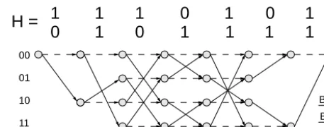
We consider a binary block code with block length N and K information bits. The code is defined by its parity check matrix (PCM) H of dimension (N−K)×N. The columns of H are denoted by hk. A valid code word is denoted by x=(x0, x1, ..., xN−1)and the received log-likelihood ratios (LLRs) by y=(y0, y1, ..., yN−1)
A trellis diagram is a graphical representation of the code word space of a channel code. Every path in a trellis connect-ing the startconnect-ing and end point correspond to exactly one code word.
The trellis diagram for block codes can be constructed in two different ways: using the generator matrix or the parity check matrix (PCM) of the code.
The first construction method is based on the generator matrix (see Lin and Costello (2004) for more information). Since this construction method is quite complex and requires the generator matrix to be in a special form (trellis oriented generator matrix form), we apply the second construction method based on the PCM.
The PCM method provides full flexibility on the matrix, so that any PCM can be used. Furthermore, the trellis struc-ture can easily be deduced from the PCM, which makes it suitable for a hardware implementation. Since the trellis de-scribes a block code, we call it a bit-level trellis – in contrast to the convolutional trellis. In the following we describe the construction method of Wolf (1978).
The bit-level trellis hasN trellis steps (sometimes called time steps), and M=2N−K states per step. The states are labelled by a binaryN−Ktuple smk, wherem=0,1, ..., M−
1 denotes the index of a state in stepk=0,1, ..., N.
To construct the trellis, the states between stepkandk+1 are connected by branches. There are two different types of branches. One corresponds to code bit ’0’ (xk=0) the other one to code bit ’1’ (xk=1). The branches are established recursively as follows: From each state smk of step k two branches depart to state
smk+1=smk for xk=0 slk+1=smk +hk for xk=1
Since only paths from s00to s0Nrepresent code words, all other paths can be expurgated.
There are some remarkable differences between a convolu-tional trellis and a bit-level trellis. A bit-level trellis is in
gen-1
1
1
0 1
0 1
0
1
0
1
1 1 1
H =
00
01
10
11
Bit = 0 Bit = 1
Figure 1. Example for a trellis construction using the PCM H
eral a time-varying trellis, i.e. state transitions change over time – in contrast to the convolutional trellis.
Besides the time varying property, in a bit-level trellis only one bit is associated with a time step. In a convolutional trel-lis usually two or more bits correspond to one time step.
Additionally, it should be pointed out that the “0” branches always connect states having the same label. This property can be exploited in hardware, as we will see later.
A small example forN=7 andK=5 with aM=4 state trellis is depicted in Fig. 1 to clarify the trellis construction.
3 Trellis decoding algorithms
Once the trellis representation of a code is obtained, it en-ables the use of very efficient decoding algorithms, like the VA and the BCJR algorithm. In this section we give a short summary of these two algorithms for bit-level trellises and their variants in the log domain.
3.1 Viterbi algorithm
The VA (Viterbi, 1967) performs ML decoding efficiently on a trellis. It looks for the most probable path in the trellis by recursively building up paths through the trellis and discard-ing unlikely paths in every step. We shortly repeat the VA in the logarithm domain, that is usually used for hardware implementation.
For the VA every trellis state smk is assigned a state metric α smk. The state metrics for stepkare calculated recursively from those of stepk−1.
1. initialize the state metrics at step 0: s00 with 0 and all other sm0 (m6=0) with -infinity
2. For all states k=1, .., N−1 and all indices m=
0,1.., M−1 calculate
αslk=maxhαsk−l 1, α smk−1+yk−1
i
(1)
where slk=smk−1+hk−1
More detailed information on the VA can easily be found in literature (Lin and Costello, 2004; Wolf, 1978).
3.2 BCJR and Max-log-MAP algorithm
A drawback of the VA is that it does not provide any soft output information, which is required by modern decoding heuristics. However, the BCJR algorithm (Bahl et al., 1974) provides such additional information.
For hardware implementations is it advantageous to use the BCJR algorithm in the logarithm domain, which is called log-MAP, or its low complexity version max-log-MAP (Robertson et al., 1995). In this paper we consider the max-log-MAP, because it provides low complexity without de-grading the decoding performance significantly.
In the max-log-MAP (and also the BCJR algorithm) every state is assigned two state metrics: the forward state metrics α smkand the backward state metricsβ smk.
Max-log-MAP decoding consists of three phases: 1. forward recursion (calculates state metricsα smk) 2. backward recursion (calculates state metrics (β smk
) 3. soft output calculation (usingα smk,β smk+1andyk)
The forward recursion is equal to that of the VA in Eq. (1). For the backward recursion the states are processed in re-versed order, i.e. from right to left. Details of the algorithm can be found e.g. in Lin and Costello (2004).
It can already be seen, that the recursion steps are im-portant in both the VA and the max-log-MAP. It consists of add-compare-select (ACS) operations in Eq. (1) and requires permutations of state metrics according to the time varying branch structure. In the following section, we will focus on the hardware architecture for such a recursion unit for bit-level trellises.
4 Proposed architectures
In this section we present the hardware architectures for the VA and the max-log-MAP decoder for bit-level trellises. We propose the use of a Banyan network to implement the flexi-ble state transitions. Finally we present a folded architecture, which reduces the decoder area to enable the implementation for trellises with a large number of states.
4.1 Architectures for Viterbi and Max-Log-MAP algorithm
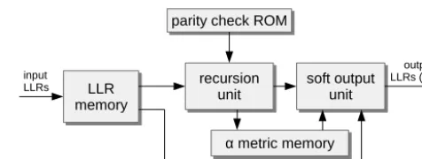
The top level architectures for Viterbi and max-log-MAP de-coder are depicted in Figs. 2 and 3. Although they look dif-ferent, their core functionality is the recursion unit, which is identical in both cases.
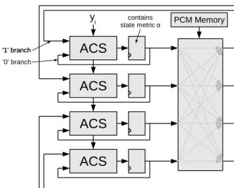
The recursion unit for a simple case of a 4 state trellis is shown in Fig. 4. All state metricsα smkof one time stepkare
recursion unit recursion
unit survivor bitmemory survivor bit memory parity check ROM parity check ROM
traceback unit traceback
unit input
LLRs outputbits
Figure 2. Top level architecture of the Viterbi decoder
recursion unit recursion
unit
α metric memory α metric memory parity check ROM parity check ROM
soft output unit soft output
unit input
LLRs
output LLRs (APP) LLR
memory LLR memory
Figure 3. Top level architecture for the max-log-MAP decoder
calculated in parallel. The different trellis steps are calculated consecutively, i.e. one trellis step per clock cycle. The state metrics are temporarily stored in the registers.
One iteration consists of routing the state metrics through the permutation network first. The routing is done accord-ing to the branch structure of the trellis and is determined by the columns of the PCM hk. Then the ACS units calcu-late Eq. (1). Finally the state metrics are stored in the register again.
Note, that the state metrics are directly fed back to the ACS units. This maps the branches for code bit ’0’ to the hard-ware.
The state metrics and received LLRs y are represented as fixed point numbers. To keep the number of bits low and therefore to save resources without provoking catastrophic overflows, modulo arithmetic is used here (Hekstra, 1989). 4.2 Permutation network
An essential part of the trellis decoders is the permutation network (PN). It routes the state metrics along the Bit “1” branches during the recursion.
The PNs in the trellis decoders must haveM=2N−K in-puts and outin-puts. The network is controlled by the column bits of the PCM hkand consists of 2×2 butterfly switches, which can permute or route through its two inputs.
We first investigate the use of the well known Benes PN (Benes, 1964) and in a second step propose the use of a more sophisticated network, the Banyan PN (Goke and Lipovski, 1973).
The Benes PN is capable of performing all possibleM!
ACS
ACS
ACS
ACS
PCM Memory contains
state metric α
'1' branch '0' branch '1' branch
yi
Figure 4. Architecture of the recursion unit
the maximum combinational path of the recursion unit and thus decreases the throughput. Furthermore the Benes PN requires a complex controlling logic, which maps the bits from the PCM to the control bits of the switches, see Fig. 7.
The second network studied is the Banyan PN. It performs the necessary permutation with approximately half the num-ber of stages (log2(M)) in comparison to the Benes PN. This reduces the signal propagation time and improves through-put. Moreover the Banyan PN has approximately half the number of switches (see Fig. 5). Another advantage is that the bits of the columns of the PCM can directly be applied to control the switches in the network. No extra controlling logic is required. The small number of switches and the sav-ing of the complex controllsav-ing logic makes the Banyan PN the network of choice for this application.
In the following, we provide our method of how to build up such a network. The Banyan PN is constructed from two But-terfly PNs and a final permutation stage. The smallest Butter-fly PN is composed of a single switch and larger ones can be constructed recursively, i.e. a network with Minputs is ob-tained from two Butterfly PNs withM/2 inputs.
We place the second Butterfly PN below the first one and denote the outputs byS(i)withi=0,1, .., M/2−1 andi=
M/2, .., M−1. The final stage is a column ofM/2 switches that placed right of the two Butterfly PNs. Their inputs are denoted byI (i)withi=0,1, .., M−1 and their outputs by B(i). The connections between the two Butterfly PNs and the final stage is done by the following algorithm:
Finally, we connect the outputsB(i)of the final stage to the outputsO(i)of the Banyan PN by using the following algo-rithm:
Each input of the network has to be able to reach all the M different output addresses and that is only possible with N−Kstages. Thus it is impossible to do all the required per-mutations with a network with less stages than the Banyan.
Algorithm 1. Intermediate connections of a Butterfly PN. Algorithm 1: Intermediate connections of a Butterfly PN
for (i = 0 to (M/4 -1)) do
I(2∗i) ← S(2∗i)
I(2∗i + 1) ← S(2∗i + M/2)
I(2∗i + M/2) ← S(2∗i + 1)
I(2∗i + M/2 + 1) ← S(2∗i + M/2 + 1) end for
Algorithm 2. Output connections of a Banyan PN.
Algorithm 2: Output connections of a Banyan PN for (i = 0 to (M/2 -1)) do
O(i) ← B(2∗i)
O(i + M/2) ← B(2∗i + 1) end for
Figure 6 shows the construction of an 8×8 Banyan PN using the algorithms from above.
4.3 Folding
For trellises with a large number of statesM, the above pre-sented architecture grows quickly and may become too large for an FPGA implementation. To counteract this problem, we propose folding to reduce the required resources of the decoder at the expense of a reduced throughput.
In the folded architecture not allM state metrics in one trellis step are calculated in one clock cycle. Instead the state metrics are calculated, e.g. in two clock cycles. In this case half of the ACS units can be reused.
Furthermore it reduces the size of the PN by more than half given that its construction is recursive (see above). Note, that the folded Banyan PN withM/2 exactly fulfils the per-mutation requirements of the folded architecture, and is thus suitable for folded architectures.
The number of clock cycles required to calculate the state metrics of one trellis step is called folding factorf and must be a power of 2.
Due to folding the size of the PN, the number of ACS units and the soft output unit (for the max-log-MAP decoder) is largely reduced. However, some additional hardware re-sources are needed to distribute the state metrics to the PN and ACS units and registers to store the partially calculated state metrics.
The area reduction of the soft output unit is directly pro-portional to the folding factorf. Therefore folding is espe-cially advantageous for the max-log-MAP decoder.
5 FPGA implementation
S. Scholl et al.: FPGA implementation of trellis decoders for linear block codes 65 bits of the PCMhkand consists of2×2butterfly switches,
which can permute or route through its two inputs.
We first investigate the use of the well known Benes PN (Benes (1964)) and in a second step propose the use of a more 220
sophisticated network, the Banyan PN (Goke and Lipovski (1973)).
The Benes PN is capable of performing all possibleM! permutations, although in this application only M are re-quired. Therefore, the Benes PN uses more resources than 225
necessary. A drawback of the Benes PN is its elevated num-ber of2·log2(M)−1 stages, which directly lengthens the
maximum combinational path of the recursion unit and thus decreases the throughput. Furthermore the Benes PN re-quires a complex controlling logic, which maps the bits from 230
the PCM to the control bits of the switches, see Fig. 7. The second network studied is the Banyan PN. It performs the necessary permutation with approximately half the num-ber of stages (log2(M)) in comparison to the Benes PN. This
reduces the signal propagation time and improves through-235
put. Moreover the Banyan PN has approximately half the number of switches (see Fig. 5). Another advantage is that the bits of the columns of the PCM can directly be applied to control the switches in the network. No extra controlling logic is required. The small number of switches and the sav-240
ing of the complex controlling logic makes the Banyan PN the network of choice for this application.
In the following, we provide our method of how to build up such a network. The Banyan PN is constructed from two But-terfly PNs and a final permutation stage. The smallest Butter-245
fly PN is composed of a single switch and larger ones can be constructed recursively, i.e. a network withM inputs is ob-tained from two Butterfly PNs withM/2inputs.
We place the second Butterfly PN below the first one and denote the outputs byS(i)withi= 0,1, .., M/2−1andi=
250
M/2, .., M−1. The final stage is a column ofM/2switches that placed right of the two Butterfly PNs. Their inputs are denoted byI(i)withi= 0,1, .., M−1and their outputs by
B(i). The connections between the two Butterfly PNs and the final stage is done by the following algorithm:
255
Algorithm 1Intermediate connections of a Butterfly PN
for(i= 0 to (M/4−1))do
I(2∗i)←S(2∗i)
I(2∗i+ 1)←S(2∗i+M/2)
I(2∗i+M/2)←S(2∗i+ 1)
I(2∗i+M/2 + 1)←S(2∗i+M/2 + 1)
end for
Finally, we connect the outputsB(i)of the final stage to the outputsO(i)of the Banyan PN by using the following algorithm: 0 200 400 600 800 1000 1200 1400 1600 1800 2000
8 16 32 64 128 256
Number
of
switch
es
Number of inputs Benes
Banyan
Fig. 5.Number of switches used by the Benes and the Banyan PN
Control bits from PCM
Butterfly PN
Butterfly PN
Fig. 6.Eight input Banyan PN: it needs less switches than the Benes PN and no controlling is needed
Algorithm 2Output connections of a Banyan PN
for(i= 0 to (n/2−1))do
O(i)←B(2∗i)
O(i+n/2)←B(2∗i+ 1)
end for
Each input of the network has to be able to reach all the
M different output addresses and that is only possible with 260
N−Kstages. Thus it is impossible to do all the required per-mutations with a network with less stages than the Banyan.
Fig. 6 shows the construction of an 8x8 Banyan PN using the algorithms from above.
4.3 Folding
265
For trellises with a large number of statesM, the above pre-sented architecture grows quickly and may become too large for an FPGA implementation. To counteract this problem, we propose folding to reduce the required resources of the decoder at the expense of a reduced throughput.
270
Figure 5. Number of switches used by the Benes and the Banyan
PN
Control bits from PCM
Butterfly PN
Butterfly PN
Figure 6. Eight input Banyan PN: it needs less switches than the
Benes PN and no controlling is needed
resource consumption regarding the required look-up tables (LUTs) after place & route.
The numbers presented are only dependent on the num-ber of trellis statesMand not on the number of trellis steps N. The number of trellis stepsN only influences the size of the memories. However this is not the critical resource in the design.
The quantization of the metrics is dependent on the context in which the decoders are used. However it has been experi-enced by simulations that a state metric quantization of 7 Bits for the VA and 8 bits for the max-log-MAP is reasonable.
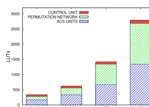
In Figs. 8 and 9 the required LUTs for the unfolded archi-tecture (f =1) is shown, separated for each decoder part.
For the VA almost 50 % of the LUTs are occupied by the ACS units. The PN also consumes nearly 50 % of the LUTs. Therefore the ACS units and the PN are the dominating parts.
Complex Controlling Logic
Bits from PCM memory
Figure 7. Eight input Benes PN: it needs more switches than the
Banyan PN and additional controlling is needed
0 500 1000 1500 2000 2500 3000
8 16 32 64
LU Ts Trellis states CONTROL UNIT PERMUTATION NETWORK ACS UNITS
Figure 8. Viterbi decoder: look-up tables
The remaining fraction is occupied by the controlling, which also includes the traceback unit.
The max-log-MAP is dominated by the soft output unit, which needs approximately 50 % of all LUTs. The PN and the ACS units consume around 25 % each.
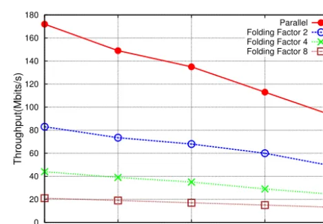
In Figs. 10 and 11 the number of required LUTs for dif-ferent folded architectures are shown. It shows how the oc-cupied resources reduce and allows for the implementation of larger trellises. The throughput decrease for the VA can be seen in Fig. 12.
6 Conclusions
0 1000 2000 3000 4000 5000 6000 7000
8 16 32 64
LU
Ts
Trellis states CONTROL UNIT
ACS UNITS PERMUTATION NETWORK SOFT OUTPUT UNIT
Figure 9. Max-log-MAP decoder : look-up tables
0 2000 4000 6000 8000 10000 12000 14000
32 64 128 256
LUTs
Trellis states Parallel
Folding Factor 2 Folding Factor 4 Folding Factor 8
Figure 10. Viterbi decoder: LUTs dependent on folding factor
feature is the Banyan PN, which maps the time variant prop-erty of the trellis efficiently to hardware and significantly out-performs standard solutions like the Benes PN. Furthermore we presented a folded version of the architecture to enable the implementation for large trellises. Finally the resource consumption and throughput of the architecture have been evaluated on a Xilinx Virtex 6 FPGA.
Acknowledgements. We gratefully acknowledge partially financial
support by the DFG (project-ID: KI 1754/1-1) as well as by the Center of Mathematical and Computational Modelling of the University of Kaiserslautern. We thank F. Kienle for his valuable comments and suggestions.
Edited by: J. Götze
Reviewed by: two anonymous referees
0 5000 10000 15000 20000 25000 30000
32 64 128 256
LUTs
Trellis states
Parallel Folding Factor 2 Folding Factor 4 Folding Factor 8
Figure 11. Max-log-MAP decoder: LUTs dependent on folding
fac-tor
0 20 40 60 80 100 120 140 160 180
16 32 64 128 256
Throughput(Mbits/s)
Trellis states
Parallel Folding Factor 2 Folding Factor 4 Folding Factor 8
Figure 12. Viterbi decoder: throughput dependent on folding factor
References
Bahl, L., Cocke, J., Jelinek, F., and Raviv, J.: Optimal Decoding of Linear Codes for Minimizing Symbol Error Rate, IEEE T. In-form. Theory, IT-20, 284–287, 1974.
Benes, V. E.: Optimal Rearrangeable Multistage Connecting Net-works, The Bell System Technical Journal, 4, 1641–1656, 1964. Goke, L. R. and Lipovski, G. J.: Banyan Networks for Partitioning Multiprocessor Systems, 1st Annual Symposium on Computer Architecture, 21–28, 1973.
Hekstra, A. P.: An Alternative to Metric Rescaling in Viterbi De-coders, IEEE T. Commun., 37, 1220–1222, 1989.
Kim, S., Ryoo, S., and Lee, S.: Block Turbo Codes Using Multiple Soft Outputs, in: Proceedings of the 3rd ISTC, Vol. 1, 247–250, Brest, 2003.
Lin, S. and Costello, D.: Error Control Coding 2nd., Prentice Hall PTR, Upper Saddle River, New Jersey, USA, 2004.
Pyndiah, R., Glavieux, A., Picart, A., and Jacq, S.: Near optimum decoding of product codes, in: Proc. IEEE Global Telecommuni-cations Conf. GLOBECOM ’94. CommuniTelecommuni-cations: The Global Bridge, 339–343, 1994.
Robertson, P., Villebrun, E., and Hoeher, P.: A Comparison of Op-timal and Sub-OpOp-timal MAP decoding Algorithms Operating in the Log-Domain, in: Proc. 1995 International Conference on Communications (ICC ’95), 1009–1013, Seattle, Washington, USA, 1995.
Tanner, R. M.: A Recursive Approach to Low Complexity Codes, IEEE T. Inform. Theory, IT-27, 533–547, 1981.
Vardy, A. and Be’ery, Y.: Bit-level soft-decision decoding of Reed-Solomon codes, IEEE T. Commun., 39, 440–444, 1991. Viterbi, A. J.: Error Bounds for Convolutional Codes and an
Asymptotically Optimum Decoding Algorithm, IEEE T. Inform. Theory, 13, 260–269, 1967.