LAUTECH JOURNAL OF ENGINEERING AND TECHNOLOGY 3(1) 2005: 5 - 11
LINEARISATION TECHNIQUES:
THE KEY TO THE USE OF MORE
EFFICIENT MODULATION SCHEMES
AND RF POWER
AMPTIFIERS
J.A. Ojol and O. Adegbenro
lDepartment
of Etectronic & Electricel Engineering, Ladoke Aklntole Univerelty of Technotogy,
2Deparrment"r",.J;f.",J$li;fii':$ll":.'::l'J',TffhorLagos,Nigeria.
ABSTRACTI
This paper gives e brief description of linear modulation schemes and how they are more etlicient for daa communicalion. Different classes of RF. power ampliJiers with respect to their elficiencies are also
discussed, ss weII as different linearisation techniques presently in use and those at the Research and Developmental stage. This paper illustrutes with *amples how more elJicient modulation schemes and morc eJlicient classes of RF power amplifrerc cqn be adopted for use in data communications, il the inherent probkm of spectral spreading, whlch results from non-linesr ourput of RF power amplifiers at the front end of devices can be effeuively hsndled.
INTRODUCTION
Radio frequency (RF) spectrum is a natural 'scarce' resource and in recent times has become more expensive, therefore has to be used wisely. New innovations and recently developed services have created tlre need for increased data rate capability, resulting to the need for larger bandwidth for wireless operators. In addition, there is a need to ensure that all services can co-exist without causing harmful interference to one another. To avoid interference, sufficient guard bands have to be introduced between operators' allocated frequencies and this in itself ,results in inefficient use of the RF spectrum. To optimise the use of the frequency spectrum in meeting the explosive demands for high-speed data rates, there is a need to develop a more spectrally efficient system (modulation scheme and front-end devices). Thus, there is the need for a change from the old, less e{ficient modulation schemes to high data rate multi-level modulation schemes, which provide inherently greater data rates for a given bandwidth. In mobile radio systems, interest has been focused on Gaussian Phase Shift Keyng (GPSK), Quadrature Phase Shift Kelng (QPSK) and Quadrature Amplitude Modulation (QAM) with specific interest in the I6-QAM and pi/4 - QPSK. However, the u se of I inear m odulation techniques has not been fully embraced due to the effect ofthe front-end devices that may cause distortions, especially in the RF mixers and power amplifiers.
The mostly used forms of Radio Frequency (RF) linear amplifier are the ciass-A, class-B and class-AB, whereas these classes of amplifiers are not the most efficient form of amplifiers available. The more efficient RF power
amplifiers, however, have non-linear rgsponse. These can result in unacceptable generation of signals o utside the allocated frequency c hannel o r band (i.e. spectral spreading), which is referred to as Spectral Re-growth and can lead to Co-channel Interference (ifthe guard band between channels is small, the spectral re-growth will interfere with the signal quality in the adjacent channels). As a result, specific spectral constraints (performance specifications) have to be placed on RF users to avoid interference. The use of linear modulation schemes in mobile communication, therefore, requires the use of highly linear RF amplifiers and some form of linearisation technique.
Linearisation is a systematic procedure for reducing amplifier's distortion, it allows an amplifier to produce more output power and operate at a higher level of efficiency. The most common forms of linearisation are the feedforward, the feedback and the predistortion techniques, while other forms are still in the research stage.
J.A. Ojo and O. Adegbenro/LAUTECH Journal of Englneerlng and Technology 3(1) 2U)5: 5 - 11 '
BACKGROUND
The increasing demand for h igh-data-r'ate wireless applications has led the development and use of spectrally efficient modulation schemes. It was reported in [1] that DMC Stratex Netrvorks developed an STM-l/0C3 128QAM point-to-point radio that uses half the b andrvidth o f any existing radios at 18 GHz and above. Also. a more spectrally efficient dc-free modulation scheme called Hierarchical QAM (HQAM), a modulation scheme that uses QAM modulation in two stages was proposed in [2]. In [3], a review of amplifier configurations, classes of operation, device characterisation and example applications was presented, where only class-A amplifier is classified as having a linear output but with low efficiency of 50%, while the more efficient ones produce non'linear outputs. To reduce the distortion introduced by non-linear amplifiers, different linearisation methods have been developed.
The most commonly used forms of linearisation are the Feedforward, the Feedback and the Predistortion techniques while others are in the Research and Development (R&D) stages [4,5,6]. The Feedback technique (Cartesian loop transmitter) has been widely applied in wireless and microwave applications. Other methods still in the Research and Development (R&D) stages generally referred to as Synthesis techniques. are Linear Amplification Using Non-linear Components (LINC) and the Combined Analogue-Locked Loop Universal Modulator (CALLUM), [7,8,9]. Mann et al [0] described the effect of power efficiency of the RF transmitter stage in mobile handsets on the battery capacity as rvell as talk-tirne between battery recharge cycles.
LINEAR MODUI.ATION SCHEMES
Linear modulation schemes can be defined as those in which information is transmitted in both the amplitude and the phase of the carrier signal. The envelope ofthe RF signal produced by these modulation schemes varies with time; therefore, the ehvelope must be preserved in order to be able to recover the full information content of the original signal after processing or transmissron. One of such nrodulation schemes, l6-QAM, is discussed in this paper.
Complex envelope representation of modulated signals.
All bandpass wavefbrms, whether they arise from a modulated signal or noise may be represented in a convenient form given by:
( . . . . 1
V (t) = Re{g(r)e''"''
}
rrt
where w" : 2nf,, f. is the baseband carrier frequencyRe{*} indicates the real part of V(t) , while g(t) is the complex envelope of V(t)
r . e . V ( t ) = R ( r ) c o s [ w . t + 0 ( ) ] Q )
0(t) represents any variation in the phase.
Also in Cartesian form, a modulated signal can be represented as
V (t) = x(.t) cosw,t
- y(r) sin w, t
(3)
given
that g(t) =.x0) + iy(t) = R(t)eiqu)
rvhere
x(l) = Re{g(r)}= R(r)cosd(l)
v(t) = Im{g(r)}=
R(/)sin9(r)
R0) -) lg(r)l =
, / . \
o(t) = ts(t) = tan-'[
42 ]
t .x(/)
/
Quadrature Amplitude ModulationQuadrature Amplitude Modulation (QAM) can be described as a combination of AM and PIv{ modulation schemes. It provides a good combination of high data rates (twice the rate of standard PAM), efficient use of available bandu idth, low bit error rates as well as easy denrodulation of RF (earlier modulated) signal. It can be interpreted as a single carrier that is both amplitude and phase modulated or two carriers of identical frequency, but one is exactly 900 out of phase with respect to the other.
QAM complises of two components: the in-phase (I) component and the quadrature (Q) component, which is at 90u phase shift with respect to the I-component. it can be represented mathematically as:
S(t) = I(t) + 80
G)
S(l; = x(l) cos w.l - y(t)sinw,t
By trigonometry;
r
- . . t
J(t1 = .4(/)costtr.l
+ o(/)l
(s)
This can be interpreted
as a single
carrier
with fixed frequency but variable amplitude and phase.
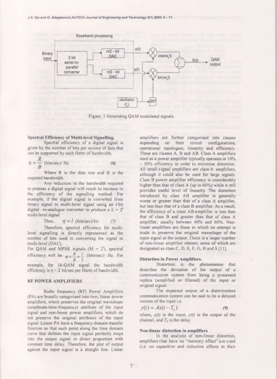
In QAM, each carrier is modulated to one of several permitted (digital) levels. With n distinct levels for each carrier, a total ofn 1 n = (n') unique digital states can be represented. By using two (n/2 : 2) bit digital-to-analogue converters and quadrature modulator a 16-symbol (4 x 4) QAM can be generated as shown in Figure I
J.A. Ojo and O. Adegbenrc/LAUTECH Joumal of Engineefing and Teehnology 3(1) 2005: 5 - 11.
Baseband processing
i xttl
Figure. I Generating QAM modulated signals.
Spectral Efficiency of lllulti-level Signalling. Spectral . efficiency of a digital signal is erven by the number of bits per second of data that can be supported by each Hertz ofbandwidth.
oAM
output
ampiifiers are funher categorised into classes depending on their circuit configurations, operational topologies, linearity and efficiency. These are classes A, B and AB. Class A amplifiers - used as a power amplifier typically operates at 70t/o - 30% efficiency in order to minimise distortion. All smail signal amplifiers are classA amplifiers, although it could also be used for large signals. Class B power amplifier efficiency is considerably higher than that of class A (up to 66%) while it still provides useful level of linearity. The distoftion introduced by class AB ampiifier is generally worse or greater than that of a class A amplifier, but less than that of a class B amplifier. As a result, the efficiency of a class AB amplifier is less than that of class B and greater than that of class A amplifier, usually between 40Yo and 60%. Non-linear amplifiers are those in which no attempt is made to preserve the original waveshape of the input signal at the output. There is a larger number of non-linear amplifier classes, some of which are designated as class C, D, E, F, C, H and S [11].
Distortion in Power Amplifiers.
Distortion is the phenomenon that describes the deviation of the output of a communication system from being a processed replica (amplified or filtered) of the input or original signal.
The expected output of a distordonless communication system can be said to be a delayed version ofthe input i.e.
y(t) = Ax(t - 7,,)
(e)
where, x(t) is the input, y(t) is the output of the channel, and ln7 is the delay
Non-linear distortion in amplifiers
In the analysis of non-linear distortion, amplifiers t hat have ng "memory effect" a re u sed (i.e. no capacitive and inductive effects in their
R
n=
B
ftits/sec)/Hz
Where R is the
(6)
data rate and B is the required bandwidth.
Any reduction in the bandwidth required to process a digital signal will resuh to increase in the efficiency of the signalling method. For example, if the digital signal is converted from binary signal to multi-level signal using an /-bit digital -to-analogue converter to produce a L = 2t multi-level signal
Then, ry=l (bitslsecYqz (7) Therefore, spectl'al efficiency for multr-level signalling is directly represented as the number of bits used in converting the signal to multi-level (DAC).
For QAM and MPSK signais (M : 2'), spectral efficiency will be ,=L- ' 8 2 / (bits/sec)l Hz. For
example, for 16-QAM signal the bandwidth efficiency is q - 2 bit/sec per Hertz of bandwidth.
RF POWER AMPLIFIERS
J.A. Ola and O. Adegbenro/LAItTECH Journal ot Englmedng and Technology 3(1) 2$5:5- 11.
circuit) such that the present output is only a function of the present input in the time domain.
i.e.
Vu.ft)
: kvi,ft)
(10)
Where, K is the gain of the amplifier. However, if the amplitude of the input signal is increased, the output of the amplifier saturates at some value and this results in non-linear response. The resulting output-to-input characteristic is usually modelled by Taylor's expansion about zero (Maclaurin series) i.e
. v o w = Ko+ KrV,r + K.VIN + . . . = i X , V ; Q l )
r = 0
Ka is the output dc offset level, K1V6- is the first order (linear) term, K21y'61-is the second order (square-law) term, and K3V'1y is the third order terrn, e.t.c.
The transfer characteristic of an amplifier with a second order (non-linear) factor is given as;
Vo*U) = KrY*(t)+ KrVhQ)
Consider the case of a single sinusoidal tone input r.e. V,r(t) = Aosinwot.- /,
vorrQ) = Krlo sin *ot * ff(l - coszwot)Q2)
In frequency dorniin, this indicates that a second signal component now exists at twice the original frequency (2ws),this isrefened to asthe Second Harmonic Distortion, a form of non-linear distortion. In addition, a dc term also results from the second-order term.
The transfer characteristics of an amplifier with a third order term is given as;
K - t - \
Vour() = K,losin wol + ](,4osin wot - 4 sin3u',,1J
z
(13) There is an addition of a term at three times the original input signal frequency, this is the third harmonic signal and it is generally referred to as the Third Harmonic Distortion,
LINEARISATION TECHNIQUES
Linearisation can be described as a systematic procedure for reducing distortion in amplifiers or mixers. Preceding the use of linearisation techniques, linearity of power amplifiers was achieved at the expense of power effrciency by reducing the signal level to the amplifier such that its output power is well below
its peak power rating (a method termed backing-off). Conversely, linearisation allows an amplifier to produce more oufput power and operate at a higher level of efficiency for a given level of distortion.
Cartesian Loop Transmitter.
The Cartesian loop has complete transmitter architecture and not just a form of correction to a particular amplifier distortion. It is, therefore, less'affected bythe type of amplifier in use or the kind of the distortion the amplifier could have. The principle of operation of the Cartesian loop transmitter can be explained through Figure 2. The baseband or modulating signal is split into quadrature components prior feeding it to the transmitter forming two signal paths, The quadrature components are then fed into differential amplifiers, which form the subtraction that generates error signals from the combination of the feedback signals- and the new sample signals. The eror signal generated is passed through a low pass filter in each quadrature path.
The outputs ofthe filters are up-converted (mixed) to RF using a quadrature RF oscillator (comprising of two carriers of the same frequency but one is 90" out of phase with the other. The resulting RF signals from the two paths are then added to produce a cornplex RF output signal, which is amplified by the non-linear power amplifier.
JA, OF .ttcl O. @tutto/LAUTECH Joumat of Engtrrc.rring end fechnalogy g(1) ?fit5j g - 11.
Ft(s)
Up-Conve/,tel Mixar
Mds) RF Pdrcl
& + : t ^ T t _ j L
2 . 5
sisnat hhn
\
s'El
SIMULATIONS.
This section discusses the results of simulation for a I6-QAM signal of 60kbps (data) rate. figure 3 showsthe complex envelopeof the simulated signal. Figure 4 and Figure 5 dtows the Power Spectral Deusity (PSD) plot of the sme signal amplified by a class A and class C RF porve,r amplifiers, respectively, using the polynomial fit model for the amplifiers [3]. Figure 6shows ttre linearised output (using the Cartesian Loop Transnittsr techniques) of the class-C amplified signal.
Figuro 3: Th€ Plat of Un-arnplified I6-QAM eigrral.
Figure 4: The plo{ of I6QAM signal amplified witJraclassAamplifier
Figure 5: Unlirrcarised output of 16-QAM sigrral . amglified with a class C aurplifier
PIor dUrdbd o^f rrrnll
Seneated ,m*
Fds) '
J.A. Oio and O, Ad6{'ben.olLAUTECH Joumal of &tgircedng .nd Technology 3(1) 2006: 6 - 11,
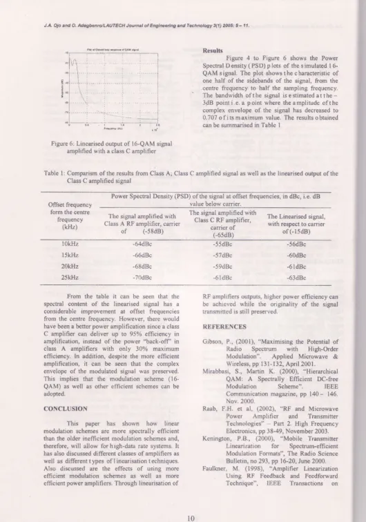
Results
Figure 4 to Figure 6 shows the Power Spectral D ensity ( PSD) p lots of the s imulated I 6-QAMsigral. The plot showsthecharacteristic of one half of the sidebands of the sigral, from the centre frequency to half the sampling frequency. The bandwidth of the signal is e stimated at the -3dB point i.e. a point where the amplitude of the complex envelope of the signal has decreased to 0.707 o f i ts m aximum value. The results o btained can be summarised in Table 1
Figure 6: Linearised output of [6-QAM signal amplified with a class C amplifier
Table l: Comparism of the results from Ciass A; Class C amplified signal as well as the linearised ouput of the Class C amplified signal
Offset frequency form the centre
frequency (kHz)
Power Spectral Density (PSD) of the signal at offset frequencies, in dBc, i.e. dB value below carrier.
rhe signat
amptified
with
t$:#ttr!}:i*:nn
rhe Linearised
signal,
Class A-RF amplifier, carrier "''""
i#"ioitt"tt' with respect to carrier of (-58d8)
(_6sdB) of (l5dB)
1 t . r
l0kHz
l5kHz
20Elz
25lr}lz
-64dBc
-66dBc
-68dBc
-70dBc
-55dBc
-57dBc
-59dBc
-61dBc
-56dBc
-60dBc
-61dBc
-63dBc
From the table it can be seen that the spectral content of the linearised signal has a considerable improvement at offset frequencies from the centre frequency. However, there would have been a better power amplification since a class C amplifier can deliver up to 95% efficiency in amplification, instead of the power "back-off in class A amplifiers with only 30% maximum efficiency. In addition, despite the more efficient amplification, it can be seen that the complex envelope of the modulated signal was preserved. This implies that tlre modulation scheme (16-QAM) as well as other efficient schemes can be adopted.
CONCLUSION
this paper has shown how linear modulation schemes are more spectrally efficient than the older inefficient modulation schemes and, therefore, will allow forhigh-data rate systems, It has also discussed different classes ofamplifiers as well as different t ypes of I inearisation t echniques. Also discussed are the effects of using more efficie$t modulation schemes as well as more efficient power amplifiers. Through linearisation of
RF amplifiers outputs, higher power efficiency can be achieved while the originality of the signal transmited is still preserved.
REFERENCES
Gibson, P., (2001), "Maximising the Potential of Radio Spectrum with High-Order Modulation". Applied Microwave & Wireless, pp l3l-132, April 2001. Mirabbasi, S., Martin K. (2000), "Hierarchisal
QAMr A Spectrally Effrcient DC-free Modulation Scheme".
IEEE
Communication magazine, pp 140- 146. Nov.2000.
Raab, F.H. et al, (2002), "RF and Microwave Power Amplifier and Transmitter Technologies" - Part 2. High Frequency Electronics, pp 38-49, November 2003. Kenington, P.B., (2000), "Mobile Transmitter
Linearization for Spectrum-efficient Modulation Formats", The Radio Science Bulletin, no293, pp 16-20, June 2000. Faulkner, M. (1998), "Amplifier Linearization
Using RF Feedback and Feedforward Technique", IEEE Transactions on
tt Oto d O. ,fr,.,ron-AltfFGH Joumtl ot Eng!rce''ng aN T*hnology 3(1 ) 2ut5: 5 - 1 1 .
Vehicular Technology. Yol 47, no I, pp 20E - 210, February 1998.
ZNosh, F. et al (2000), "Digital Predistortion Linearises RF PAS", Microwave & RF Joumal, August 2000.
trb, F.H. et al, (2002), "RF and Microwave Power Amplifier and Transmitter Technologies" - Part 4. High Frequency Electronics, pp 38-49, November 2003. f&, A. (2001), "Linearization Reducing
Distortion in Power Amplifiers", IEEE Microwave Magazine, pp 37 - 49, Dec. 2001.
bb, F.H. et al, (2002), "Power Amplifiers and Transmitters for RF and Microwave"-IEEE Transactions on Microwave Theory and Techniques, vol. 50, no. 3, pp 814-826, March 2002.
Mann, S., Beach M., Warr P., McGeehan J. (2001), "Increasing the talk-time of mobile radio with efficient linear transmitter
architectwes", Electronics & , Communication Engineering Joumal,
Vol.13, No- 2, pp 65 - 76.
Kenington, P.8., (2000), 'Hieh-Linearitv RF '
Amplifier Desien", ArtechHouse, London, 2000.
Ojo J.A., (2002\, 'Linearisation Techniques For Spectrally Efficient Modulation Formats (Focus on) Cartesian Loop Transmitter', . M.Sc. Thesis, University of Lagos,
Nigeria, November 2002.
Kenington, P.B., (2000), 'High-Linpariry RF Amplifrer Desisr", ArtechHouse, London, 2000.