Energy Procedia 68 ( 2015 ) 326 – 335
ScienceDirect
1876-6102 © 2015 The Authors. Published by Elsevier Ltd. This is an open access article under the CC BY-NC-ND license (http://creativecommons.org/licenses/by-nc-nd/4.0/).
Peer-review under responsibility of Scientific Committee of ICSEEA 2014 doi: 10.1016/j.egypro.2015.03.263
2nd International Conference on Sustainable Energy Engineering and Application, ICSEEA 2014
Electric vehicle mobile charging station dispatch algorithm
Tinton Dwi Atmaja
a,*, Midriem Mirdanies
aaResearch Centre for Electrical Power and Mechatronics, Indonesian Institute of Sciences, Komp LIPI Bandung, Bld 20, 2nd Floor, Bandung, 40135, Indonesia
Abstract
When electric vehicle (EV) arrives at the full occupied fixed charging station (FCS), the EV will have a waiting time for quite some time. EV operator could dispatch mobile charging station (MCS) to the overload FCS providing extra charging pole on the FCS. MCS are determined as an electric vehicle equipped with several charging poles and/or limited energy storage. Dispatched MCS was divided into two categories; MCS_nES and MCS_wES. The MCS_nES was determined as MCS unit equipped with several charging poles without any energy storage. This unit connects the inlet to the power grid and undertake on-grid charging mode to assist the overload FCS. MCS_wES was determined as MCS unit equipped with energy storage so it can undertake off-grid charging to the EV outside FCS without connected to the power off-grid. The entire algorithm consists of six procedures: request CS location, EV arrival/registration, request MCS, cancel donate MCS, cancel request MCS and charge complete. An internet-base information management system was designed to facilitate the communication between CS server, EV, MCS and FCS. The procedure helps the EVs to improve their waiting time when they are queued in full FCS.
© 2015 The Authors. Published by Elsevier B.V.
Peer-review under responsibility of Scientific Committee of ICSEEA 2014.
Keywords: off-grid charging; on-grid charging; mobile charging station; fixed charging station
1.Introduction
Expanding issue about global warming and energy independence was followed by the growing of sustainable energy research and development including sustainable transport evolution. Electric vehicle (EV) is one technology that dominates the sustainable transport research for its zero emission and green technology. EVs later developed not only using batteries, but also using other power sources as the hybrid electric vehicle (HEV). HEV later equipped
* Corresponding author. Tel.: +62-22-2503055; fax: +62-22-2504773.
E-mail address:[email protected]; [email protected]
© 2015 The Authors. Published by Elsevier Ltd. This is an open access article under the CC BY-NC-ND license (http://creativecommons.org/licenses/by-nc-nd/4.0/).
with a grid connection and become Plug-in hybrid electric vehicles (PHEVs) to excel HEVs or previous battery electric vehicles (BEVs).This grid connectivity change the new planning system of electricity supply structure into more decentralized power generation [1]. Grid connectivity between PHEV and the distribution grid recall the need of charging infrastructure to be deployed in the EV working range. Therefore, research on charging infrastructure start to emerge rapidly as EV start promising as the future transportation mode [2].
Operating charging infrastructure should need reliable interface to the distribution grid which is need cooperation from the operator and the provider. Charging infrastructure concept interface need independent system operator or regional transmission organization (ISO/RTO) who have responsibility to operate and control the bulk power system and also required coordination with energy service provider (ESP) who provide the electricity supply through the distribution grid [3]. Regardless of the charging point at the EV owner’s home, the public charging point should be carefully deployed to provide optimum service to the working EV. Many research and development have been conducted to optimize the charging station as the primary public charging point [4-6]. Later researches also consider charging station as the main subject in the smart grid development to support vehicle-to-grid (V2G) transition [7-10]. Charging station usually conduct by either fixed charging station (FCS) or mobile charging station (MCS). The FCS usually in the form of a fixed facility built in designated parking lot whether the MCS usually in the form of mobile vehicle i.e. truck or any other multifunction vehicle. This paper aims to study and develop an algorithm to optimize the deployment of MCS when there is any request from overload charging station or any emergency call from EV within the range. Emergency call service was highly needed for the EV provider to optimize after sales support [11]. The algorithm designed in this paper was developed from the previous algorithm [4-6]. The main method is to create algorithms to facilitate all the possible activities on charging the EV using MCS unit. The MCS dispatch algorithm should helpfully reduce the waiting time for each EV and support the optimization of decentralized power generation.
2.Mobile charging station and fixed charging station
Charging Station (CS) will be defined as charging infrastructure for electric vehicle composed one or several charging poles (CPs) and their connection to the distribution grid [4]. Grid connection will be equipped with transformer, generators, or energy storage device to provide reliable service for the charged EV. The investment, operation and maintenance of EV charging infrastructure is responsibility of owner of the installed parking area and the energy supply will be responsibility of the ISO/RTO.
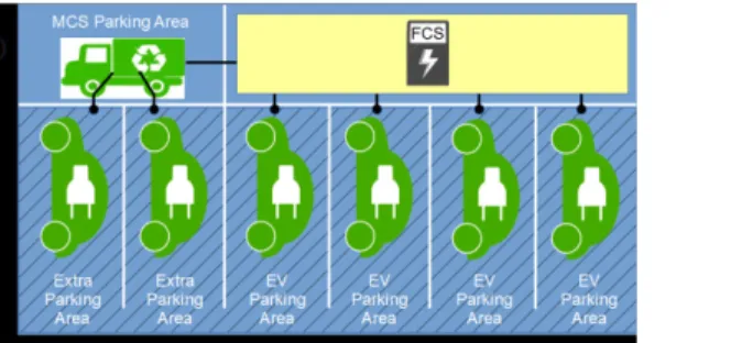
In this paper, the author classified the charging station into two type of charging station based on its mobility i.e. fixed charging station (FCS) and mobile charging station (MCS). FCS will be a fixed facility in the shape of building equipped with several CPs. The power should be gained from electricity grid or from local energy generator i.e. wind turbine or photovoltaic (PV) cell. MCS will be in the shape of electric or hybrid vehicle equipped with several CPs which can travel a distance in certain range. MCS can be stationed in the designated FCS which has extra parking area. The owner of the charging station should connect to the server of charging station (CS Server) operated by the ISO/RTO. All information about the installed CPs should be reported to the CS Server. Fig. 1(a) showed the basic schematic of a charging station which has FCS and MCS while Fig. 1(b) showed the basic client-server diagram between the EV, FCS, MCS, and the CS Server.
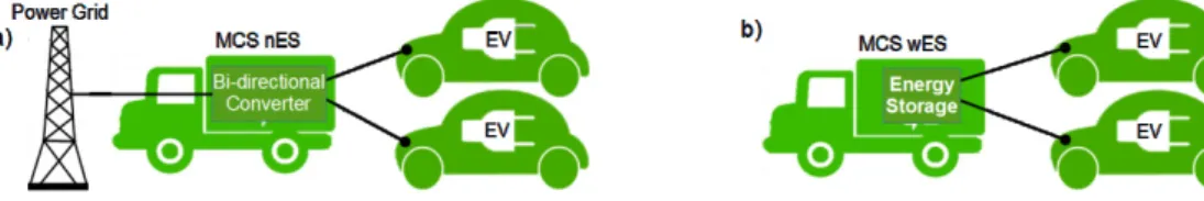
Fig. 2. MCS working mode; (a) on-grid charging mode; (b) off-grid charging mode.
3.Charging modeof the MCS
The MCS power source may come from the connection to the power grid via FCS inlet or the MCS itself can be equipped with limited energy storage [12].In this paper, the MCS unit will be categorized into two types of MCS i.e MCS with energy storage (MCS_wES) and MCS with no energy storage (MCS_nES). MCS could be dispatched in two different charging modes i.e. off-grid charging mode for MCS_wES and on-grid charging mode for MCS_nES.
When MCS_nES was stationed in certain FCS, it was connected to the power grid and charge nearby EV. In this state, MCS_nES was in on-grid charging mode because it charges the nearby EV using its connection with the power grid. When the MCS_wES was deployed to assist an emergency call from –stranded– EV outside FCS, MCS will use its energy storage and invoke off-grid charging mode because this MCS utilize its energy storage without connected to the grid. Fig. 2 describe on-grid mode and off-grid mode.
4.MCS dispatch algorithmat CS server
MCS dispatch will be an answer to two kinds of request. First is a request from overloaded FCS, and second is an emergency call from any EV located not in the FCS. The algorithm consists of six algorithms: request CS location, EV arrival/registration, request MCS, charge complete, cancel donate MCS, and cancel request MCS. The algorithm will be deployed in CS server installed in the ISO/RTO office centre. The CS server will facilitate four actors i.e. CS Server, FCS, MCS, and EV. Those algorithms will serve any command to dispatch MCS unit or any information request from the FCS or the EV. The request will be synchronised with the database of actual status and position of FCS and MCS registered on the server. This algorithm was derivatively developed from the dispatch procedure flowchart researched by S.-N. Yang et al. [12, 13].
4.1.Request CS location algorithm
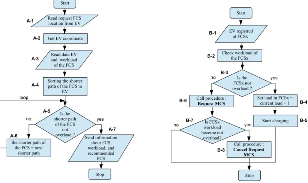
EV along the way will need the information of possible charging station as for the battery power is continuously decreasing. As one of the after sales service, the EV can access the information of the available CS using mobile application connected to the internet or global positioning system (GPS). The application can be embedded to the EV or installed on the owner’s smart phone. CS server will provide the best alternative of nearest CS using “Request CS location procedure” showed in Fig. 3.
x A-1: CS server read the request from the EV about the nearest CS and considers it as a request of a FCS.
x A-2: CS server get the coordinate of the EV requested the CS location.
x A-3: CS server read the EV location and read the location of FCSs in the database including their workload.
x A-4: CS server sort the FCS based on the shorter path of the FCS to the EV.
x A-5: CS server decides whether the nearest FCS is not overload.
x A-6: If the nearest FCS is overload, then CS server will look after the next nearest FCS. This process will be looping until CS server found FCS which is not overload.
x A-7: When CS server determined the FCS which is not overload, the location will be sent to the requesting EV. After the EV receives the FCSs information including their workload, the EV can decide manually which CS it will go after. It is considered that the EV has learned that there is possible queue if it decides to go to the overload FCS.
Fig. 3. Request CS location procedure. Fig. 4. EV arrival/registration procedure.
4.2.EV arrival/registration algorithm
When the EV arrives at the FCS, the EV should register its arrival to the FCS. When too many EVs arrive at a FCS, specifically the number of EVs in the FCS exceeds the number of CPs; an MCS will be requested to support the FCS for relieving the charging workload. CS server will analyze this EV arrival to decide to dispatch a MCS or not using “EV arrival/registration procedure” showed in Fig.4.
x B-1: When EV arrives at the FCS, EV registers its arrival to the FCS.
x B-2: CS server checks the workload of the FCS by checking the number of working and idle charging pole.
x B-3: CS server decides whether the FCS is not overload.
x B-4: If the FCS is not overload, the load in FCS will be set as current load plus one.
x B-5: CS server will consider that the FCS has start charging the new coming EV.
x B-6: If the FCS is overload, then the “request MCS procedure” will be invoked.
When the MCS is dispatched to the requested FCS, the FCS will be in the waiting time for the MCS arrival. In this waiting time, the FCS will remain in “request MCS” state. However, if somehow the workload is become not overload, such as one charging EV decided to unplug the charging process, then the FCS will need to invoke “cancel request MCS” as for the availability of its charging pole.
x B-7: CS server will monitor the workload of the FCS and decide whether it is become not overload.
x B-8: If somehow the workload become not overload, the CS server will invoke “cancel request MCS Procedure”
4.3.Request MCS algorithm
After “request MCS procedure” is invoked, MCS unit will be dispatched using “request MCS procedure” shown
in Fig. 5. Start Read request FCS location from EV Get EV coordinate Read data EV and workload of the FCS Sorting the shorter path of the FCS to EV Is the shorter path of the FCS not
overload ? Send information
about FCS, workload, and recommended
FCS the shorter path of
the FCS = next shorter path yes no loop Stop loop A-1 A-2 A-3 A-4 A-5 A-6 A-7 Start EV registred at FCSx Check workload of the FCSx Is the FCSx not overload ? Set load in FCSx = current load + 1 Start charging Call procedure : Request MCS yes no workload Is FCSx become not overload? Call procedure : Cancel Request MCS yes Stop no B-1 B-2 B-3 B-4 B-5 B-6 B-7 B-8
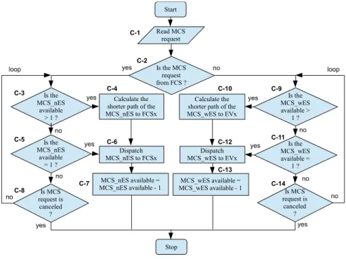
Fig. 5. Request MCS procedure for dispatching MCS_nES or MCS_wES.
The CS server will decide which type of MCS unit will be dispatched by determining where the request comes from. If the request is come from the FCS, then the dispatched unit will be MCS_nES. Otherwise, if the request is come from the EV outside FCS, then the dispatched unit will be MCS_wES. MCS_nES will provide on-grid charging while MCS_wES will undertake off-grid charging.
x C-1: CS server detects invoked “request MCS procedure”.
x C-2: CS server determines where the request comes from. Whether it comes from FCS or from EV.
If the request comes from FCS, it is considered that a FCS has surpassed its workload limit and need assistance of MCS_nES unit performing on-grid charging.
x C-3: CS server checks if the available MCS_nES is more than one unit or not.
x C-4: If there are more than one available MCS_nES, CS server calculate the path from the MCS_nESs to the FCS and decided which one is the nearest.
x C-5: CS server checks if the available MCS_nES is only one unit or not.
x C-6: If there is only one MCS_nES unit available, CS server dispatches the said MCS_nES to the requesting FCS.
x C-7: CS server set the database of available MCS_nES becomes the current MCS_nES minus one.
x C-8: If there is no available MCS_nES detected, then the system will check whether there is any cancelation or not. If the is no cancelation, then the system will be back on the C-3 and keep on looping until there is MCS_nES available. But if somehow any cancelation was invoked before the system finds available MCS_nES, then the procedure will be terminated.
If the request is not come from FCS, the request must come from EV with no FCS affiliated. It is considered that is it an emergency call from EV which is not capable to reach the nearest FCS and need assistance of MCS_wES unit performing off-grid charging.
Start Read MCS request Is the MCS request from FCS ? Is the MCS_nES available > 1 ? Calculate the shorter path of the MCS_nES to FCSx Dispatch MCS_nES to FCSx Is the MCS_nES available = 1 ? yes no yes no yes no request is Is MCS canceled ? yes no Stop loop Is the MCS_wES available > 1 ? Calculate the
shorter path of the MCS_wES to EVx Dispatch MCS_wES to EVx Is the MCS_wES available = 1 ? yes no yes no Is MCS request is canceled ? yes no loop MCS_wES available = MCS_wES available - 1 MCS_nES available = MCS_nES available - 1 C-1 C-2 C-3 C-5 C-8 C-7 C-6 C-4 C-10 C-12 C-13 C-9 C-11 C-14
x C-9: CS server checks if the available MCS_wES is more than one unit or not.
x C-10: If there are more than one available MCS_wES, CS server calculate the path from the MCS_wESs to the EV and decided which one is the nearest.
x C-11: CS server checks if the available MCS_wES is only one unit or not.
x C-12: If there is only one MCS_wES unit available, CS server dispatches the said MCS_wES to the requesting EV.
x C-13: CS server set the database of available MCS_wES becomes the current MCS_wES minus one.
x C-14: If there is no available MCS_wES detected, then the system will check whether there is any cancelation or not. If the is no cancelation, then the system will be back on the C-9 and keep on looping until there is
MCS_wES available. But if somehow any cancelation was invoked before the system finds available MCS_wES, then the procedure will be terminated.
When the system is looping in waiting for available MCS_nES or MCS_wES, the requesting FCS or EV should be
in “waiting state”. In this paper, MCS_wES cannot comply the request from FCS because MCS_wES was only
prepared for any emergency call from EV outside FCS. And vice versa, MCS_nES will not comply any request from EV outside FCS because its absence of power source. Later development may be conducted to synchronize the simultaneous dispatch of MCS_nES and MCS_wES.
When CS server dispatch MCS unit, supposedly the MCS unit successfully arrive at the requesting point. However, there are possibilities that MCS unit did not achieve its target. The first possibility is that the requesting FCS or EV has cancelled it request. It could be that there is an available charging pole had occurred so they can have charging process carried on. In this order, CS server will invoke “cancel request MCS procedure”.
Second possibility is that the MCS is having obstacle along the way to the target. The obstacles could be an internal breakdown or any external interference. Therefore, the MCS unit should report to CS server that dispatched MCS cannot complete donate process and invoke “cancel donate MCS procedure”.
4.4.Cancel request MCS algorithm
Before the MCS unit has arrived, the requesting FCS or EV may cancel the request of MCS unilaterally. When CS server gets this cancelation, CS server should invoke “cancel request MCS procedure” shown in Fig.6. After that, CS server will command the cancelled MCS unit to go to the designated destination.
x D-1: CS server read a cancelation of MCS request.
x D-2: CS server determines whether the cancelation came from FCS or EV.
If the cancelation came from the FCS, CS server’s next step will be focused on MCS_nES unit on the database.
x D-3: CS server checks whether there was any MCS_nES has been dispatched. If there is no MCS had been dispatched, the procedure will be safely terminated.
x D-4: If there was any MCS_nES had been dispatched, CS server will release the on-the-way MCS_nES unit from the responsibility to reach the requested FCS. After that, CS server will update of the number of MCS_nES available become current number plus one.
x D-5: CS server checks whether there is any other request for MCS_nES unit.
x D-6: If there is any other request on MCS_nES unit, CS server should repeat “request MCS procedure”.
x D-7: If there is no other requeston MCS_nES unit, CS server commands the MCS_nES unit to go to the nearest FCS.
If the cancelation is not come from the FCS, then it is determined that the cancelation is come from EV outside the FCS. CS server’s next step will be focused on MCS_wES unit on the database.
Fig. 6. Cancel request MCS procedure.
x D-8: CS server checks whether there was any MCS_wES has been dispatched. If there is no MCS had been dispatched, the procedure will be safely terminated.
x D-9: If there was any MCS_wES had been dispatched, CS server will release the on-the-way unit from the responsibility to reach the requested EV and updates the number of MCS_wES available become plus one.
x D-10: CS server checks whether there is any other request for MCS_wES unit.
x D-11: If there is any other request on MCS_wES unit, CS server should repeat “request MCS procedure”.
x D-12: If there is no other requeston MCS_wES unit, CS server commands the MCS_wES unit to go to the nearest FCS.
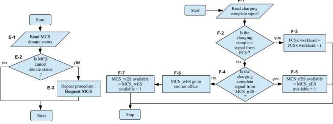
4.5.Cancel donate MCS algorithm
When there is any obstacle has occurred along the way to the MCS destination, MCS unit should report its disability to carry on the donation process. MCS unit should invoke “cancel donate MCS procedure” shown in Fig.7. After that, CS server should repeat “request MCS procedure” to cover for the disabled MCS unit.
x E-1: CS server read MCS donate status since the MCS is dispatched from the starting point until the MCS reach the requesting point
x E-2: CS server will respond to any cancel donate status given by dispatched MCS.
x E-3: If there is any cancel donate status, CS server will release the MCS from the duty and repeat “request MCS procedure” to get another available MCS.
4.6.Charge complete algorithm
The last procedure in this algorithm is that the charging process was complete. This procedure should be invoked by the FCS which just has idle charging pole or by the MCS which have its charging poles are no longer occupied. The purpose of this procedure is to update the database of available FCS and MCS in the central office. The “charge complete procedure” has shown in Fig.8.
Start Read cancel request MCS MCS_wES available = MCS_wES available + 1 Is the MCS_wES had been dispatch ? Stop Set MCS_wES to go to central office yes no Is any other request MCS_wES ? yes no Is the MCS canceled from FCS ? MCS_nES available = MCS_nES available + 1 Is the MCS_nES had been dispatch ? Set MCS_nES to go to nearest FCS yes no Is any other request MCS_nES ? yes no yes no Repeat procedure :
Request MCS Repeat procedure : Request MCS
D-1 D-2 D-3 D-4 D-5 D-6 D-7 D-8 D-9 D-10 D-12 D-11
Fig. 7. Cancel donate MCS procedure. Fig. 8. Basic procedure of MCS dispatch.
x F-1: CS server read the complete charging signal from FCS and MCS.
x F-2: CS server determines whether the signal is coming from FCS or not.
x F-3: If the signal was come from a FCS, CS server will update the database of the said FCS workload become minus one.
x F-4: If the signal was not come from FCS, it is means that the signal was come from MCS. CS server will determine whether it was coming from MCS_nES or not.
x F-5: If the signal was come from MCS_nES, CS server will update the database of available MCS_nES become plus one and command the said MCS_nES to stand by in the current FCS until any other MCS request was invoked.
x F-6: It the signal was not come from MCS_wES, it is means that the signal was come from MCS_wES. CS server will command the said MCS_wES to go back to central office
x F-7: CS server will update the database of available MCS_wES become plus one
5.Result and discussion
5.1.Improvement of dispatching MCS unit
Service improvement provided for EV owner can be seen by the waiting time. By dispatching MCS unit to the overload FCS, would reduce the waiting time for EV queuing in the FCS. Fig.9 shows the improvement of waiting time is significantly improved by the MCS network with 10% mobile CPs allocated to the MCSs[12].Fig. 9 shows not only that the deployment of MCS can reduce the waiting time of EV but also gave the best alternative number of CPs in the MCS especially when the budget is limited. For better investment, the operator can limit the number of MCS to less than 6 to save the operating costs and still have efficiency on reducing the waiting times of EVs.
When the improvement on waiting time of the EV queuing in FCS can be calculated, the improvement for EV waiting outside the FCS still hardly calculated. Beside that complexity on calculation outside the FCS, surely MCS unit shows that its primary function is highly needed especially to improve the after sales of the EVs outside the FCS cover range. Further research should be conducted to calculate the improvement received by the EV outside FCS from this dispatch algorithm.
Start Read MCS donate status Is MCS cancel donate status ? Stop Repeat procedure : Request MCS yes no E-1 E-2 E-3
Start Read charging
complete signal Is the charging complete signal from FCS ? FCSx workload = FCSx workload - 1 yes no MCS_nES available = MCS_nES available + 1 Is the charging complete signal from MCS_nES ? Stop MCS_wES go to central office MCS_wES available = MCS_wES available + 1 yes no F-1 F-2 F-3 F-5 F-4 F-6 F-7
Fig. 9. Effect of the MSC number to the improvement of waiting time [12].
Fig. 10. Information management system to support the dispatch of the MCS.
5.2.IMS support and smart grid communication
Conducting information flow from all the actors of this algorithm requires an establish network with special feature to detect the queuing with optimal coverage area. One designated information management system (IMS) was developed to facilitate the whole information flow in this system (Shown in Fig. 10). First information flow should be for EV status. The status could be send by the EV owner or by the EV itself. EV owner could send or request information using smart phone-based application. Since android operating system offers a widespread use in this past couple years, a development on android based application with friendly user interface will be a much help for EV owners–CS server communication. Another alternative is to install the application on the EV itself. The application could have been embedded within the energy management system (EMS) so the power storage status could be monitored continuously. In this EV side, installing the application either in the EV or in the owner’s smart phone should need a permission and full awareness from the EV owner. From the side of MCS and FCS, network operator could easily install the application on the MCS dashboard or in the FCS control facility. As a consideration, the application is not only providing the energy status information but also geo location information. Detail explanation for this application will not be discussed in this paper.
Escalating the coverage area will increase customer satisfaction while travel across long range. Beside local range support, global support should provide coverage area expansion on this algorithm implementation [13]. Utilizing existing terrestrial cellular network is a promising way to establish an information network. The network operator would need an agreement on a cross-region communication providing wider coverage area. Remote area should be covered by satellite communication system. It would not be a problem for FCS and MCS, but not every EV would be able to get in touch with satellite communication system. Future alternative is to make use of smart grid communication system [12]. Smart grid concept facilitates information flow on every power node in its coverage. Without installing any application on the FCS, smart grid network would be able to detect overload FCS with detecting the flow of electricity demanded. Nowadays, smart grid network is still developed in early stages of implementation, however, many industrial country such as USA and China has invested million USD on the development of smart grid technology [14].
5.3.Role in supporting V2G transition
Vehicle-to-Grid (V2G) connectivity concept was a concept to selling the electricity back to the grid [3, 15]. The PHEV would be charged at the home at the nighttime when the demand is low and then discharged the power back on the grid on the day time where the demand is high. This concept of selling back the power to the grid would need full cooperation from the ISO/RTO to operate bulk power system with the ESP. ISO/RTO should provide aggregator module interface at the FCS as the resource coordination with the CS server.
This dispatch algorithm would facilitate the transition on this V2G connectivity concept so the PHEV outside the FCS with enough power to discharge can sell the power back on the grid by requesting the MCS. The information system established for this dispatch algorithm also capable of detecting PHEV which is capable to discharge and send notification to the EV whether the EV is eager to discharge or not. This feature will be fully responsible of the ISO/RTO and facilitate by the SC Server.
6.Conclusion
Dispatch algorithm developed in this paper was designed to facilitate any MCS request from overload FCS or from EV outside FCS. The entire algorithm should be implanted to CS server installed in operator’s central office. All CS server calculation for EV, MCS, and FCS information was assisted by a database connected to global network. CS server dispatches the MCS using six algorithms: request CS location, EV arrival/registration, request MCS, cancel donate MCS, cancel request MCS and charge complete. This dispatch algorithm helps the queued EVs in full occupied FCS to improve their waiting time. This dispatch algorithm also helps EV outside FCS to get charged by the MCS. Information management system was established to support this algorithm using global internet connection. Smart grid technology would also provide an adaptive grid to facilitate a better reading for the implementation of this algorithm. This MCS dispatch algorithm also supports the operator to have an easier handle on V2G transition. This research will further assist the creation of smart city or Small Island concept.
Acknowledgements
The Authors would like to thank all researchers in research centre for electrical power and mechatronics, Indonesian Institute of Sciences for supporting the completion of this paper.
References
[1] T. J. Hammons, "Integrating renewable energy sources into European grids," International Journal of Electrical Power & Energy Systems,
vol. 30, pp. 462-475, 2008.
[2] EPRI and NRDC, "Environmental Assessment of Plug-In Hybrid Electric Vehicles. Volume 1: Nationwide Greenhouse Gas Emissions," July 2007.
[3] C. Guille and G. Gross, "A conceptual framework for the vehicle-to-grid (V2G) implementation," Energy Policy, vol. 37, pp. 4379-4390, 2009.
[4] T. G. S. Román, et al., "Regulatory framework and business models for charging plug-in electric vehicles: Infrastructure, agents, and commercial relationships," Energy Policy, vol. 39, pp. 6360–6375, October 2011.
[5] Y. M. Nie and M. Ghamami, "A corridor-centric approach to planning electric vehicle charging infrastructure," Transportation Research Part B: Methodological, vol. 57, pp. 172–190, November 2013.
[6] J. Dong, et al., "Charging infrastructure planning for promoting battery electric vehicles: An activity-based approach using multiday travel data," Transportation Research Part C: Emerging Technologies, vol. 38, pp. 44–55, January 2014.
[7] J. Yang, et al., "An improved PSO-based charging strategy of electric vehicles in electrical distribution grid," Applied Energy, vol. 128, pp. 82–92, 1 September 2014.
[8] P. Sadeghi-Barzani, et al., "Optimal fast charging station placing and sizing," Applied Energy, vol. 125, pp. 289–299, 15 July 2014. [9] S. G. Nurre, et al., "Managing operations of plug-in hybrid electric vehicle (PHEV) exchange stations for use with a smart grid," Energy
Policy, vol. 67, pp. 364–377, April 2014.
[10] L. Jian, et al., "A scenario of vehicle-to-grid implementation and its double-layer optimal charging strategy for minimizing load variance within regional smart grids," Energy Conversion and Management vol. 78, pp. 508–517, February 2014.
[11] Wired.com. (2011). ‘Quick Charge’ Trucks Will Save Your Stranded EV. Available: http://www.wired.com/images_blogs/autopia/2011/07/AAA-mobile-EV-charger.jpg
[12] S.-N. Yang, et al., "Mobile charging information management for smart grid networks," International Journal of Information Management, vol. 33 pp. 245– 251, 2013.
[13] S.-N. Yang, et al., "Charge scheduling of electric vehicles in highways," Mathematical and Computer Modelling, vol. 57, pp. 2873–2882, 2013.
[14] G. Electric. (2010). Top 10 nations for smart grid investment. Available: http://www.reliableplant.com/Read/27393/Nations-smart-grid-investment
[15] T. D. Atmaja and M. Mirdanies, "Vehicle-to-Grid Transition on Plug-in Hybrid Electric Vehicle Technology as the Support of Distributed Generation System," in Proceeding of Seminar on Engineering on Energy, Mechatronics, and Vehicular Technology, 2013, pp. 319-324.

![Fig. 9. Effect of the MSC number to the improvement of waiting time [12].](https://thumb-us.123doks.com/thumbv2/123dok_us/10135990.2914626/9.816.112.739.100.331/fig-effect-msc-number-improvement-waiting-time.webp)
