Self-Organising Load Balancing for OFDMA Cellular Networks
Lei, Xu
For additional information about this publication click this link.
http://qmro.qmul.ac.uk/xmlui/handle/123456789/11747
Information about this research object was correct at the time of download; we occasionally
make corrections to records, please therefore check the published record when citing. For
more information contact scholarlycommunications@qmul.ac.uk
1
Self-Organising Load Balancing for
OFDMA Cellular Networks
Lexi Xu
Submitted for the degree of Doctor of Philosophy
School of Electronic Engineering and Computer Science
Queen Mary, University of London
2
To my family
Declaration: I hereby declare that the work presented in this thesis is solely my work and that to the best of my knowledge the work is original except where indicated by reference to respective authors.
_____________________ Lexi Xu
3
Abstract
In this thesis, self-organising load balancing is investigated to deal with the uneven load distribution in OFDMA based cellular networks. In single-hop cellular networks, a self-organising cluster-based cooperative load balancing (CCLB) scheme is proposed to overcome the ‘virtual partner’ and the ‘aggravating load’ problems confronted in the conventional mobility load balancing schemes. Theoretical analysis and simulation results show that the proposed scheme can effectively reduce the call blocking probability, the handover failure rate, and the hot-spot cell’s load.
The proposed CCLB scheme consists of two stages: partner cell selection and traffic shifting. In the partner cell selection stage, a user-vote assisted clustering algorithm is proposed, which jointly considers the users’ channel condition and the surrounding cells’ load. This algorithm can select appropriate neighbouring cells as partners to construct the load balancing cluster, and deal with the ‘virtual partner’ problem. In the traffic shifting stage, a relative load response model (RLRM) is designed. RLRM coordinates multiple hot-spot cells’ shifting traffic towards their public partner, thus mitigating the ‘aggravating load’ problem of the public partner. Moreover, a traffic offloading optimisation algorithm is proposed to balance the hot-spot cell’s load within the load balancing cluster and to minimise its partners’ average call blocking probability.
The CCLB scheme is modified to apply in multi-hop cellular networks with relays deployed. Both fixed relay and mobile user relay scenarios are considered. For fixed relay cellular networks, a relay-level user shifting algorithm is proposed. This algorithm jointly considers users’ channel condition and spectrum usage of fixed relay, in order to reduce the handover failure rate and deal with the ‘aggravating load’ problem of fixed relay. In the mobile user relay scenario, the user relaying assisted traffic shifting algorithm is proposed to improve the link quality of shifted edge users, which brings about an increase in the achievable rate of shifted edge users and decrease in the handover failure rate.
4
Acknowledgment
I would like to express my gratitude to all those who helped me in the past three years. The first person I want to say “thank you” to is my supervisor Dr Yue Chen. She is a knowledgeable, charming, smart, beautiful and nice teacher. During my past research time, she gave me the strongest support and guidance for both my study and daily life. She gave me lots of freedom to study an area that interested me and she encouraged me on every small progress I have ever made. Her selflessness, warm-hearted to students and passion for the research is my treasure.
I would also like to express my appreciation to Dr John Schormans, Dr Kok Keong (Michael) Chai and Dr Chris Phillips for their helpful suggestions and comments on my research. Dr John Schormans gave me a lot of useful advice when I establish the simulation platform and modify my papers. Dr Michael Chai gave me lots of valuable suggestions on the researches of load balancing and OFDMA systems. Dr Chris Phillips gave me support and encouragement, boosting my confidence and helping me to finish the thesis well.
During the past two years, many of my QMUL friends and colleagues gave me lots of help both life and research. Thanks to Kejing, Dapeng, Hongyi, Xian, Adeel, Awais, Rehana, Yousef, Fei, Geng, Yifeng, Nan, Wenxuan, Di, Haibo, Kejiong, Peng, Dan, Yun, Dantong, Lifeng, Zhijing, Yansha and so many others.
Many thanks to my BUPT team, who assisted my research although they are far from me, including Prof. Yinghai Zhang, Prof. Weidong Wang, Dr Chaowei Wang, Xinlei, Shoufeng, Gaofeng, Yuan, Beng, Zhi, Juyi, Xianwei, Liping and many others.
In my research, there are so many people I should thank. The love they have given me is enormous and selfless. With my love and gratitude, I want to dedicate this report to all the people who have ever helped me.
5
Contents
Abstract ... 3 Acknowledgment... 4 List of Figures ... 7 List of Tables ... 11 List of Abbreviations ... 12 Chapter 1 Introduction ... 15 1.1 Background ... 15 1.2 Research Scope ... 16 1.3 Research Contribution ... 17 1.4 Author’s Publications ... 19 1.5 Thesis Organisation ... 20Chapter 2 Load Balancing in Cellular Networks ... 21
2.1 Basic Concept of Load Balancing ... 21
2.1.1 Load Balancing Scenario and Objectives ... 21
2.1.2 Load Balancing Process ... 22
2.2 Load Balancing in 2G GSM Networks ... 26
2.2.1 Multiple Access and Frequency Reuse ... 26
2.2.2 Load Balancing Schemes... 27
2.3 Load Balancing in 3G CDMA Networks ... 28
2.3.1 Multiple Access ... 28
2.3.2 Load Balancing Schemes... 29
2.4 Load Balancing in Single-Hop OFDMA Networks ... 30
2.4.1 OFDM/OFDMA ... 30
2.4.2 Mobility Load Balancing ... 31
2.4.3 Mobility Load Balancing Schemes Introduction ... 33
2.4.4 Problem Formulation in Conventional MLB ... 37
2.5 Load Balancing in Multiple-Hop OFDMA Networks ... 39
2.5.1 Load Balancing in Fixed Relay Cellular Networks ... 40
2.5.2 Load Balancing in Mobile Relay Cellular Networks ... 41
2.5.3 Challenges of Load Balancing in Multi-Hop Networks ... 42
2.6 Summary ... 43
Chapter 3 System Model and Simulation Platform... 44
3.1 System Model ... 44
3.1.1 Single-Hop Cellular Networks ... 44
3.1.2 User Relay Cellular Networks ... 45
3.1.3 Fixed Relay Cellular Networks ... 45
3.2 Overall Design of Simulation Platform... 46
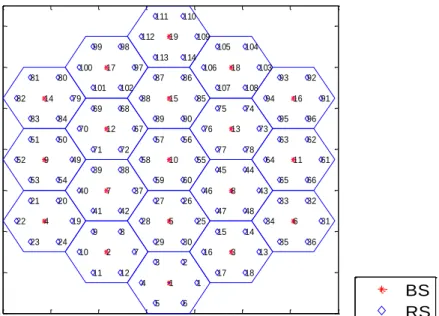
3.3 Cells Initialisation ... 48
3.3.1 Cells Initialisation in Single-Hop and User Relay Cellular Networks ... 48
3.3.2 Cells Initialisation in Fixed Relay Cellular Networks ... 50
3.4 User Distribution ... 52
3.4.1 User Distribution in Single-Hop Cellular Networks ... 52
3.4.2 User Distribution in User Relay Cellular Networks ... 53
3.4.3 User Distribution in Fixed Relay Cellular Networks ... 53
3.5 Channel Model ... 54
3.5.1 Channel Model in Single-Hop Cellular Networks ... 54
3.5.2 Channel Model in User Relay Cellular Networks ... 55
3.5.3 Channel Model in Fixed Relay Cellular Networks ... 55
6
3.7 Overall Simulation Parameters ... 58
3.7.1 Parameters in Single-Hop Cellular Networks ... 58
3.7.2 Parameters in User Relay Cellular Networks ... 59
3.7.3 Parameters in Fixed Relay Cellular Networks ... 60
3.8 Simulation Iteration ... 61
3.9 Summary ... 63
Chapter 4 Self-Organising Cluster-Based Cooperative Load Balancing ... 64
4.1 Introduction ... 64
4.2 Problem Formulation and Challenge ... 65
4.2.1 Virtual Partner Problem ... 65
4.2.2 Public Partner and Aggravating Load Problem ... 65
4.2.3 Call Blocking Probabilities Increase of Partners ... 66
4.3 Proposed CCLB scheme ... 67
4.3.1 Cluster Structure ... 68
4.3.2 Definitions and System Parameters ... 69
4.4 User-Vote assisted Clustering ... 70
4.4.1 User-Vote Model ... 71
4.4.2 Partner Selection ... 74
4.4.3 Signalling load and Complexity ... 75
4.5 Cooperative Traffic Shifting ... 77
4.5.1 Inter-Cluster Cooperation: Relative Load Response Model ... 77
4.5.2 Intra-Cluster Cooperation: Traffic Offloading Optimisation Algorithm ... 80
4.5.3 Signalling Load and Complexity ... 89
4.6 Performance Analysis ... 89
4.6.1 User-Vote Assisted Clustering ... 90
4.6.2 Cooperative Traffic Shifting ... 94
4.7 Summary ... 98
4.8 Appendix:The Analysis of η=4 in User-Vote Model ... 99
4.9 Appendix: Load Difference based Traffic Shifting ... 100
Chapter 5 Load Balancing in Multi-Hop Cellular Networks ... 102
5.1 Introduction ... 102
5.2 Cluster-Based Cooperative Load balancing in Fixed Relay Cellular Networks ... 103
5.2.1 System Model of Fixed Relay Cellular Networks ... 103
5.2.2 Problem Formulation ... 105
5.2.3 Process of CCLB Scheme ... 107
5.2.4 User-Vote assisted Clustering ... 108
5.2.5 Cell-Level Cooperative Traffic Shifting ... 112
5.2.6 Relay-Level User Shifting ... 113
5.2.7 Performance Analysis ... 117
5.3 User Relaying assisted Traffic Shifting Scheme ... 124
5.3.1 Problem Formulation ... 124
5.3.2 User Relaying Model ... 125
5.3.3 Analysis of User Relaying Model... 127
5.3.4 Proposed URTS Scheme ... 131
5.3.5 Performance Analysis ... 135
5.4 Summary ... 140
Chapter 6 Conclusions and Future Work ... 142
6.1 Specific Conclusions ... 142
6.2 Future Work ... 143
7
List of Figures
Figure 2.1 A scenario of uneven load distribution……….…21
Figure 2.2 An example of uneven load distribution among cells………..……..…23
Figure 2.3 Channel borrowing and traffic shifting based load balancing schemes……...…...25
Figure 2.4 Typical load balancing schemes for different generations of cellular networks.…26 Figure 2.5 Multiple access: FDMA and TDMA [Chen03]………...………….….26
Figure 2.6 7-cell frequency reuse technology in GSM……….………..…27
Figure 2.7 Multiple access: CDMA [Chen03]………...……...28
Figure 2.8 Power control based load balancing………..…29
Figure 2.9 OFDM subcarriers [HT09]………...30
Figure 2.10 Illustration of traffic shifting stage in MLB………...32
Figure 2.11 Illustration of HOoff adjustment in [NA07]……….….34
Figure 2.12 Illustration of HOoff adjustment process in [KAPTK10]……….……….35
Figure 2.13 Virtual partner problem………...….…37
Figure 2.14 Aggravating load problem of public partner……….………....38
Figure 2.15 Two scenarios of relay extending cell coverage……….…………..…..39
Figure 2.16 Illustration of dynamic BS-RS connection in [JBW08]………..….40
Figure 2.17 Illustration of traffic shifting in [WTJLHL10]………...………..…41
Figure 2.18 Example of load balancing via iCAR scheme in [WDQYT05]………….……....…42
Figure 2.19 RS aggravating load problem………..….43
Figure 3.1 Single-hop cellular networks……..……….………..….44
Figure 3.2 User relay cellular networks………...45
Figure 3.3 Fixed relay cellular networks………..…45
Figure 3.4 Flowchart of simulation platform………..…46
Figure 3.5 Flowchart of cell initialisation in single-hop and user relay cellular networks…..48
8
Figure 3.7 Two types of relay location……….…50
Figure 3.8 Simulated cell layouts of fixed relay cellular networks……….…....….51
Figure 3.9 Illustration of MSFR technology [GZLLZ07]………...….51
Figure 3.10 Uneven users distribution in single-hop cellular networks………….…………....52
Figure 3.11 Uneven users distribution in user relay cellular networks……….…...53
Figure 3.12 Uneven users distribution in fixed relay cellular networks……….…....53
Figure 3.13 Downlinks in three system models……….…….54
Figure 3.14 BS-RS LOS transmission [IEEE802web07]………..…....56
Figure 3.15 Sub-frame structure and PRB structure in [3GPP08a]………..57
Figure 3.16 Overall call blocking probability Vs Number of iterations (100 samples)…...62
Figure 3.17 Overall call blocking probability Vs Number of iterations (1 sample)………..…63
Figure 4.1 Problems experienced in conventional MLB……….……...65
Figure 4.2 Illustration of partners’ load increase…………...………...66
Figure 4.3 Flowchart of CCLB scheme……….67
Figure 4.4 Example of two load balancing clusters………....68
Figure 4.5 Structure and notation of load balancing clusters………...……....…69
Figure 4.6 Illustration of cluster head self-discovery……….……71
Figure 4.7 User-vote model……….…...72
Figure 4.8 Process of user-vote assisted clustering………....76
Figure 4.9 Process of cooperative traffic shifting………...77
Figure 4.10 Public partner’s load balancing spectrum analysis………...…....79
Figure 4.11 Cluster model of BSh ……….………...…….…80
Figure 4.12 Illustration of traffic offloading optimisation………...……..86
Figure 4.13 Simulation scenario for CCLB………..90
Figure 4.14 Overallcallblocking probability Vs Number of users………...……...91
Figure 4.15 Effect of cluster size on total number of shifted users………….……….…92
9
Figure 4.17 Number of HOoff adjustments comparison……….…94
Figure 4.18 Public partners’ average load comparison……….…96
Figure 4.19 Public partners’ average blocking probability comparison……….…96
Figure 4.20 Average load of cluster heads comparison……….……97
Figure 4.21 Partners’ average call blocking probability in each cluster……….….98
Figure 5.1 Layout and frequency planning in fixed relay cellular networks………..103
Figure 5.2 Virtual partner problem, aggravating load problem of public partner in fixed relay networks ………105
Figure 5.3 RS aggravating load problem……….…..106
Figure 5.4 Flowchart of CCLB scheme in fixed relay cellular networks……….…..107
Figure 5.5 Illustration of co-channel interference……….…108
Figure 5.6 Illustration of SINR report……….…...109
Figure 5.7 Flowchart of relay-level user shifting algorithm………...114
Figure 5.8 Overall process of CCLB scheme in fixed relay cellular networks……….…114
Figure 5.9 HOoff adjustments flowchart in relay-level user shifting algorithm………….…...116
Figure 5.10 Simulation scenario for CCLB in fixed relay cellular networks………....117
Figure 5.11 Overall call blocking probability comparison in clustering stage……….118
Figure 5.12 Overall call blocking probability in different cluster sizes……….119
Figure 5.13 Public partners’ average load comparison in fixed relay networks…………...120
Figure 5.14 Comparison of average load of target RSs………....121
Figure 5.15 Load balancing handover failure rate comparison in fixed relay networks...122
Figure 5.16 Illustration of handover condition in MLB………...124
Figure 5.17 User relaying model……….…126
Figure 5.18 Flowchart of URTS scheme……….…134
Figure 5.19 Simulation scenario for URTS scheme……….….135
Figure 5.20 Overall simulation flowchart of URTS scheme………..…..136
10
Figure 5.22 SINR comparison of shifted users in different SINR categories………....138 Figure 5.23 Comparison of overall rate of all shifted users………...….139 Figure 5.24 Comparison of overall rate loss of all relay users………..…………..…140
11
List of Tables
Table 3.1 Simulation parameters of single-hop cellular networks……….…………..59
Table 3.2 Simulation parameters of user relay cellular networks……….……..….60
Table 3.3 Simulation parameters of fixed relay cellular networks………..….61
Table 4.1 Cluster structure in single-hop networks simulation………...…95
Table 4.2 Public partner’s assisting cluster head in single-hop networks simulation………..95
12
List of Abbreviations
2G Second Generation 3G Third Generation 4G Fourth Generation
3GPP Third Generation Partnership Project AF Amplify-and-Forward
ARS Ad-Hoc Relaying Station BS Base Station
CBWL Channel Borrowing Without Locking CCLB Cluster-based Cooperative Load Balancing CDMA Code Division Multiple Access
DF Decode-and-Forward FDD Frequency Division Duplex
FDMA Frequency Division Multiple Access FRF Frequency Reuse Factor
GBR Guaranteed Bit Rate
GLB Geographic Load Balancing GoS Grade of Service
GSM Global System for Mobile Communication HA Hybrid Assignment
HM Handover Margin HO Handover
HOoff Cell-Specific Handover Offset
iCAR Integrated Cellular and Ad-Hoc Relay ISM Industrial, Scientific and Medical
13
KKT Karush-Kuhn-Tucker LOS Line-Of-Sight
LTE Long Term Evolution
LTE-Advanced Long Term Evolution Advanced Max-C/I Maximum Carrier to Interference Ratio MLB Mobility Load Balancing
MS Mobile Station
MSFR Modified Soft Frequency Reuse NLOS Non-Line-Of-Sight
OFDM Orthogonal Frequency Division Multiplexing OFDMA Orthogonal Frequency Division Multiple Access QoS Quality of Service
RLRM Relative Load Response Model RNC Radio Network Controller RS Relay Station
PRB Physical Resource Block RRM Radio Resource Management RS Relay Station
RSRP Reference Signal Received Power SB Simple Borrowing
SD Standard Deviation
SIR Signal to Interference Ratio
SINR Signal to Interference plus Noise Ratio SON Self-Organising Networks
TDD Time Division Duplex
TDMA Time Division Multiple Access TS Time Slot
14
TTI Transmission Time Interval
UMTS Universal Mobile Telecommunications System URTS User Relaying assisted Traffic Shifting
WCDMA Wideband Code Division Multiple Access WTS Weight of Traffic Shifting
15
Chapter 1 Introduction
1.1 Background
The fast emerging wireless services and users’ mobility may result in many users gathering in a cell, which brings large traffic demand. Thus this cell becomes heavily loaded. Meanwhile, its neighbouring cells serve a small number of users with much less traffic demand. Hence, the mobile cellular networks suffer uneven load distribution.
The uneven load distribution impacts the network performance in the following way. On one hand, due to the limited spectrum resources, the heavily loaded cell may reject access requests of new call users; due to the large traffic demand, the heavily loaded cell may be unable to provide the required quality of service (QoS) of existing users. On the other hand, its neighbouring cells may serve few users, thus these neighbouring cells are spectrum underutilised.
In order to deal with the uneven load distribution, load balancing is widely used to redistribute load among heavily loaded cell and neighbouring cells. During the load balancing process, a heavily loaded cell can select less-loaded neighbouring cells as its partner cells to shift traffic or share spectrum resources. Load balancing can reduce the load of heavily loaded cell, thus the cell allows new call users’ admission requests and is able to provide existing users with the required QoS. Therefore, load balancing can effectively improve the network performance in terms of call blocking probability, QoS and spectrum utilisation.
16
In 3GPP Long Term Evolution (LTE) / LTE-Advanced, mobility load balancing (MLB) is an effective method to address uneven load distribution [3GPP11b]. The basic idea of MLB is that a heavily loaded cell selects its partners and adjusts cell-specific handover offset towards partners, which enlarges the hard handover area [3GPP12]. Then some users in the heavily loaded cell are handed over to those partners. However, there are some problems in the conventional MLB schemes.
In conventional MLB schemes, neighbouring cell’s load has been widely used as a criterion for partner selection. This may result in the virtual partner problem, which denotes a lightly loaded neighbouring cell, while it is far from the heavily loaded cell’s edge users. After partner selection, multiple heavily loaded cells may shift traffic to a public partner. Without the coordination of multiple cells, conventional MLB schemes may result in the public partner’s aggravating load problem, which denotes the public partner becomes heavily loaded after traffic shifting. In addition, the shifted user may suffer the link quality degradation problem, since it may receive the reduced signal power from the partner cell. Relay station (RS) can extend cell coverage and enhance users’ performance in cell edge area. Therefore, RS is considered as an important technology in LTE-Advanced [3GPP10d]. Since most shifted users are served by RSs in fixed relay cellular networks, conventional MLB schemes may result in the RS aggravating load problem, which denotes the RS becomes heavily loaded after traffic shifting.
The research in this thesis aims at providing a self-organising load balancing algorithm, which can deal with above problems and provide better performance compared with conventional MLB schemes, e.g., lower call blocking probability, lower handover failure rate.
1.2 Research Scope
This thesis describes the research on the self-organising load balancing in Orthogonal Frequency Division Multiple Access (OFDMA) cellular networks. The self-organising load balancing is based on handover and requires some in-depth research considerations:
How to identify a heavily loaded cell under time-varying load; How does a heavily loaded cell select its partner cells under dynamic user distribution;
17
multiple cells shifting traffic to one partner (called the public partner);
Howtoautomatically adjustMLBparameters,e.g.,cell-specifichandover offset;
How to shift traffic in fixed relay cellular networks;
How to overcome the link qualitydegradation for shifted users.
In single-hop cellular networks, a self-organising cluster-based cooperative load balancing (CCLB) scheme is proposed. The CCLB scheme is modified to apply in fixed relay cellular networks. Furthermore, this thesis investigates how to employ non-active users as mobile relay to forward the transmission data to shifted users.
1.3 Research Contribution
The major contribution of the research work is a self-organising cluster-based cooperative load balancing (CCLB) scheme. The CCLB scheme can deal with the problems confronted in conventional MLB, including virtual partner problem, aggravating load problem of public partner, aggravating load problem of RS, and the link quality degradation of shifted user.
1. CCLB scheme in single-hop cellular networks
In single-hop cellular networks, the CCLB scheme consists of two stages: partner selection and traffic shifting. In the partner selection stage, a user-voteassistedclustering algorithm is proposed. Based on users’ channel condition and neighbouring cells’ load, the cluster head (which denotes a heavily loaded cell) selects appropriate neighbouring cells as partners, in order to construct load balancing cluster for traffic shifting. This clustering algorithm can deal with the virtual partner problem and select suitable partners.
In the traffic shifting stage, a cell-level cooperative traffic shifting algorithm is designed. In this algorithm, the cluster head effectively shifts traffic with the cooperation of partners. This algorithm includes two steps:
In the inter-cluster cooperation step, a relative load response model (RLRM) is proposed, which coordinates multiple cluster heads’ traffic shifting requests to one public partner. RLRM can address the aggravating load problem of public partners.
18
In the intra-cluster cooperation step, a traffic offloading optimisation algorithm is designed via Lagrange multipliers method. This proposed algorithm can shift the cluster head’s traffic and also minimise its partners’ average call blocking probability.2. CCLB scheme in fixed relay cellular networks
The proposed CCLB scheme is modified to apply in fixed relay cellular networks. The CCLB scheme is composed of three algorithms: user-voteassistedclustering algorithm, cell-level cooperative traffic shifting algorithm, relay-level user shifting algorithm.
The user-voteassisted clustering algorithm and the cell-level cooperative traffic shifting algorithm are modified according to the features of load balancing in fixed relay cellular networks. The modified algorithms can effectively select partners and address the aggravating load problem of public partner in fixed relay cellular networks.
After the above two stages, a novel relay-level user shifting algorithm is proposed for fixed relay cellular networks. This algorithm considers users’ channel condition and analyses the spectrum resources usage of RSs, in order to shift appropriate users from the cluster head to the partner’s RSs. This algorithm can reduce the handover failure rate and deal with the aggravating load problem of RS.
3. User relaying assisted traffic shifting
User relaying assisted traffic shifting (URTS) algorithm is the extension of CCLB scheme. The URTS algorithm works on the stage when the cluster head shifts edge user to partner cells.
Compared with the signal power from the cluster head, the shifted user receives lower signal power from the partner cell, and hence the shifted user may suffer the link quality degradation. This thesis considers a user relaying model: a non-active user is employed as a mobile relay to forward signal for a shifted user. Based on this model, a URTS algorithm is designed. This algorithm can select suitable relay user to effectively enhance the shifted user’s link quality, and keep low cost of the relay user’s energy consumption.
From the introduction above, the proposed CCLB scheme is self-organising. The user-vote assisted clustering algorithm is via cell to cell communication and is adaptive to the
19
varying channel condition and load distribution. In the cell-level cooperative traffic shifting algorithm, the cluster head and partners self-optimised offload traffic within the load balancing cluster, which is also an essential feature of self-organising networks [E308].
1.4 Author’s Publications
[Xu-1] Lexi Xu, Yue Chen, “Priority-based Resource Allocation to Guarantee Handover and Mitigate Interference for OFDMA Systems,” IEEE PIMRC2009, 13-19 September 2009, Tokyo, Japan, pp. 783-787
[Xu-2] Lexi Xu, Yue Chen, Yue Gao, “Self-organizing Load Balancing for Relay Based Cellular Networks,” IEEE CIT2010 Workshop, 29 June - 1 July 2010, Bradford, UK, pp. 791-796
[Xu-3] Lexi Xu, Yue Chen, John Schormans, Laurie Cuthbert, Tiankui Zhang, “User-Vote Assisted Self-organizing Load Balancing for OFDMA Cellular Systems,” IEEE PIMRC2011, 11-14 September 2011, Toronto, Canada, pp. 217-221
[Xu-4] Lexi Xu, Yue Chen, Yue Gao, Laurie Cuthbert, “A Self-optimizing Load Balancing Scheme for Fixed Relay Cellular Networks,” IET ICCTA2011, 12-14 October 2011, Beijing, China, pp. 306-311
[Xu-5] Lexi Xu, Yue Chen, Kok Keong Chai, Tiankui Zhang, John Schormans, Laurie Cuthbert,“Cooperative Load Balancing for OFDMA Cellular Networks,” European Wireless, 17-20 April 2012, Poznan, Poland, pp. 1-7
[Xu-6] Lexi Xu, Yue Chen, Kok Keong Chai, John Schormans, Laurie Cuthbert, “Self-Organising Cluster-based Cooperative Load Balancing in OFDMA Cellular Networks,” Wiley Wireless Communications and Mobile Computing (under minor revision)
[Xu-7] Lexi Xu, Yue Chen, KoK Keong Chai, Dantong Liu, Shaoshi Yang, John Schormans, “User Relay assisted Traffic Shifting in LTE-Advanced Systems,” IEEE VTC-Spring 2013, 2-5 June 2013, Dresden, Germany (accepted)
20
1.5 Thesis Organisation
The rest of this thesis is organised as follows.
Chapter 2 introduces the background, including the basic concept of load balancing, and the evolution of load balancing schemes from 2G networks to LTE-Advanced networks. Then this chapter discusses MLB, including its basic idea, conventional MLB schemes, and problems faced by conventional MLB schemes. Finally, load balancing in multi-hop OFDMA cellular networks is discussed.
Chapter 3 discusses the system model and simulation platform. The simulation platform consists of three system models, including single-hop cellular networks, user relay based two-hop cellular networks, and fixed relay based two-hop cellular networks. The flowchart and key modules in this simulation platform are also introduced.
Chapter 4 begins with the problem formulation of conventional MLB schemes in single-hop OFDMA cellular networks. Then a CCLB scheme is proposed to address these problems. Specifically, a user-vote assisted clustering algorithm is designed for effective partner selection. A relative load response model is designed to address the aggravating load problem of public partner. Furthermore, the traffic offloading optimisation is proposed to minimisepartners’averageblockingprobability.TheCCLBschemeisevaluated by simulation. Chapter 5 researches the load balancing in multi-hop networks, including fixed relay cellular networks and mobile relay cellular networks. In Section 5.2, CCLB scheme is applied in fixed relay cellular networks. The user-vote assisted clustering algorithm and the cell-level cooperative traffic shifting algorithm are modified to select partners and to mitigate the public partner’s aggravating load problem. Then, a novel relay-level user shifting algorithm is proposed to deal with the RS aggravating load problem. In Section 5.3, due to load balancing, shifted user’s link quality degradation problem is discussed. Then, a novel user relaying assisted traffic shifting algorithm is designed to enhance the shifted user’s link quality.
21
Chapter 2 Load Balancing in Cellular Networks
2.1 Basic Concept of Load Balancing
2.1.1 Load Balancing Scenario and Objectives
Due to the random distribution of users and the exponentially growing demand for wireless data services, mobile cellular networks face the challenges brought by the uneven load distribution. Figure 2.1 exemplifies a scenario of uneven load distribution.
Cell 4 Cell 5 Cell 6 Cell 1 (City Park) Cell 3 Cell 2 Cell 7
22
As shown in Figure 2.1, BS1 of Cell1 is located in the city park, and surrounded by six
neighbouring cells. The networks operator sets BSs coverage and pre-allocates spectrum resources according to their usual traffic load, which are estimated based on population density. Under a social event, e.g., Christmas party, music concert, thousands of users gather in the city park. The traffic generated by these users is near or even higher than the capacity of BS1. Thus Cell1 becomes heavily loaded. Meanwhile, the traffic generated by users in
neighbouring cells is very low. Therefore, the cellular networks suffer an uneven load distribution.
The impact of the uneven load distribution is reflected in different aspects. The heavily loaded cell, e.g., Cell1 in the given scenario, may reject access requests of new call users; Cell1
may not be able to provide serving users with their required QoS [KGSABS09]; the spectrum of neighbouring lighted loaded cells, such as Cell6and Cell7, are underutilised.
Load balancing is one of radio resource management functionalities. Load balancing can mitigate the negative impact of the uneven load distribution, and improve the networks performance. Commonly used performance indicators for evaluating a load balancing scheme are:
Call blocking probability
Handover failure rate (for traffic shifting based load balancing schemes)
Load reduction in heavily loaded cell
2.1.2 Load Balancing Process
The general process of load balancing includes three steps. The network controller, e.g., mobile switching center in 2G networks, identifies a hot-spot cell according to the cell’s load condition. Then, the hot-spot cell selects less-loaded neighbouring cells as its partners. After the partner selection, the hot-spot cell takes a specific load balancing scheme to balance load with partners, e.g., borrowing idle channels from partners or shifting users at the cell edge to its partners. Figure 2.2 gives an example of uneven load distribution.
23 Cell 1 Cell 6 Cell 3 Cell 7 Cell2 Cell 4 Cell 5
(a) Users distribution (b) Load of each cell Cell1
0% 100%
Cell2 Cell3 Cell4 Cell5 Cell6 Cell7
Figure 2.2 An example of uneven load distribution among cells
1)
Load Indicator
Load estimation is an essential step for load balancing schemes. In this thesis, the cell load is formulated as [3GPP10b]
Number of carriers used in the cell
Cell Load: L =
Total number of carriers available to the cell
(2.1)According to (2.1), a cell’s load is in the range from 0% to 100% (0% L 100%). In this
thesis, any cell’s load can be divided into different levels:
Overload: The traffic generated by users is equal to or larger than the cell capacity. Namely, all carriers are used in the cell.
Heavy load: A large number of carriers are used in the cell. Namely,
100%
L
L
HL.LHL is the threshold to identify a heavily loaded cell. In this thesis, the value of LHL is
70% [SOCRATES10].
Light load: A small number of carriers are used in the cell. Namely,
L
L
HL.Note that Equation (2.1) is an example of calculation cell’s load [3GPP10b]. The formula to calculate cell’s load is based on the specific multiple access technology and the load balancing scheme. In addition, different load balancing schemes may have different
24
methods or values of threshold to identify cell’s load level.
Load balancing can be triggered when the load of a cell is equal to or higher than the heavily loaded threshold LHL. In this thesis, a cell with a load above LHL is defined as a hot-spot cell.
For example, in Figure 2.2, Cell1 is a hot-spot cell and triggers load balancing.
2)
Partner Selection
The second step of balancing Cell1 load is to select one or more neighbouring cells (e.g., Cell2, Cell3…Cell7 in Figure 2.2) as the partners, which are also called as target cells or selected
neighbouring cells in some conventional load balancing schemes. If Cell1 selects an
inappropriate neighbouring cell as its partner, such as Cell5, Cell5 may become heavily
loaded after load balancing. Then, both hot-spot Cell1 and partner Cell5 will suffer high load
balancing handover failure rate and high call blocking probability. In many conventional load balancing schemes, such as [ZY89] [TY03] [NA07] [KAPTK10] [WTJLHL10] [YLCW12], this step is based on neighbouring cell’s load.
3) Channel Borrowing or Traffic Shifting
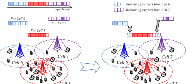
After selecting partner/s, the hot-spot cell employs a specific load balancing scheme to balance the load between the hot-spot cell and selected partners. In general, conventional load balancing schemes can be divided into two categories: channel borrowing schemes shown in Figure 2.3(a), and traffic shifting schemes shown in Figure 2.3(b).
The basic idea of channel borrowing schemes is that the hot-spot cell borrows idle spectrum from partner cells. Channel borrowing schemes are suitable for cellular networks with frequency reuse factor (FRF) greater than 1, where neighbouring cells use different frequency spectrum to mitigate inter-cell interference. As shown in Figure 2.3(a), Cell1,Cell6
and Cell7 use non-overlapping spectrum to serve users in their coverage. When Cell1 is
heavily loaded, Cell1 can borrow idle carriers from Cell6 and Cell7 to increase the available
carriers. Then Cell1 can serve more new call users and provide better QoS for existing users.
Cellular networks with FRF>1 can effectively mitigate inter-cell interference. However, the networks with FRF>1 has lower overall spectrum efficiency than networks that employ the full frequency reuse (FRF=1), where different cells use the overlapping spectrum [RY10]. In this type of networks, load balancing is based on traffic shifting:the hot-spot cell shifts edge
25
users to its partner cells via handover (a user is defined as cell edge user if the user’s reference signal received power (RSRP) difference between two neighbouring cells is lower than a threshold, e.g., 3dB [FSCK10] [SKMNT10]). Figure 2.3(b) shows a cellular network with FRF=1, where Cell1, Cell6 and Cell7 use the identical spectrum bandwidth. When Cell1
becomes a hot-spot, it shifts some of edge users to Cell6 and Cell7. This reduces the number of
users served by Cell1. The released carriers/spectrum from the shifted users can be allocated
to new call users or exiting users in Cell1.
Spectrum Cell 1 Cell 6 Cell 7 Cell 1 Cell 6 Cell 7 For Cell 1 For Cell 6 For Cell 7
Borrowing carriers from Cell 7 Borrowing carriers from Cell 6
Carrier allocation before channel borrowing Carrier allocation after channel borrowing
(a) Channel borrowing based load balancing
Cell 1 Cell 6 Cell 7 Cell 1 Cell 6 Cell 7 Shifted user
User and serving cell before traffic shifting User and serving cell after traffic shifting
For Cell 1 For Cell 6 For Cell 7 Spectrum For Cell 1 For Cell 6 For Cell 7 Spectrum
(b) Traffic shifting based load balancing
Figure 2.3 Channel borrowing and traffic shifting based load balancing schemes
In the past two decades, load balancing has been investigated in both academia and industry. The specific load balancing scheme is related to specific multiple access technology and
26
frequency reuse technology in cellular networks. Figure 2.4 illustrates the widely used load balancing schemes from the 2G to the future LTE/LTE-Advanced cellular networks.
2G GSM
FDMA/TDMA
3G
CDMA
LTE/LTE-Advanced
OFDMA
Channel borrowing Power control based load balancing
Geographic load balancing
Single-hop: Mobility load balancing Multi-hop: Relay to shift traffic
Figure 2.4 Typical load balancing schemes for different generations of cellular networks
2.2 Load Balancing in 2G GSM Networks
2.2.1 Multiple Access and Frequency Reuse
Figure 2.5 Multiple access: FDMA and TDMA [Chen03]
Figure 2.5 shows the two multiple access technologies used in Global System for Mobile Communication (GSM) networks. In Frequency Division Multiple Access (FDMA), signals for different users are transmitted in different frequency bands at the same time. In Time Division Multiple Access (TDMA), signals for different users are transmitted in the same frequency band at different times [Chen03].
GSM networks jointly employ FDMA and TDMA. In FDMA, the network operator divides the whole spectrum into several carriers, and each carrier has a unique frequency. In TDMA, each carrier is divided into eight time slots. Therefore, users transmit their signals at different time slots of different carriers.
If neighbouring cells assign the same time slot of co-channel carriers to their users, these users will suffer severe co-channel interference. In order to deal with this problem, GSM
27
network operators employ the frequency reuse technology to segregate co-channel carriers in neighbouring cells. Figure 2.6 shows the typical 7-cell frequency reuse technology (FRF=7). The cellular networks consist of three clusters, and each cluster includes 7 cells. The total carriers are divided into 7 groups of carriers, as groupA, B, C, D, E, F, G, respectively. In a cluster, each cell is pre-allocated one corresponding group of carriers. In order to mitigate co-channel interference, a group of carriers can be reused in neighbouring clusters’ cells, if the distance is longer than the minimum frequency reuse distance.
group A Cell1 group B Cell2 group C Cell3 group D Cell4 group E Cell5 group F Cell6 group G Cell7 group A Cell8 group B Cell9 group C Cell10 group D Cell11 group E Cell12 group F Cell13 group G Cell14 group A Cell15 group B Cell16 group C Cell17 group D Cell18 group E Cell19 group F Cell20 group G Cell21 Minimum frequency reuse distance
7-cell
cluster
group of carriers Cell number Spectrumgroup A group B group C group D group E group F group G
Figure 2.6 7-cell frequency reuse technology in GSM
2.2.2 Load Balancing Schemes
Channel borrowing is a popular load balancing method in GSM networks [EP73] [JR93a] [JR93b]. The basic idea is that the hot-spot cell borrows idle carriers from intra-cluster neighbouring cells. For example, in Figure 2.6, it is assumed that Cell1 is a hot-spot and uses
all carriers in group A, while Cell6and Cell7 are lightly loaded. Then Cell1 borrows part of idle
carriers from intra-cluster neighbouring cells, including idle carriers in group F from Cell6,
and idle carriers in group G from Cell7.
28
Simple borrowing scheme (SB): A hot-spot cell borrows the idle carriers from intra-cluster neighbouring cells, and the channel locking mechanism is used [ZY89].
Channel locking mechanism: This mechanism aims at reducing the co-channel interference resulting from carriers borrowing. Hence, when the hot-spot cell borrows a carrier, neighbouring clusters’ cells within the minimum frequency reuse distance cannot use this carrier [JR94]. For example, in Figure 2.6, if Cell1 borrows a carrier (in group F)
from Cell6, neighbouring clusters’ Cell13 and Cell20 cannot use this carrier (in group F) as
well. This is because that the co-channel distance of Cell1-to-Cell13 and that of Cell1 -to-Cell20 are shorter than the minimum frequency reuse distance.
Hybrid assignment scheme (HA): HA is also based on channel borrowing [KG78] [ZY89]. In HA, each cell divides its carriers into two subsets: one subset carriers can only be used by the original cell; while the other subset carriers can be borrowed under the channel locking mechanism, in order to mitigate the co-channel interference [ZY89].
Channel borrowing without locking scheme (CBWL): Because the channel locking mechanism mitigates the co-channel interference with the expense of the low spectrum utilisation of neighbouring clusters, CBWL is designed in [JR93b] [JR94]. In CBWL, the spot cell allocates the borrowed carriers to users in cell inner area. Then, the hot-spot cell transmits signals to these users with reduced transmit power. Thus, the co-channel interference yielded by carriers borrowing is slightly heavier, compared with that in SB/HA. Therefore, channel locking mechanism is not necessary in CBWL, and the co-channel carriers can also be used by cells in neighbouring clusters [JR94]. CBWL can achieve a more effective spectrum utilisation than SB and HA.
2.3 Load Balancing in 3G CDMA Networks
2.3.1 Multiple Access
29
3G standards (UMTS, cdma2000) employ wideband Code Division Multiple Access (CDMA) technology as shown in Figure 2.7. Signals for different users are identified via spreading code in spread-spectrum [Goldsmith05]. In a cell, users transmit signals in the same frequency band at the same time. Therefore, a user’s signal acts as the interference to other users [NADN06]. Load balancing can improve CDMA networks performance through reducing the number of users in the hot-spot cell, thus mitigating the intra-cell interference.
2.3.2 Load Balancing Schemes
In 3G CDMA networks, all cells use the same spectrum. This leaves little space for channel borrowing. Therefore, load balancing takes a different approach: the hot-spot cell shifts some of serving traffic to less-loaded neighbouring cells [NPPDBC03] [WZ05] [NADN06] [Yao07]. In this thesis, two types of load balancing in CDMA networks are discussed, including power control based load balancing scheme and geographic load balancing scheme.
1)
Power Control based Load Balancing
Figure 2.8 illustrates the basic idea of the power control based load balancing scheme in WCDMA networks. The hot-spot BS1 reduces its channel transmit power or rejects edge
users’ requests of increasing transmit power [WZ05]. These mechanisms could shift some users to the lightly loaded BS2. The reduced number of users in Cell1 could improve the SIR
(signal to interference ratio) of Cell1’s serving users.
Before BS2 light load BS1 hot-spot After BS2 light load BS1 hot-spot
Figure 2.8 Power control based load balancing
2)
Geographic Load Balancing
In previous research at Queen Mary University of London, geographic load balancing (GLB) is researched in [NPPDBC03] [Yao07]. The pre-condition of GLB is that each BS equips smart
30
antennas. Smart antennas employ smart signal processing algorithms to identify the signal direction of arrival, and then track the antenna beam of the target user dynamically [Yao07]. More specifically, the radio network controller (RNC) collects the users’ location information in order to know the time-varying traffic distribution in cellular networks. Then, RNC uses sophisticated computation, such as genetic algorithm, to optimise each cell’s coverage. Finally, RNC adjusts the smart antennas’ pattern. In this way, GLB intelligently changes the cellular coverage according to the time-varying geographic traffic distribution.
Compared with the power control based load balancing scheme, GLB can adjust cell coverage more accurately. This is because that the sophisticated computation can adjust smart antenna pattern precisely, thus achieving good traffic distribution in cellular networks. The limitation of GLB is that BSs need to be equipped with smart antennas, which are more expensive than the ordinary three-sector antennas.
2.4 Load Balancing in Single-Hop OFDMA Networks
Compared with 3G networks, 4G networks, such as 3GPP LTE/LTE-Advanced networks, put forward higher data rate requirements of services. The CDMA technique becomes the bottle-neck for developing higher-speed mobile networks. Due to the high spectrum efficiency of Orthogonal Frequency Division Multiplexing (OFDM), LTE/LTE-Advanced networks employ Orthogonal Frequency Division Multiple Access (OFDMA) as the multiple access technology.
2.4.1 OFDM/OFDMA
31
The basic idea of an OFDM system is to use narrow, mutually orthogonal subcarriers to carry data. As shown in Figure 2.9 (Figure 4.4 in [HT09]), OFDM divides the high rate data stream into several parallel, low rate data streams. Each low rate data stream is assigned to one subcarrier for transmission. At the sampling instant of a single subcarrier, the other subcarriers have a zero value. Therefore, thesubcarriers are orthogonal.
OFDMA is a multiple access method of the OFDM technology. OFDMA is achieved by assigning different subcarriers to different users.
The OFDM/OFDMA brings following benefits for cellular networks:
High spectral efficiency: A cell allocates different subcarriers to different users. Due to the orthogonality of subcarriers, the intra-cell interference is mitigated significantly. Therefore, OFDMA system can achieve a high rate [Xiao10].
Anti-fading: OFDMA system can effectively combat frequency-selective fading. It is due to the fact that OFDM divides the wideband transmission into narrowband transmission on several subcarriers, each subcarrier can be employed as a flat fading channel [HT09].
Flexible resource allocation: OFDMA system can select certain subcarriers for transmission according to the channel condition, thus achieving flexible resource allocation; OFDMA system can also fully make use of frequency diversity and multi-user diversity to achieve good system performance [HT09] [Xiao10].
2.4.2 Mobility Load Balancing
In order to achieve high cell capacity, one of frequency reuse technologies considered in LTE/LTE-Advanced networks is that all cells share the same spectrum (FRF=1) [3GPP10c] [RY10]. Channel borrowing based load balancing schemes, which are widely used in 2G GSM networks, are not widely used in these networks.
In OFDMA based LTE/LTE-Advanced cellular networks, the intra-cell interference is negligible due to the orthogonality of subcarriers. Besides, LTE/LTE-Advanced networks are distributed control. Power control based load balancing schemes may bring the problems of coverage hole and signalling overhead in distributed control networks. Therefore, power control based load balancing schemes, which are used in 3G CDMA networks, are not widely used in OFDMA based LTE/LTE-Advanced networks.
32
In order to effectively balance the load in LTE/LTE-Advanced networks, 3GPP release-8 defines mobility load balancing (MLB) as a SON1 (self-organising networks) functionality
[3GPP08b]. MLB aims at shifting the traffic load from a hot-spot cell to less-loaded neighbouring cells, via adjustingthe cell-specific handover offset(HOoff)to enforce handover.
Generally, MLB is composed of two stages: partner selection and traffic shifting. In the partner selection stage, the hot-spot cell selects less-loaded neighbouring cells as partners, which are also called as target cells or selected neighbouring cells in some MLB schemes. This stage in many conventional MLB schemes is based on neighbouring cell’s load. In the traffic shifting stage, the hot-spot cell calculates the amount of shifting traffic and adjusts
HOoff towards each partner. The adjusted HOoff enlarges the handover area, thus shifting cell
edge users to selected partner cells. The traffic shifting stage is illustrated in Figure 2.10, where Cell1 is a hot-spot and intends to offload traffic to partner Cell2. However, the user’s RSRP2 from BS2 is weaker than RSRP1 from BS1, and hencethe edge user is unable to trigger
handover. In order to shift this edge user, BS1 adjusts its HOoff towards BS2. Once the hard
handover condition (Event A3 in [3GPP12]), which is shown in (2.2), is meet, the user will be handed over to BS2. BS2 edge user edge user BS1 BS1
(a) Cell region
RSRP2
RSRP1
RSRP: reference signal received power
HOoff (1,2)- HOhys R SR P (d B ) BS2 (b) RSRP comparison RSRP2 Trigger handover in MLB Distance BS1 Original handover point
RSRP2+HOoff (1,2)> RSRP1+HOhys
RSRP1
Figure 2.10 Illustration of traffic shifting stage in MLB
33
HOoff (1, 2) + RSRP2 > RSRP1 + HOhys (2.2)
where HOhysis the handover hysteresis, HOhys is fixed and HOhys=2dB [LGK10].
HOhys can ensure that HOoff(1,2)+RSRP2 is 2dB higher than RSRP1,in order to deal withthe
ping-pong handover.The ping-pong handover denotes that the user is handed over to Cell2
and then it is handed over back to Cell1 [JBTMK10].
2.4.3 Mobility Load Balancing Schemes Introduction
In recent years, MLB has drawn a lot of attention from both industry and academia. This section introduces the conventional MLB schemes in [NA07] [KAPTK10] [LLZL10] [LSJB10] [ZQMZ10a].
2.4.3.1 Handover Adaptation for MLB
Among early research of MLB, the contribution of Ridha Nasri andZwi Altman in [NA07] is the milestone. Ridha Nasri et al. proposed a general principle of cell-specific handover offset (HOoff) adjustments ([NA07] employed handover margin (HM) in the handover condition
determination, instead of HOoff. Assuming HOoff (i,j) is the handover offset from Celli to Cellj,
and HM(i,j) is the handover margin from Celli to Cellj, their values follow
( , )
1
( , )
HO i j
HM i j
. In order to keep consistence in this thesis, Section 2.4.3.1 uses HOoff, which is in employed by 3GPP [3GPP12], to introduce the general principle).In [NA07],the hot-spot cell chooses all lightly loaded neighbouring cells as its partners, via comparing cells load. Since the traffic direction is from a hot-spot cell to each partner, based on the load difference between Celli and Cellj, the hot-spot Celli adjusts HOoff (i,j) to partner Cellj via the HOoff (i,j) adjustment function
f L L
( ,
i j)
in (2.3).( , )
( ,
)
off i j
HO
i j
f L L
(2.3) where Li and Lj are the load of Celli and Cellj, respectively.
0%
L L
i,
j
100%
.L
i
L
j isthe load difference between Celli and Cellj, and
1
L
i
L
j
1
.34
( ,
i j)
f L L
shouldsatisfy the following general principle:(a)
f L L
( ,
i j)
is an increasing function ofL
i
L
j, under
1
L
iL
j1
.When LiLj 1,the value of
f L L
( ,
i j)
equals the minimum handover offset minoff
HO
. When Li Lj 1,the value of
f L L
( ,
i j)
equals the maximum handover offsetHO
offmax.(b)
f L L
( ,
i j)
f L L
( , )
j i
f
(0)
.where
f L L
( ,
i j)
is the HOoff(i,j) adjustment function from Celli to Cellj,f L L
( , )
j i is theHOoff(j,i) adjustment function from Celljto Celli. f(0) is the value of the planned handover
offset when the uniformity of cell loads (LiLj 0) are reached [NA07].
To our knowledge, a typical value of f(0) is 0, and the minimum handover offset
min max
off off
HO
HO
. Then, we illustrate the general principle in Figure 2.11. (a) keeps the value of HOoff(i,j) is in the range fromHO
offmin tomax
off
HO
. (b) is to mitigate a shifted user(fromCellito Cellj) handing over back to the hot-spot cell (from Celljto Celli).
Cell j
Partner Hot-spot Cell i
f(0)
HOoff(i,j) range max off HO min max (HOoff HOoff ) min off HO min ( , ) (0) ( , ) 100%, 0% ( , ) 0%, 100% off i j max off off i j off off i j HO i j f L L HO i j HO L L HO i j HO L L Figure 2.11 Illustration of HOoff adjustment in [NA07]
2.4.3.2 Precise HO
offadjustment based MLB
In order to precisely shift traffic to balance load among cells, based on the general principle of HOoffadjustment in[NA07], Raymond Kwan et al. researched the precise HOoff adjustments
35
In [KAPTK10], a hot-spot cell selects all lightly loaded neighbouring cells, whose load are
th
lower than the hot-spot cell’s load, as its partners. Then, the hot-spot Celli preciselyadjusts HOoff(i,j) towards Cellj, in order to equalise the load between the two cells. The HOoff(i,j) adjustment process is illustrated in Figure 2.12. Celligradually adjusts HOoff(i,j) with
the offset step size ζ (HOoff(i,j)←HOoff(i,j)+ζ, and ζ=0.5dB), until the two cells’ load difference
meet the requirement of traffic shifting in [KAPTK10].
Similarly, Weihao Lv et al. [LLZL10] also designed a precise HOoff adjustment based MLB
scheme.
HOoff (i,j) ← HOoff (i,j)+ζ
Load difference between two cells reaches the requirement
Exit N Y Y N Begin Handover determination Load measurement
?
min maxoff off off
HO < HO (i, j) < HO
Load measurement
Figure 2.12 Illustration of HOoff adjustment process in [KAPTK10]
2.4.3.3 Load Increment Estimation based MLB
The preceding MLB schemes, such as [NA07], [KAPTK10] and [LLZL10], mainly consider the load reduction of the hot-spot cell. Due to the limited spectrum resources of the partner, the partner may have no capability to serve all shifted users and even reject the handover requests.
36
MLB scheme. After partner selection (partner cell is called target eNB in [LSJB10]), the hot-spot cell estimates each partner cell’s load increment, which is resulted from the possible shifted edge users. Based on the estimated load increment, in the traffic shifting stage, the hot-spot cell tries to shift traffic and to keep each partner’s load no exceed the load reported as available by the partner [LSJB10]. This scheme can reduce handover failure rate and improve user’s satisfaction after shifting.
2.4.3.4 BS state analysis based MLB
As investigated in [HZZYW10] [JBTMK10], the handover procedure introduced by MLB consumes system signalling load and may impact networks performance in terms of handover failure and ping-pong handover.
In order to reduce the number of handovers introduced by frequent traffic shifting, Heng Zhang et al. designed a modified MLB in [ZQMZ10a]. The major contribution of [ZQMZ10a] is the novel BS state analysis and optimisation mechanism to reduce the number of handovers and to shift traffic effectively. Thisscheme [ZQMZ10a] includes four phases:
Monitoring: To obtain the load information of local BS.
Analysing: To analyse the state of BS. Each BS can be set as one of three states: “high
load”, “normal load”, “balancing”. “High load” state denotes a heavily loaded BS. “Normal load” state denotes that the BS is lightly loaded, and it’s not receiving traffic (no response load balancing requirement [ZQMZ10a]) from a “high load” BS. “Balancing” state denotes that the BS is lightly loaded, while it is receiving traffic from a “high load” BS (response load balancing requirement [ZQMZ10a]).
Optimisation: After obtaining the load information of neighbouring BSs via X2 interface, the “high load” cell selects “normal load” BSsas partners. Then the partners move into the “balancing” state. (To our knowledge, the above novel BS state analysis and optimisation mechanism guarantees that a lightly load BS can only receive the traffic from one heavily loaded BS at a time, thus reducing the number of handovers and improving the traffic shifting efficiency.)
Implementation: The “high load” BS and its partner BSs (“balancing” BSs) adjust handover parameters and shift users, in order to balance load among cells.
37
2.4.4 Problem Formulation in Conventional MLB
The virtual partner problem and the aggravating load problem are discussed in this section, since they occur in conventional MLB schemes.
2.4.4.1 Virtual Partner Problem
In MLB, one of the most basic and important actions taken by the heavily loaded cell is to select suitable neighbouring cells as partner cells. In conventional MLB, the neighbouring cell’s load is widely used as the criterion for finding partner cells. However, neighbouring cells with similar load may have different capabilities of serving the shifted users. Load based partner selection cannot effectively select partner and may lead to the virtual partner problem as shown in Figure 2.13.
BS6 A B BS1 BS5 Far, w eak channel Load condition BS1 BS5 BS6 0% 100%
Figure 2.13 Virtual partner problem
In this simplified network, assuming each user requires the same amount of traffic; BS1 is
heavily loaded and intends to shift some traffic out. Applying the load criterion, both BS5
and BS6 appear to be possible partners with the same priorities as they have the same load.
However, BS6 cannot effectively serve UserA and UserB because theyare far from BS6. In this
thesis, virtual partner is defined as a lightly loaded neighbouring cell, which is far from the heavily loaded cell’s edge users. ‘Virtual’ means that this lightly loaded cell cannot effectively shift the heavily loaded cell’s traffic. Hence, BS6 is a virtual partner in Figure 2.13.
In order to effectively select partners and to address the virtual partner problem, a user-vote assisted clustering algorithm, which considers users’ channel condition received from neighbouring cells, is proposed in Section 4.4.
38
2.4.4.2 Public Partner and Aggravating Load Problem
When multiple hot-spot BSs shift traffic to one partner, this partner becomes a public partner. Without the coordination of hot-spot BSs, their traffic may result in the public partner being heavily loaded. As shown in Figure 2.14, BS5 is the public partner of both hot-spot BS1 and BS9. The amount of shifting traffic from each BS is moderate, while the total traffic from two
BSs can result in heavily loaded BS5.
BS9 A B BS1 BS5 D C Shift direction Public partner Load of BS5 Before After 0% 100%
Figure 2.14 Aggravating load problem of public partner
In this thesis, the aggravating load problem means that the target node, which can be a public partner cell or a relay station (RS), becomes heavily loaded after traffic shifting. Therefore, the phenomenon of heavily loaded public partner is called the aggravating load problem of public partner. To our knowledge, a major reason of this problem is that a hot-spot cell cannot control other hot-spot cell’s shifting traffic to the public partner, under distributed control LTE/LTE-Advanced networks.
The aggravating load problem impacts the public partner’s performance. The public partner may reject the access requests/handover requests because it cannot provide a sufficient data rate to new call users/handover users; thepublic partnermay be unable to provide existing users with the required QoS.
The MLB schemes in [NA07] [KAPTK10] [LLZL10] do not analyse the coordination of multiple hot-spot cells’ traffic shifting towards one public partner. In [LSJB10], a hot-spot cell estimates the partner’s load increment resulted from the possible shifted edge users, and then it tries to shift proper users to keep partner’s load under the heavily loaded threshold. Hence, the scheme [LSJB10] can mitigate the non-public partner (receiving traffic from one hot-spot
39
cell) being heavily loaded, while it cannot effectively mitigate the heavily loaded public partner. This is because that in distributed control LTE/LTE-Advanced networks, the hot-spot cell cannot control the shifting traffic from other hot-spot cells to their public partners. In [ZQMZ10a], a lightly loaded cell can receive traffic from only one hot-spot cell at a time. This mechanism avoids the appearance of a heavily loaded public partner, while other hot-spot cells may lose the traffic shifting opportunity even though this lightly loaded cell has sufficient idle spectrum to assist other cells.
In order to coordinate multiple hot-spot cells’ shifting traffic and to address the aggravating load problem, a relative load response model is proposed in Section 4.5.1.
2.5 Load Balancing in Multiple-Hop OFDMA Networks
In single-hop OFDMA networks, cell edge users may receive high inter-cell interference and low signal power. To address this issue, relay becomes a promising technology in future cellular networks, because relay can extend the cell coverage and enhance users’ performance in cell edge area [Xiao10].
BS BS BS BS Fixed relay Mobile relay Scenario2: Mobile relay
extends coverage Scenario1: Fixed relay
extends coverage
Figure 2.15 Two scenarios of relay extending cell coverage
As shown in Figure 2.15, there are two categories of relay: mobile relay and fixed rely. Compared with mobile relay, a fixed relay [GZLLZ07] [IEEE802web07] can achieve better cell edge coverage and a higher data rate. Therefore, 3GPP considers fixed relay as a

![Figure 2.12 Illustration of HO off adjustment process in [KAPTK10]](https://thumb-us.123doks.com/thumbv2/123dok_us/10129661.2913792/36.892.247.690.388.857/figure-illustration-ho-adjustment-process-kaptk.webp)