Calhoun: The NPS Institutional Archive
Theses and Dissertations Thesis Collection
2007-03
Service oriented architecture for Coast Guard
Command and Control
Creigh, Robert H.
Monterey, California. Naval Postgraduate School
NAVAL
POSTGRADUATE
SCHOOL
MONTEREY, CALIFORNIA
THESIS
Approved for public release; distribution is unlimited SERVICE ORIENTED ARCHITECTURE FOR COAST GUARD COMMAND AND CONTROL
by
Russell E. Dash Robert H. Creigh
March 2007
Thesis Advisor: Rick Hayes-Roth
REPORT DOCUMENTATION PAGE Form Approved OMB No. 0704-0188 Public reporting burden for this collection of information is estimated to average 1 hour per response, including the time for reviewing instruction, searching existing data sources, gathering and maintaining the data needed, and completing and reviewing the collection of information. Send comments regarding this burden estimate or any other aspect of this collection of information, including suggestions for reducing this burden, to Washington headquarters Services, Directorate for Information Operations and Reports, 1215 Jefferson Davis Highway, Suite 1204, Arlington, VA 22202-4302, and to the Office of Management and Budget, Paperwork Reduction Project (0704-0188) Washington DC 20503.
1. AGENCY USE ONLY (Leave blank) 2. REPORT DATE March 2007
3. REPORT TYPE AND DATES COVERED
Master’s Thesis
4. TITLE AND SUBTITLE: Service Oriented Architecture for Coast Guard Command and Control
6. AUTHOR(S) Russell Dash and Robert Creigh
5. FUNDING NUMBERS 7. PERFORMING ORGANIZATION NAME(S) AND ADDRESS(ES)
Naval Postgraduate School Monterey, CA 93943-5000
8. PERFORMING ORGANIZATION REPORT NUMBER
9. SPONSORING /MONITORING AGENCY NAME(S) AND ADDRESS(ES)
N/A
10. SPONSORING/MONITORING AGENCY REPORT NUMBER 11. SUPPLEMENTARY NOTES The views expressed in this thesis are those of the author and do not reflect the official policy or position of the Department of Defense or the U.S. Government.
12a. DISTRIBUTION / AVAILABILITY STATEMENT Approved for public release; distribution is unlimited
12b. DISTRIBUTION CODE 13. ABSTRACT (maximum 200 words)
The Coast Guard's software architecture does not meet the organization's needs for information sharing or command and control. The Commandant of the Coast Guard recently mandated the implementation of a Service Oriented Architecture (SOA) to address this problem. This thesis describes a Service Oriented Architecture for Coast Guard Command and Control that integrates legacy applications and provides new capabilities. Traditional software architecture descriptions make it difficult to identify and understand the trade-offs between quality attributes that are inherent in the design. We clarify these critical issues by using multiple scenarios and use cases, in addition to diagrams and functionality requirements. Defining the architecture in this manner enables an auditor to determine the architecture's validity. The Coast Guard also needs a plan to implement this SOA. This thesis defines a process that will deliver value in the form of usable capabilities in an incremental manner. It recognizes the constantly changing nature of both the problem and the necessary solution, and evolves accordingly. It continually plans for, adapts to, and exploits predictable advances in technology to deliver more value. The iterative method we propose includes cyclical evaluation of the system requirements, architecture, and implementation to provide continuous improvement.
15. NUMBER OF PAGES
151
14. SUBJECT TERMS
Service Oriented Architecture (SOA), Command and Control (C2), Coast Guard (USCG), C4ISR, Web Services, Extensible Markup Language (XML), Software Architecture Evaluation, Architecture Tradeoff Analysis Method (ATAM), Software Architecture
Implementation. 16. PRICE CODE
17. SECURITY CLASSIFICATION OF REPORT Unclassified 18. SECURITY CLASSIFICATION OF THIS PAGE Unclassified 19. SECURITY CLASSIFICATION OF ABSTRACT Unclassified 20. LIMITATION OF ABSTRACT UL
NSN 7540-01-280-5500 Standard Form 298 (Rev. 2-89)
Approved for public release; distribution is unlimited
SERVICE ORIENTED ARCHITECTURE FOR COAST GUARD COMMAND AND CONTROL
Russell E. Dash
Lieutenant Commander, United States Coast Guard B.S., United States Coast Guard Academy, 1994
Robert H. Creigh
Lieutenant, United States Coast Guard B.S., University of Phoenix, 2001
Submitted in partial fulfillment of the requirements for the degree of
MASTER OF SCIENCE IN INFORMATION TECHNOLOGY MANAGEMENT
from the
NAVAL POSTGRADUATE SCHOOL March 2007
Authors: Russell E. Dash
Robert H. Creigh
Approved by: Rick Hayes-Roth Thesis Advisor
Rex Buddenberg Second Reader
Dan Boger
ABSTRACT
The Coast Guard's software architecture does not meet the organization's needs for information sharing or command and control. The Commandant of the Coast Guard recently mandated the implementation of a Service Oriented Architecture (SOA) to address this problem. This thesis describes a Service Oriented Architecture for Coast Guard Command and Control that integrates legacy applications and provides new capabilities. Traditional software architecture descriptions make it difficult to identify and understand the trade-offs between quality attributes that are inherent in the design. We clarify these critical issues by using multiple scenarios and use cases, in addition to diagrams and functionality requirements. Defining the architecture in this manner enables an auditor to determine the architecture's validity. The Coast Guard also needs a plan to implement this SOA. This thesis defines a process that will deliver value in the form of usable capabilities in an incremental manner. It recognizes the constantly changing nature of both the problem and the necessary solution, and evolves accordingly. It continually plans for, adapts to, and exploits predictable advances in technology to deliver more value. The iterative method we propose includes cyclical evaluation of the system requirements, architecture, and implementation to provide continuous improvement.
TABLE OF CONTENTS
I. INTRODUCTION... 1
A. BACKGROUND ... 1
B. SOFTWARE ARCHITECTURE... 4
1. Software Architecture for Command and Control ... 5
2. Coast Guard Command and Control Architecture... 7
3. Service-Oriented Architecture (SOA) ... 8
C. THESIS QUESTIONS ... 9
1. How Can the Coast Guard Implement a Service-Oriented Architecture for Command and Control? ... 10
2. What is the Optimal Implementation Plan for this Coast Guard Command and Control (CGC2) SOA? ... 10
D. THESIS ORGANIZATION... 10
II. SOA BACKGROUND INFORMATION ... 13
A. SERVICES ORIENTED ARCHITECTURE... 13
B. XML... 13
C. SERVICES ... 14
1. Common Principles of Service Orientation ... 14
2. Wrappers ... 16
D. WEB SERVICE STACK ... 17
1. Process Layer ... 18 2. Description Layer ... 18 3. Messages Layer ... 19 4. Communications Layer ... 19 5. Security ... 20 6. Management... 20
E. DATA MODELS AND INFORMATION EXCHANGE ... 21
F. EXAMPLE WEB SERVICE ... 22
1. Search Pattern Service (SPS) Description... 22
2. Current Features... 23
3. Potential Future Features... 23
4. Java-based Client Application... 24
G. CONCLUSION ... 25
III. DRAFT USCG COMMAND AND CONTROL SERVICE ORIENTED ARCHITECTURE (CGC2 SOA)... 27
A. INTRODUCTION ... 27
B. ARCHITECTURAL VIEWS ... 27
1. High Level Operational Concept (OV-1)... 28
2. Operational Node Connectivity Description (OV-2) ... 28
3. Systems Interface Description (SV-1) ... 29
C. SCENARIO ... 32
1. Planning... 35
a. Discussion... 35
b. Legacy Planning Systems... 37
c. Planning Services ... 38
d. Planning Conclusion ... 39
2. Tasking ... 39
a. Discussion... 39
b. Legacy Tasking Systems ... 40
c. Tasking Services... 40
d. Tasking Conclusion ... 41
3. Communicating... 41
a. Discussion... 41
b. Legacy Communications Systems ... 43
c. Communicating Services ... 43
d. Communicating Conclusion ... 44
4. Monitoring ... 44
a. Discussion... 44
b. Legacy Monitoring Systems ... 45
c. Monitoring Services... 46
d. Monitoring Summary ... 47
5. Reporting... 47
a. Discussion... 47
b. Legacy Reporting Systems ... 48
c. Reporting Services ... 49
d. Reporting Summary... 49
E. QUALITY ATTRIBUTES ... 49
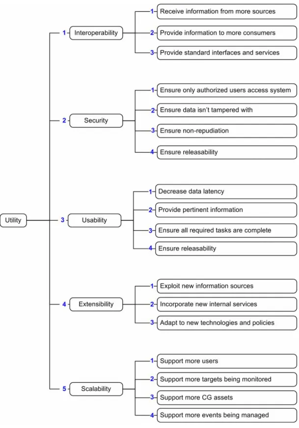
1. Utility Tree ... 50
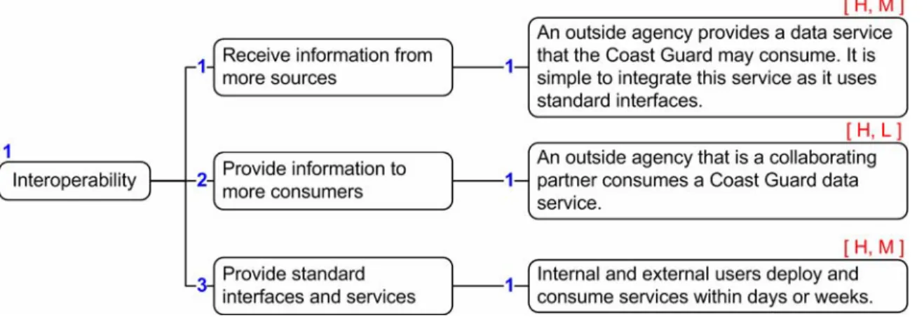
2. Quality Attribute – Interoperability (1.0.0)... 52
3. Quality Attribute – Security (2.0.0) ... 52
4. Quality Attribute – Usability (3.0.0) ... 53
5. Quality Attribute – Extensibility (4.0.0) ... 54
6. Quality Attribute – Scalability (5.0.0)... 55
7. Operational Examples ... 56
F. CONCEPTUAL DATA MODEL (CDM) ... 58
1. Planning Element... 58 2. Mission Element ... 59 3. Task Element... 60 4. Asset Element ... 61 5. Target Element... 62 6. CDM Conclusion ... 63
7. Information Exchange Models... 63
8. Maritime Information Exchange Model (MIEM) ... 64
G. PRODUCT LINE ARCHITECTURE FOR COMPOSITE APPLICATIONS... 65
2. Product Line Architectures... 66
3. Mashability ... 67
4. Conclusion ... 68
IV. IMPLEMENTATION PLAN ... 71
A. INTRODUCTION ... 71
B. DASH-CREIGH IDeA METHOD... 73
1. Introduction... 73
2. Architecture Loop... 73
3. Service Development Loop (SDL) ... 77
4. IDeA Conclusion ... 79
C. ORGANIZE FOR SUCCESS... 80
D. BEST PRACTICES AND WORST PRACTICES... 81
E. SOA’S IMPACT ON QUALITY ATTRIBUTES ... 85
F. CONCLUSION ... 89
V. CONCLUSIONS AND RECOMMENDATIONS... 91
A. CONCLUSION ... 91
B. RECOMMENDED FUTURE RESEARCH ... 92
1. Coast Guard Data Models ... 92
2. Planning Services Based on MHS-OPS ... 92
3. Operations Watchstander Console ... 92
4. PKI for SOA ... 93
5. XMPP for Coast Guard Command and Control... 93
LIST OF REFERENCES... 95
BIBLIOGRAPHY ... 99
APPENDIX A. U.S. COAST GUARD ORGANIZATIONAL RELATIONSHIPS .... 103
A. WITHIN THE FEDERAL GOVERNMENT ... 103
B. WITHIN THE COAST GUARD ... 103
C. WITHIN THE SECTOR... 104
D. CONCLUSION ... 106
APPENDIX B. COMMUNICATIONS INTEROPERABILITY... 107
A. NETWORK-CENTRIC... 107
B. REQUIRED NETWORK CAPABILITIES ... 108
1. Availability... 108
2. Quality of Service (QoS)... 108
3. Public Key Infrastructure (PKI)... 109
4. SNMP for Remote Management... 110
C. WEB SERVICES STACK... 110
1. Process Layer ... 111
2. Description Layer ... 111
3. Messages Layer ... 111
4. Communications Layer ... 111
APPENDIX C. SEARCH PATTERN WEB SERVICE SOURCE CODE ... 113
A. CODE OVERVIEW... 113
B. SEARCH PATTERN CLASS ... 113
C. SEARCH CLASS ... 114
D. NAV CLASS... 116
E. POSITION CLASS ... 117
F. WEB SERVICE DESCRIPTION LANGUAGE (WSDL) ... 118
APPENDIX D. SEARCH PATTERN CLIENT SOURCE CODE ... 121
A. CODE OVERVIEW... 121
B. SEARCH PATTERN SWING CLIENT ... 121
LIST OF FIGURES
Figure 1. Efficient Thought (From: Hayes-Roth Hyper-beings Fig 2.)... 6
Figure 2. Coast Guard Command Center System Model (From: Command Center Program Manual Figure 1-2-1)... 7
Figure 3. Web Services Architecture Stack (After “Web Services Architecture” Figure 3-1)... 18
Figure 4. Java Client – Sector Search ... 25
Figure 5. CGC2 SOA Functional Areas and Actors (OV-1) ... 28
Figure 6. CGC2 SOA Operational Node Connectivity (OV-2)... 29
Figure 7. CGC2 SOA Systems Interface Description (SV-1) ... 30
Figure 8. Utility Tree (top level)... 51
Figure 9. Utility Tree – Interoperability ... 52
Figure 10. Utility Tree – Security ... 53
Figure 11. Utility Tree – Usability... 54
Figure 12. Utility Tree – Extensibility ... 55
Figure 13. Utility Tree – Scalability ... 56
Figure 14. Data Model – Planning Element ... 59
Figure 15. Data Model – Mission Element ... 60
Figure 16. Data Model – Task Element ... 61
Figure 17. Data Model – Asset Element ... 62
Figure 18. Data Model – Target Element... 62
Figure 19. MIEM – Maritime Object ... 65
Figure 20. Example Composite Application ... 66
Figure 21. Command and Control SOA as PLA ... 67
Figure 22. Theoretical Capability Derived Over Time ... 71
Figure 23. Actual Capability Derived Over Time... 72
Figure 24. IDeA Architecture Loop ... 76
Figure 25. IDeA Service Development Loop ... 78
Figure 26. SOA Best Practices and Worst Practices ... 82
Figure 27. Quality Attribute Importance for CGC2 SOA ... 86
Figure 28. SOA Support for Quality Attributes ... 86
Figure 29. Coast Guard Operational Chain of Command... 103
Figure 30. U.S. Coast Guard Sector Commands (From: Command Center Program Manual Figure 2-1-1) ... 104
Figure 31. Sector Command Center Duties (After: Command Center Program Manual Figure 2-2-2) ... 105
Figure 32. Web Services Architecture Stack (After “Web Services Architecture” Figure 3-1)... 111
LIST OF TABLES
Table 1. Search Pattern Service Parameters ... 23
Table 2. Operational Examples and Corresponding Quality Attributes... 57
Table 3. IDeA Architecture Loop – Steps and Outputs... 74
Table 4. IDeA Service Development Loop – Steps and Outputs ... 77
Table 5. SOA Quality Attribute Impact (After: O’Brien, Bass, and Merson Table 1) ... 87
ACRONYMS AND ABBREVIATIONS
ADO Assistant Duty Officer
AIS Automatic Identification System
AMVER Automated Merchant Vessel Reporting
AOPS Abstract of Operations
BPEL4WS The Business Process Execution Language for Web Services
BPMN Business Process Modeling Notation CASP Computer Aided Search Planning
C2 Command and Control
C2CEN Command and Control Engineer Center
CC Command Center
CCPM The Coast Guard Command Center Program Manual
CDM Conceptual Data Model
CDNU Cockpit Display Navigational Unit
CDO Command Duty Officer
CG Coast Guard
CGC Coast Guard Cutter
CGC2 Coast Guard Command and Control CGDN Coast Guard Data Network
CGMS Coast Guard Message System CMA Comprehensive Maritime Awareness
CO Commanding Officer
COI Communities of Interest
COPORD Common Operational Picture Operational Requirements Document
CTO Chief Technical Officer
DHS Department of Homeland Security
DoD Department of Defense
DoDAF DoD Architecture Framework ELT Emergency Locator Transmitter eNOAD Electronic Notice of Arrival/Departure
EPIRB Emergency Position Indicating Radiobeacon FTP File Transfer Protocol
GPS Global Positioning System GUI Graphical User Interface HTTP Hypertext Transfer Protocol
ICS Incident Command System
IDeA Incremental Development Approach
IP Internet Protocol
IT Information Technology JAWS Joint Automated Worksheet
JC3IEDM Joint Consultation Command & Control Information Exchange Data Model
JCTD Joint Capability Technology Demonstration JRCC Joint Rescue Coordination Center
LEDET Law Enforcement Detachement LEDO Law Enforcement Duty Officer LNM Local Notice to Mariners
M/V Motor Vessel
MIEM Maritime Information Exchange Model
MISLE Marine Information for Safety and Law Enforcement
MHS-OPS Maritime Homeland Security Operational Planning System MSRT Maritime Security Response Team
MSST Maritime Safety and Security Team NCO Network Centric Operations
NIEM National Information Exchange Model
NMS Network Management System
NPS Naval Postgraduate School
OPAREA Operational Area
OPCEN Operations Center
OPTEMPO Operational Tempo
OSC Operations Systems Center
PAWSS Ports and Waterways Safety System PLB Personal Locator Beacons
PKI Public Key Infrastructure
QoS Quality of Service
R21 Rescue 21
R21DF Rescue 21 Direction Finder
SAML Security Assertion Markup Language SANS Ship Arrival and Notification System
SAR Search And Rescue
SARSAT SAR Satellite
SDL Service Development Loop
SEI Software Engineering Institute
SITREP Situation Report
SMTP Simple Mail Transfer Protocol
SNMP Simple Network Management Protocol SOA Service Oriented Architecture
SOAP Simple Object Access Protocol SPS Search Pattern Service
TCP Transmit Control Protocol
TISCOM Telecommunications and Information Systems Command UDDI Universal Description Discovery and Integration
USCGC United States Coast Guard Cutter USMCC United States Mission Control Center VBST Vessel Boarding and Search Team
VHF Very High Frequency VMS Vessel Monitoring System VTS Vessel Traffic Service
W3C World Wide Web Consortium
WAN Wide Area Network
WSDL Web Service Description Language XML Extensible Markup Language
XMPP Extensible Messaging and Presence Protocol
XO Executive Officer
XSD XML Schema Documents
ACKNOWLEDGMENTS
We would like to thank Dr. Rick Hayes-Roth, Rex Buddenberg, Dr. Alex Bordetsky, and Glenn Cook for your dedication and devotion to our educational journey. Your support and direction made our experience at the Naval Postgraduate School worthwhile. We both feel fortunate to have been your students.
LCDR Rusty Dash
To Danielle, this wouldn’t exist without you. Thanks for giving way more than you received.
To Bradley, Bryce, and Brendon, one day you might actually peruse this thesis thing and wonder why it stole so much time otherwise reserved for us. Thanks for being great boys and giving me time to get this thesis done.
To Brian Rideout and the various members of Group TLR, thanks for the adventures in class projects and academic excellence. Friends like you made my time here “a awesome” experience.
To Bob, my thesis partner, thanks for such a great thesis topic. It meant a lot to have another Coastie to go through NPS with. Oh, and one more thing, I just found another great article that we can use in chapter…
LT Bob Creigh
To my wife Jill, thank you for supporting me throughout my career and during this time at NPS. Your love and devotion have not gone unnoticed.
To Andy and Heather, for all of the time I spent on this instead of with you doing things that we love to do.
To Rusty, you provided me almost as much education during my time here as the faculty. Thank you for all your effort toward writing this thesis and for being a good and trusted friend.
I. INTRODUCTION
A. BACKGROUND
The roles and missions of the United States Coast Guard have changed significantly from the vision of its founding father, Alexander Hamilton, who stated that “A few armed vessels, judiciously stationed at the entrances of our ports, might at a small expense be made useful sentinels of the laws.” (Hamilton 1787) Today’s Coast Guard is a dynamic, multi-mission maritime organization dedicated to protecting the lives, safety, and security of the American people. This service is a unique combination of military combatant, law enforcement authority, and humanitarian do-gooder that the government and American public have come to expect will always be “Semper Paratus.” As such, it has been assigned a diverse set of strategic goals and missions that require partnership and interoperability with many local, state, federal, and international agencies, as well as the maritime industry and foreign governments. The five strategic goals and twenty major missions of the United States Coast Guard are:
Maritime Safety – Eliminate deaths, injuries, and property damage associated with maritime transportation, fishing, and recreational boating. The specific missions are Search and Rescue (SAR), Marine Safety Program, Recreational Boating Safety, and the International Ice Patrol.
National Defense – Defend the nation as one of the five U.S. armed services. The specific missions include Defense Readiness, Homeland Security, Ports Waterways and Coastal Security, and Polar Icebreaking.
Maritime Security – Protect America's maritime borders from all intrusions by: (a) halting the flow of illegal drugs, aliens, and contraband into the United States through maritime routes; (b) preventing illegal fishing; and (c) suppressing violations of federal law in the maritime arena. The specific missions are Illegal Drug Interdiction, Migrant Interdiction, Living Marine Resource Protection,
General Maritime Law Enforcement, Exclusive Economic Zone Enforcement, and Treaty Enforcement.
Maritime Mobility – Facilitate maritime commerce and eliminate interruptions and impediments to the efficient and economical movement of goods and people, while maximizing recreational access to and enjoyment of the water. The specific missions are Aids to Navigation, Icebreaking Operations, and Vessel Traffic/Waterways Management.
Protection of Natural Resources – Eliminate environmental damage and the degradation of natural resources associated with maritime transportation, fishing, and recreational boating. The specific missions include Marine Environmental Science, Foreign Vessel Inspections, and Marine Pollution Response and Enforcement. (“Missions”)
Coastguardsmen are policemen, sailors, warriors, humanitarians, regulators, stewards of the environment, diplomats, and guardians of the coast while performing those missions. (America’s Maritime Guardian 2) Each of those duties has unique requirements for the type, amount, and complexity of information that must be managed. This information diversity is plainly visible when one considers the list of activities and accomplishments during an “average Coast Guard day.”
Every day the U.S. Coast Guard:
• Conducts 82 search and rescue cases
• Saves 15 lives
• Assists 114 people in distress
• Protects $4.9 million in property
• Boards 202 vessels of law enforcement interest
• Interdicts 26 illegal migrants at sea
• Conducts 23 waterfront facility safety or security inspections
• Enforces 129 security zones
• Monitors the transit of 2,557 commercial ships through U.S. ports
• Boards 122 large vessels for port safety checks
• Boards 4 “high interest” vessels
• Investigates 20 vessel casualties involving collisions, allisions and groundings
• Responds to 11 oil and hazardous chemical spills
• Conducts 317 vessel safety checks
• Teaches 63 boating safety courses
• Conducts 19 commercial fishing vessel safety exams
• Processes 280 mariner licenses and documents
• Services 140 aids to navigation
(“Average Day”)
With such a high volume of daily activity in so many different mission areas, the Coast Guard faces a daunting information and communication problem. It needs to efficiently process and effectively utilize large amounts of varied information that typically originates from unplanned events. Unfortunately the Coast Guard is burdened with an information technology (IT) infrastructure composed of standalone applications and communications networks that lack interoperability. The combination of heterogeneous missions, applications, and networks creates information sharing problems within the Coast Guard and with external entities that result in operational inefficiency and ineffectiveness. In addition the Coast Guard has become an integral part of the rapidly evolving, extended homeland security enterprise that spans multiple federal departments and reaches out to many state and local government agencies. This means the
information sharing needs of the Coast Guard are ever growing and will be increasingly influenced by its partners, both within the federal government and beyond. The September 11th 2001 terrorist attacks and Hurricane Katrina highlighted weaknesses in our nation’s intra- and inter-agency information sharing and “demonstrated the critical need for developing improved (distributed, shared and fault-tolerant) enterprise governance systems that are at once stand-alone and interoperable.” (Bayne 14) In response to these challenges, the Coast Guard must develop a credible architecture and then adopt a flexible, rapid, and incremental implementation process.
B. SOFTWARE ARCHITECTURE
Enterprise level software architectures connect business goals and computer systems by describing the structures of the software elements, including the externally visible properties of the elements, and the relationships and interactions between them. “Externally visible” properties refers to those assumptions that other elements can make about the behavior of an element, such as its provided services and performance characteristics. The details of elements that have solely to do with internal implementation are by definition not architectural. The architecture provides the fundamental organization of the system and the principles that govern its design and evolution. (“Published Software Architecture Definitions”)
Successful software architectures are designed to meet both functional and quality attribute requirements. The functional requirements define what the software components do, and these are typically written in brief scenarios called use cases. An example of a functional requirement is: given the necessary six input parameters (Commence Search Point, Length, Width, Major Axis, Track Spacing, First Turn), calculate the waypoints for a parallel search pattern as defined by the National SAR Manual and output them in Extensible Markup Language (XML) format that complies with the Joint Consultation Command & Control Information Exchange Data Model (JC3IEDM) schema. Quality attributes are the benchmarks that describe a system’s intended behavior within the
environment for which it was built. They provide the means for measuring the fitness and suitability of a product. Quality attribute requirements such as those for performance, security, modifiability, reliability, and usability have a significant influence on the software architecture of a system. (“Software Architecture Glossary”)
1. Software Architecture for Command and Control
The Coast Guard does not have a viable enterprise level software architecture that meets its current needs, let alone its rapidly evolving future needs. It is burdened with a collection of “stovepipe systems” that were individually created to address specific functional needs, without consideration or design for current functionality and quality-attribute requirements. Each stovepipe embeds the semantics of the data and the processing logic (functions) within the system. This configuration prevents other programs from accessing either the data or functions, effectively trapping them within the stovepipe. Because it is extremely difficult to integrate stovepipes, new systems often repeat data and functions which produces two serious problems. The first problem is that data about the same object (vessel, report, etc.) often differs from one stovepipe to the next, which creates confusion and uncertainty for the users. The second problem is the limitation in the number of systems a human can simultaneously utilize. Relevant data and useful functionality may go unused because they are too difficult to access and not all users have access to every stovepipe. To solve this problem the Coast Guard must integrate the data and functionality from the stovepipes in an new architecture that supports its rapidly evolving needs.
This thesis will focus on the development of a software architecture for Coast Guard Command and Control. Coast Guard Publication 1 defines Command and Control as “the exercise of authority and direction by a properly designated commander over assigned and attached forces in the accomplishment of the mission.” This includes planning, directing, coordinating, and controlling forces and operations to accomplish the mission. (America’s
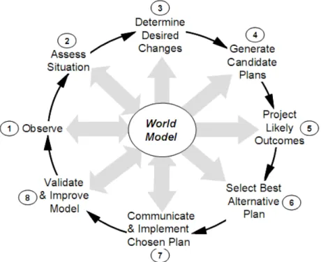
Maritime Guardian 60) Many theories about command and control break the decision making process into sense-decide-act stages that form an iterative loop. Dr. Rick Hayes-Roth further refines this theory by defining efficient thought by intelligent beings (person, organization, system). The functions of efficient thinking divide into eight steps, each supported by a world model that represents the intelligent being’s understanding of how things work. “The world model provides the knowledge that an intelligent being uses to interpret events, generate candidate plans for improving situations, and select the most attractive candidates for execution.” (Hayes-Roth, Hyper-beings 58)
Figure 1. Efficient Thought (From: Hayes-Roth Hyper-beings Fig 2.)
The eight steps of efficient thought are numbered in a typical sequence, though in most complex organizations all eight steps operate in parallel. “The intelligent being (1) observes what’s happening in the environment, (2) assesses the situation for significant threats and opportunities, (3) determines what changes are desirable, (4) generates candidate plans for making those changes, (5) projects the likely outcomes of those plans, (6) selects the best plan, and (7)
communicates that plan to key parties and implements it. Throughout, the intelligent being (8) validates and improves its model. The model supports all eight activities, although only steps 1, 2, 7 and 8 directly update and modify the model.” (Hayes-Roth Hyper-beings 59) Software architecture for command and control needs to support the use of these eight steps.
2. Coast Guard Command and Control Architecture
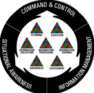
The Coast Guard Command Center Program Manual (CCPM) describes a system model that depicts the fundamental components of command center performance as seven capabilities that produce three outputs. This system model relies upon the interaction between the capabilities of planning, execution, information collection, information processing, information sharing, awareness, and assessment to produce information management, situational awareness, and command and control. While not identical, many similarities exist between the Coast Guard’s model and Dr. Hayes-Roth’s efficient thought process described above.
Figure 2. Coast Guard Command Center System Model (From: Command Center Program Manual Figure 1-2-1)
The authors of the CCPM use a triangle of triangles to represent each of the seven capabilities in the system model. Each “capability” triangle is composed of three smaller triangles; a blue one representing agents (human and software) to perform tasks, a green one representing infrastructure (computers, sensors, etc.), and a red one representing doctrine. The manual lists 35 different stovepipe software applications watchstanders can use to perform their duties. However, the system model does not describe how these elements function and interact to produce the required outputs. Absent this critical analysis and documentation, the current system model will never reliably produce the desired results.
Clearly the Coast Guard needs to find new and better ways of managing information and providing capabilities in response to quickly changing needs. It needs to design a component-based architecture that provides the necessary functionality with the required quality attributes. The Coast Guard will always have limited resources and its command and control requirements will continue to change over time. Therefore, any new architecture must facilitate integration with legacy systems in a way that reuses existing assets and allows flexible reconfiguration of both existing and new assets as needed. The architecture should also enable an evolution from the current state to required functionality that delivers value at each step along the way.
3. Service-Oriented Architecture (SOA)
The Commandant of the Coast Guard has mandated the implementation of a Service-Oriented Architecture to “better serve the needs of all our internal and external customers.” (Allen) The SOA methodology will supposedly enable the Coast Guard to reduce the expense of integration, increase asset reuse, and increase business (organizational) agility. SOA encapsulates the distinct functions contained in enterprise applications into loosely-coupled, interoperable, standards-based services that interact via a common communications protocol. “A service is an implementation of a well-defined piece of business functionality, with a published interface that is discoverable and can be used by service
consumers when building different applications and business processes.” (Obrien 1) These services are combined and reused to meet the requirements of business processes and software users.
The Coast Guard does not have resources to simultaneously redevelop legacy system functionality and implement the new elements of SOA. The rich capabilities contained within legacy Command and Control (C2) applications can be reused in an SOA with a “wrapper.” This approach provides a viable economic option, because it avoids re-writing the existing software. Once service enabled, these legacy components can remain operationally intact within the current architecture and be made available as services at the same time. “SOAs are flexible because each service encapsulates the underlying platforms and technologies that support it. The services provided at the enterprise level are therefore agnostic to those specific platforms and technologies.” (Lau 11)
Unfortunately SOA does not provide the perfect solution to all the Coast Guard’s information sharing and application integration needs. SOA means different things to different people and the Coast Guard needs to have a clear understanding of the differing technologies, standards, and implementation methods. Because SOA holds so much promise, all the major software manufacturers and vendors are promoting their support with some directly involved in developing open standards. As a result, every major development platform now officially supports the creation of “service-oriented solutions.” (“The SOA Vision”) This competition between vendors with different standards must be approached with caution as it may actually make it more difficult to successfully develop a meaningful SOA to meet the Coast Guard’s needs. The next chapter will examine the standards and technologies used to implement SOAs with specific recommendations.
C. THESIS QUESTIONS
This thesis aims to provide sound, supported, informative, and valuable answers to Coast Guard IT decision-makers for the following two questions.
1. How Can the Coast Guard Implement a Service-Oriented Architecture for Command and Control?
Traditional descriptions of software architectures make it difficult to identify and understand the trade-offs between quality attributes that are inherent in the design. We will use multiple scenarios and use cases, in addition to diagrams and functionality requirements, to make these critical issues easier to understand. Defining the architecture in terms of the functionality and quality attribute levels of each component should allow an auditor to determine the architecture’s validity. Our answer to this question does not create a complete architecture, however it does establish an effective starting point for the Coast Guard.
2. What is the Optimal Implementation Plan for this Coast Guard Command and Control (CGC2) SOA?
Almost all large scale software and IT system projects fail, so a “big bang” approach to create this SOA should be avoided. Because the entire SOA will not be created at the same time, the Coast Guard needs a process that will deliver value in the form of usable capabilities in an incremental and iterative manner. This sequence of capabilities should determine how the components and architecture evolve. Our proposed iterative method will include an evaluation of the system requirements, architecture, and implementation plan during each repetition of the cycle that guarantees continuous improvement. This plan will also incorporate industry best practices to anticipate and address predictable problems.
D. THESIS ORGANIZATION
Chapter I has defined the problem and introduced the basic approach for our solution. The remaining chapters of this thesis are organized as follows:
• Chapter II provides a synopsis of SOA components and standards.
• Chapter III describes an SOA for Coast Guard Command and Control.
• Chapter V contains our conclusions and recommendations for future research.
II.
SOA BACKGROUND INFORMATION
A. SERVICES ORIENTED ARCHITECTURE
This chapter provides background information about SOA, Web services standards, and data models for readers new to the subject so they can grasp the material presented in the remaining chapters.
Service-Oriented Architecture is a software design methodology that uses loosely-coupled services to perform business functions or processes. These services communicate using well-defined standards across a network. Section C describes services and service-oriented design principles in detail. Services send XML-formatted messages that relay information structured in accordance with an accepted data model. Section B defines the basic XML terms and Section E discusses data models.
SOA proponents believe it can help businesses (and government agencies) respond more quickly and cost effectively to changing environmental conditions. “All major software manufacturers and vendors promote support for SOA – some even through direct involvement in the development of open standards. As a result, every major development platform now officially supports the creation of service-oriented solutions.” (“The SOA Vision”) While that statement sounds like a boon for businesses and government organizations considering an SOA, competing standards and vendors can actually make it more difficult to separate the marketing hype from the truly valuable technology to determine a path to success. We outline the core SOA standards in Section D. This chapter concludes with an example Web service in Section E.
B. XML
The Extensible Markup Language (XML) is an open standard for exchanging structured documents and data over the Internet. Authors and “…designers create their own customized tags, enabling the definition, transmission, validation, and interpretation of data between applications and
and storing different elements of information. XML Schema Documents (XSD) use XML to describe the schema for a certain kind of XML document or message. An XML message recipient can use the appropriate XSD to verify the message’s data structure and format using a process called validation. Using XML to carry both the meta data and the data in the same message, composed using an agreed upon schema, begins to solve the data interoperability problem.
Because XML documents contain standard structure with the content, they can be easily converted to comply with another XML schema. XML Transformation documents, written in the Extensible Stylesheet Language Transformation (XSLT) language, perform this function. For example, we may have one XSLT that reformats an XML message as a Web page, another that outputs a plain-text document for printing, and a third that outputs data formatted as expected by a legacy application. To summarize, we use XML to “tag” content in a message, XSD to define the structure of the tags, and XSLT to reorganize the data based on the needs of a specific consumer.
C. SERVICES
“A service is an implementation of a well-defined piece of business functionality, with a published interface that is discoverable and can be used by service consumers when building different applications and business processes.” (O’Brien, Bass, and Merson 1) Web services differ from generic services because they use SOAP-formatted XML envelopes and have their interfaces described by a Web Service Description Language (WSDL) document. Section D defines both SOAP and WSDL. We use the terms service and Web service interchangeably throughout this thesis. The decision to use one or the other will be made by the architecture team for each service, when it designs the SOA.
1. Common Principles of Service Orientation
The authors of a recent Software Engineering Institute report on SOA provide the following service oriented design principles. They establish a unique design approach for building Web services for SOA. “When applied, these
principles succeed in standardizing Web services while preserving their loosely coupled relationships.” (Erl 53)
Services are reusable. Regardless of whether immediate reuse opportunities exist, services are designed to support potential reuse.
Services share a formal contract. In order for them to interact, they need not share anything but a formal contract that defines the terms of information exchange and any supplemental service description information.
Services are loosely coupled. They must be designed to interact on a loosely coupled basis, and they must maintain this state of loose coupling. This is closely related to service abstraction and service autonomy. [Loosely coupled frameworks allow individual nodes in a distributed system to change without affecting or requiring change in any other part of the system.]
Services abstract underlying logic. The only part of a service that is visible to the outside world is what is exposed via the service’s description and formal contract. The underlying logic (beyond what is expressed in the description and formal contract) is invisible and irrelevant to service requestors.
Services are composable. They may compose other services. This possibility allows logic to be represented at different levels of granularity and promotes reusability and the creation of abstraction layers.
Services are autonomous. The logic governed by a service resides within an explicit boundary. The service has complete autonomy within this boundary and is not dependent on other services for the execution of this governance.
Services are stateless. They should not be required to manage state information, since that can impede their ability to remain loosely coupled. Services should be designed to maximize statelessness even if that means deferring state management elsewhere.
Services are discoverable. They should allow their descriptions to be discovered and understood by humans and service users who may be able to make use of the services’ logic. Service discovery can be facilitated by the use of a directory provider, or, if the
address of the service is known during implementation, the address can be hard-coded into the user’s software during implementation. Services have a network-addressable interface. Service requestors must be able to invoke a service across the network. When a service user and service provider are on the same machine, it may be possible to access the service through a local interface and not through the network. However, the service must also support remote requests.
Services are location transparent. Service requestors do not have to access a service using its absolute network address. Requestors dynamically discover the location of a service looking up a registry. This feature allows services to move from one location to another without affecting the requestors. (O’Brien, Bass, and Merson 3-4)
2. Wrappers
Architects often want to reuse existing applications and databases in their SOAs. Unfortunately almost all legacy systems cannot operate in the service environment in their current configuration. Developers solve this problem by creating a wrapper, special software that resides between the legacy application and the SOA. The wrapper exposes the legacy application’s functionality or data to the SOA as a service. The wrapper provides all the security, quality of service, and service orientation principles that any other service in the SOA has. The following quote illustrates the benefits wrappers can provide:
For example, at telecom company Verizon, the service called "get CSR" (get customer service record) is a complex jumble of software actions and data extractions that uses Verizon's integration infrastructure to access more than 25 systems in as many as four data centers across the country. Before building the "get CSR" service, Verizon developers who needed that critical lump of data would have to build links to all 25 systems—adding their own links on top of the complex web of links already hanging off the popular systems. But with the "get CSR" service sitting in a central repository on Verizon's intranet, those developers can now use the simple object access protocol (SOAP) to build a single link to the carefully crafted interface that wraps around the service. Those 25 systems immediately line up and march, sending customer information to the new application and saving developers months,
even years, of development time each time they use the service. (“ABCs of SOA”)
Wrappers provide an excellent way to reuse applications already delivering business value. However, proper IT business alignment is necessary to ensure proper enforcement of control and management policies. Randomly wrapping services can lead to security and performance problems inside and outside the organization. The Web service wrappers provide a “great tactical approach” for SOA development, but they are not a panacea. (“Web Services Wrapper”) We can not simply wrap all our legacy systems and declare SOA victory. Ultimately, SOA aims to unlock the application logic and data from the legacy systems, so they exist as native services within the SOA. This process frees them to operate at their logical place in the business processes and workflows, without the artificial constraints of the legacy systems.
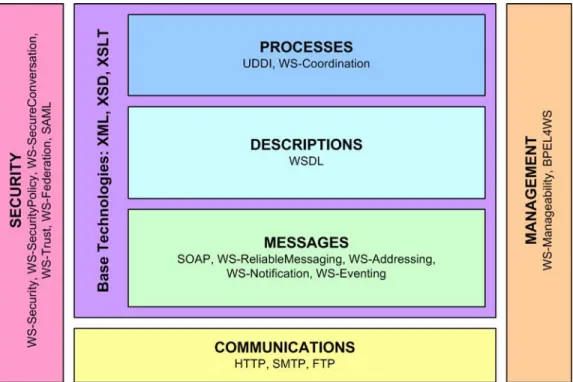
D. WEB SERVICE STACK
The Web services stack shows the collection of computer networking protocols that define, locate, implement, and make Web services interact with each other. The World Wide Web Consortium’s Web Services Architecture Working Group defined technical standards to ensure interoperability for SOAs. The Working Group divided these standards into the following six areas: processes, descriptions, messages, communications, security and management: Figure 3 shows a modified version of their Web Services Architecture Stack diagram.
Figure 3. Web Services Architecture Stack (After “Web Services Architecture” Figure 3-1)
1. Process Layer
The Process layer describes how providers publish services and requestors/consumers discover them. The Process layer utilizes the following standards:
• Universal Description Discovery and Integration (UDDI): UDDI is a directory that allows businesses to register their services so that the consumers can find them.
• WS-Coordination: This specification “describes an extensible framework for providing protocols that coordinate the actions of distributed applications. Such coordination protocols are used to support a number of applications, including those that need to reach consistent agreement on the outcome of distributed activities.” (“WS-Coordination”)
2. Description Layer
The Description layer describes how the service provider communicates the specifications for invoking the Web service to the service requestor. The Description layer utilizes the following standards:
• Web Service Description Language (WSDL): An XML document that describes the interfaces and methods that a service provides.
3. Messages Layer
The Messages layer describes how the services pass information in the form of a message. The Messages layer utilizes the following standards:
• Simple Object Access Protocol (SOAP): SOAP is a protocol used to exchange messages between systems in XML format. SOAP has become the de-facto standard protocol for Web services.
• WS-ReliableMessaging: This specification describes a protocol that allows messages to be transferred reliably between nodes in the presence of software component, system, or network failures. (“WS-ReliableMessaging”)
• WS-Addressing: This specification “provides transport-neutral mechanisms to address Web services and messages. Specifically, this specification defines XML elements to identify Web service endpoints and to secure end-to-end endpoint identification in messages. This specification enables messaging systems to support message transmission through networks that include processing nodes such as endpoint managers, firewalls, and gateways in a transport-neutral manner.” (“WS-Addressing”)
• WS-Notification: “The Event-driven, or Notification-based, interaction pattern is a commonly used pattern for inter-object communications. Examples exist in many domains, for example in publish/subscribe systems provided by Message Oriented Middleware vendors, or in system and device management domains.” (“WS-Notification”)
• WS-Eventing: “This specification describes a protocol that allows Web services to subscribe to or accept subscriptions for event notification messages.” (“WS-Eventing”)
4. Communications Layer
The Communications layer describes how messages are physically transported across the network. The Communications layer utilizes the following Internet protocols:
• Hypertext Transfer Protocol (HTTP): HTTP is the standard mechanism for retrieving Web pages and associated content. It can also be used for transmitting data from the client to the server.
• Simple Mail Transfer Protocol (SMTP): SMTP is the standard mechanism for sending email from the client to the server.
• File Transfer Protocol (FTP): FTP is primarily used for transferring files from one computer to another over a TCP/IP network.
5. Security
Security occurs at all layers in the stack and it provides authenticity, integrity, confidentiality, and non-repudiation. Security utilizes the following standards:
• WS-Security: “This specification describes enhancements to SOAP messaging to provide message integrity and confidentiality. The specified mechanisms can be used to accommodate a wide variety of security models and encryption technologies.” (“WS-Security”)
• WS-SecurityPolicy: WS-SecurityPolicy is designed to work with the general Web Services framework including WSDL service descriptions, UDDI businessServices and bindingTemplates and SOAP message structure and message processing model, and WS-SecurityPolicy should be applicable to any version of SOAP. (“WS-SecurityPolicy”)
• WS-SecureConversation: "This specification defines extensions that build on WS-Security to provide a framework for requesting and issuing security tokens, and to broker trust relationships.” (“WS-SecureConversation”)
• WS-Trust: The goal of WS-Trust is to enable applications to construct trusted SOAP message exchanges. This trust is represented through the exchange and brokering of security tokens. This specification provides a protocol agnostic way to issue, renew, and validate these security tokens. (“WS-Trust”)
• WS-Federation: A specification, by IBM and Microsoft, for standardizing the way companies share user and machine identities among disparate authentication and authorization systems spread across corporate boundaries. (“WS-Federation”)
• SAML: “An XML-based framework for communicating user authentication, entitlement, and attribute information. As its name suggests, SAML allows business entities to make assertions regarding the identity, attributes, and entitlements of a subject (an entity that is often a human user) to other entities, such as a partner company or another enterprise application.” (“SAML”)
6. Management
Management, like Security, occurs across all layers in the stack. Management provides methods for monitoring and managing services and
• WS-Manageability: “specification introduces the general concepts of a manageability model in terms of manageability topics and the aspects used to define them.” (“WS-Manageability”)
• Business Process Execution Language for Web Services (BPEL4WS): “The Business Process Execution Language for Web Services provides a comprehensive syntax for describing business workflow logic. It allows for the creation of abstract processes that can describe business protocols, as well as executable processes that can be compiled into runtime scripts” (Erl 100) The Business Process Modeling Notation (BPMN) provides a standardized graphical notation for drawing business processes in a workflow. Software tools easily translate BMPN models into BPEL4WS files.
E. DATA MODELS AND INFORMATION EXCHANGE
Semantics define a language’s structure and meaning. For the services in an SOA to be interoperable, the services exchanging messages must understand the semantics of the data. Therefore, we need an efficient way to establish an agreed upon structure and meaning for the data elements in our XML formatted messages. Conceptual data models and XML schemas accomplish this.
Conceptual data models (CDM) show the overall organizational data structure without considering the ability to implement the structure. SOAs employ CDMs to avoid the point-to-point mapping problem encountered when sharing data between systems. For example, if we have N systems in our SOA and we want them all to share data with each other, point-to-point mapping requires N(N-1) translations between them which is approximately N2. Utilizing a CDM requires 2N translations; one for each system to the CDM and one for the CDM back to each system, and this number is usually much smaller than N2. Interestingly, Appendix D to the Coast Guard’s Common Operational Picture Operational Requirements Document (COPORD) shows a matrix proposing point-to-point mapping between nine existing stovepipe systems. The 72 transformations required in the diagram could be reduced to 18, a reduction of 75%, through appropriate use of a CDM. The Coast Guard has not yet implemented a command and control CDM.
Creating a CDM has one negative aspect. The data modeling and related XML schema generation efforts increase the start-up cost. XML schemas describe an XML document’s structure and validate messages in the SOA. “This industry best practice requires work up front, but results in a scalable and flexible solution. The instantiation of a canonical XML Schema based on that model provides a consistent target … to which each endpoint system maps.” (Hutchins) Conceptual data modeling benefits outweigh their costs, in a way similar to the payback-to-cost provided by the Incremental Evolutionary approach in Chapter 4’s Figure 22.
F. EXAMPLE WEB SERVICE
1. Search Pattern Service (SPS) Description
We created the SPS to provide an example. It accepts search pattern parameters and returns the latitude and longitude points for the waypoints along the search. Coast Guard readers may initially dismiss the need for a service to generate search patterns. We already have many different systems capable of doing this, and several provide much more robust functionality. However, in addition to illustrating what a service can do, this particular example highlights a more important point. The Coast Guard has recreated the same functionality in a dozen different systems, but we can’t take a search pattern generated by the Sector Command Duty Officer (CDO) and automatically import it into the navigation system on a patrol boat.
Implementing functionality as a service means that you only need to build it once. Thereafter, anyone can use it anywhere in the SOA. Service modifications only happen in one location, not in each separate system. The SPS can also have multiple interfaces so that many different applications and devices can use it. This service calculates the same search pattern coordinates for every user. The Sector CDO sees the exact same pattern at his computer workstation that the coxswain on the small boat sees on his SINS equipment. The C-130 sees the same pattern on his Cockpit Display Navigational Unit (CDNU) as the District Commander using a smart phone. However, perhaps we
don’t want it to calculate the same pattern for every user. The interface can also make the service context-sensitive. For example, the small boat interface would generate search patterns that avoided rocky shoals but the helicopter interface would not.
2. Current Features
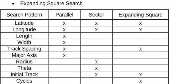
The SPS accepts the parameters shown in Table 1 then calculates and returns a series of latitude/longitude pairs. Appendix C contains the SPS source code. It currently performs three search patterns:
• Parallel Search
• Sector Search
• Expanding Square Search
Search Pattern Parallel Sector Expanding Square
Latitude x x x Longitude x x x Length x Width x Track Spacing x x Major Axis x Radius x Theta x Initial Track x x Cycles x
Table 1. Search Pattern Service Parameters
3. Potential Future Features
The initial description mentioned one potential feature, adjusting the pattern based on the asset type. It could also access current weather and sea conditions, or receive updated information about the target, and then dynamically adjust the search pattern parameters accordingly. Couple this capability with the integrated navigation systems in some of the Coast Guard’s assets and it becomes possible to improve mission effectiveness. Currently, changes to search patterns require the coxswain or pilot to manually stop the current search
and enter a new one with the updated information. Dynamic updates allow the people performing the mission to keep their eyes and attention focused on finding the survivor rather than buried in a navigation computer entering new coordinates.
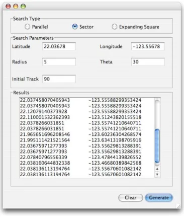
4. Java-based Client Application
We created a multi-platform Java-based client to demonstrate this service’s functionality and output. Appendix D contains the Java client source code. The user enters parameters into the form boxes and initiates the service by pressing the “Generate” button. This client initiates a request to the service and displays the result in the “Results” text box. Figure 4 shows the Java client in the sector search mode. Note that the latitude and longitude coordinates are in degrees with decimals. If we needed positions in degrees, minutes, seconds that conversion could be built into either the client application or the service itself. This client would probably not exist within the Coast Guard SOA. Most services do not need a dedicated user client. Integrated user interfaces, called composite applications, fuse the functionality and output of many services.
Figure 4. Java Client – Sector Search
G. CONCLUSION
This chapter defined important terms, introduced relevant concepts, identified applicable industry standards, and summarized SOA principles. Designing and building an SOA requires appropriate data standardization and modeling into XML schemas, adhering to the important industry standards to appropriately implement the technology needed to support the layers of the Web services stack. The next chapter defines an SOA for Coast Guard command and control to answer our first thesis question.
III. DRAFT USCG COMMAND AND CONTROL SERVICE
ORIENTED ARCHITECTURE (CGC2 SOA)
A. INTRODUCTION
This chapter provides the answer to our first thesis question, “How can the Coast Guard implement a Service-Oriented Architecture for Command and Control?” We begin with three diagrams in Section B; one to introduce the functional areas, one to describe the network nodes, and one to illustrate the systems interfaces. We then continue with a scenario in Section C that demonstrates the CGC2 SOA in action. Section D further describes the functional areas and identifies services to perform them. Section E discusses the quality attributes that significantly influence the architecture. Section F outlines the conceptual data model required to exchange data within the SOA. Finally, Section G proposes a product line architecture for producing composite applications. The answer to our first thesis question does not create a complete architecture. However it does establish an effective starting point for the Coast Guard.
B. ARCHITECTURAL VIEWS
“Software architecture represents a common abstraction of a system that stakeholders can use as a basis for creating mutual understanding, forming consensus, and communicating with each other.” (Clements, Kazman, Klien, 2)
Diagrams can elegantly summarize complex material, clearly showing details that otherwise get lost in lengthy text descriptions. Architectural views are diagrams that provide a mechanism for separating issues and concerns when analyzing or building an architecture. “They let us consider an architecture from different perspectives.” (Clements, Kazman, Klien, 8) The Department of Defense (DoD) uses a framework that “defines a common approach for DoD architecture description, development, presentation, and integration” called the DoD Architecture Framework. (DoDAF Deskbook 1-1) We created our diagrams as DoDAF “views” in order to facilitate comparison between our CGC2 SOA and
existing DoD and Coast Guard command and control systems. The following diagrams describe our proposed CGC2 SOA.
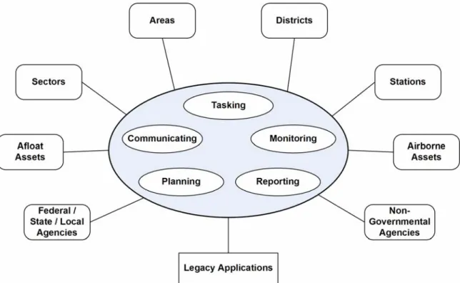
1. High Level Operational Concept (OV-1)
The OV-1 displays the primary CGC2 SOA actors. Participants include Coast Guard units, as well as federal, state and local governments and non-governmental agencies (e.g., harbor pilot associations and shipping companies). The five small ovals in Figure 5 represent the CGC2 SOA functional areas. The large blue oval represents the combined command and control effect those functions produce, making the whole greater than the sum of the parts.
Figure 5. CGC2 SOA Functional Areas and Actors (OV-1)
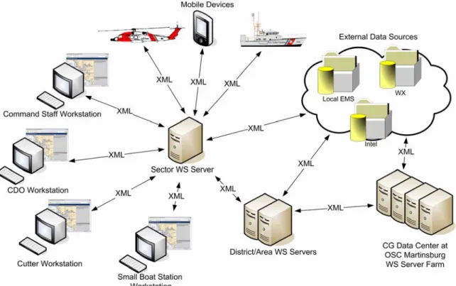
2. Operational Node Connectivity Description (OV-2)
The OV-2 shows all nodes that use, produce and consume information from services throughout the organization. These services send and receive messages formatted in the Extensible Markup Language (XML). The existing Coast Guard Data Network (CGDN) provides connectivity between network nodes, but does not reach mobile assets (e.g., aircraft and small boats).
Appendix B lists our proposed CGDN and communications systems requirements.
Figure 6. CGC2 SOA Operational Node Connectivity (OV-2)
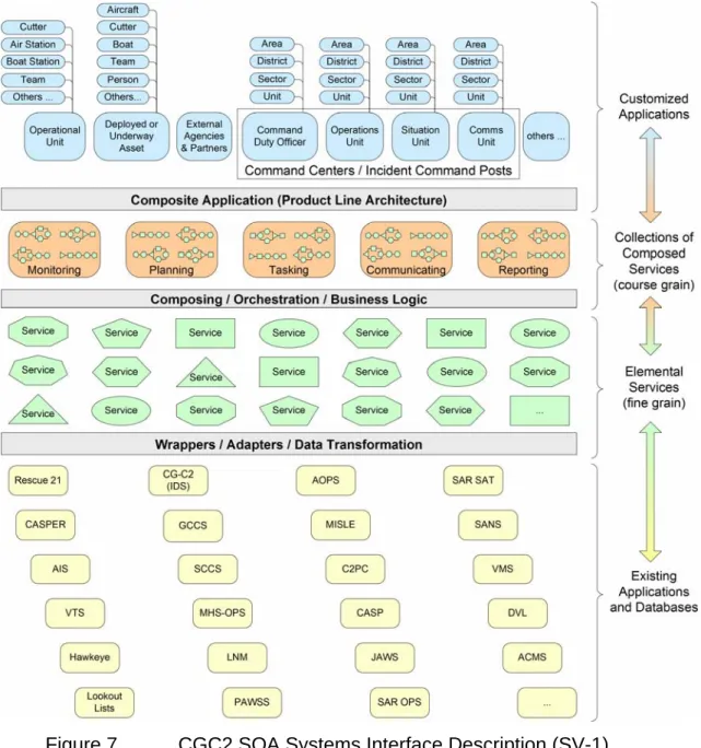
3. Systems Interface Description (SV-1)
The SV-1 identifies the interfaces between systems and system nodes. The diagram in Figure 7 shows the relationship between legacy systems, elemental and composed services, and the composite applications that utilize them. The gray horizontal boxes abstract many complex implementation details. Although each legacy system has unique requirements, SOA allows service providers and consumers to utilize any technology that supports the appropriate standards. While extremely important, these non-architectural issues will not be addressed in this thesis.
Figure 7. CGC2 SOA Systems Interface Description (SV-1)
The yellow boxes at the bottom of Figure 7 represent legacy applications that must be “service-enabled.” To do this, software called wrappers change the existing applications’ interfaces without affecting current functionality. Wrappers expose the business logic and data from legacy applications as services, which can be invoked (used) within the SOA. The wrappers also perform data transformation between the legacy application and the SOA’s context data
applications creates a pool of fine-grained services. The green shapes in Figure 7 represent all the fine-grained services. Each one typically performs a single business logic or data access function. Five different fine-grained service examples are: get local assets (e.g., cutters, boats, aircraft) currently in Alpha or Bravo status, get asset positions, get OPAREA weather, filter asset list based on weather limits, and sort asset list based on distance from present location to target.
As they pass through the middle gray box, the fine-grained services are assembled into processes, or workflows, that perform complex business functions. These processes or assemblies are known as coarse-grained services. The orange boxes in Figure 7 represent the five functional areas that logically group the course-grained services. The fine-grained services described in the paragraph above could be linked together to form a “nominate asset” service under Planning. This service would take a geographic position, perform those fine-grained services, and return a list containing available assets. Changing the fine-grained services’ input parameters can customize this coarse-grained service. For example, the “nominate surface” service would include cutters, boats, and Automated Merchant Vessel Reporting (AMVER) vessels, but the “nominate air” service would only return aircraft. Items from the coarse-grained services inventory can be reused as needed anywhere in the CGC2 SOA. In this way, we build functionality once, and then quickly deploy it across all units and mission areas.
The typical user interacts with the services through a composite application, shown as blue boxes at the top of Figure 7. A Command Duty Officer (CDO) needs a different composite application than the Sector Commander, which will differ from that needed by the district staff officer. Therefore we want an adaptive and inexpensive way to create a composite application tailored for each user type. We propose a product line architecture to create these composite applications in Section G. This will allow the Coast