PLACEMENT AND SCHEDULING OF NETWORK TRAFFIC ON
VIRTUAL NETWORK FUNCTIONS
Nicolas El Khoury
A thesis in
The Department of
Information Systems Engineering
Presented in Partial Fulfillment of the Requirements
For the Degree of Master of Applied Science in Information Systems Security Concordia University
Montréal, Québec, Canada
October 2016 c
Concordia University
School of Graduate Studies
This is to certify that the thesis prepared
By: Nicolas El Khoury
Entitled: Placement and Scheduling of Network Traffic on Virtual Network Functions
and submitted in partial fulfilment of the requirements for the degree of
Master of Applied Science in Information Systems Security
complies with the regulations of this University and meets the accepted standards with respect to originality and quality.
Signed by the final examining committee:
Chair
CIISE Examiner External Examiner Supervisor
Approved
Chair of Department or Graduate Program Director
20 Dean of Faculty C. Wang A. Youssef W. Hamouda C. Assi
Abstract
Placement and Scheduling of Network Traffic on Virtual Network Functions
Nicolas El Khoury
Hardware MiddleBoxes represent a vital part in today’s networks. Despite their important roles, they are accompanied by several problems, namely, their lack of flexibility, high capital and operational expendi-tures, and power consumption. Network Function Virtualization is one promising solution to address these problems. This trend replaces the MiddleBoxes by software-based entities. Indeed, these Virtual Network Functions promise to alleviate the numerous disadvantages brought by their hardware counterparts. One of these most serious issues is the steadily increasing power consumption. Studies suggest that the Virtual Network Functions will reduce the electricity costs needed to turn on and operate the hardware functions. In order to further optimize the power consumption of the network, an efficient framework, capable of placing and scheduling traffic on these VNFs, is needed. Such a framework allows to optimally map and schedule the flows to be serviced, and place the unused servers in energy saving modes. In this thesis, we assume VNFs are already placed on physical machines. We consider traffic flows with deadlines. We aim at assigning and scheduling flows to VNFs in the most energy efficient manner. We formulate this problem mathematically and, owing to its complexity, present an efficient algorithmic method for solving the problem. We compare our heuristic with two other approaches, one of which aims to minimize the makespan, and the other to minimize number of servers used. We show that our heuristic combines the advantages of both approaches and generates better results by consuming up to 31.3% and 46.1% energy less than other two approaches respectively. Further, we extend the existing work in the literature, and solve the problem of placement of traffic flows on VNFs while taking into account the transmission delay between pairs of VNFs, and the routing of the virtual links on the underlying physical network.
Acknowledgments
I would like to express my sincere gratitude to everyone who made this achievement possible, by giving technical and personal advice and motivation. I would like to begin by thanking Professor Chadi Assi. Truly, Professor Assi is an outstanding person. Throughout these two years, he has never stopped believing in my efforts, and always pushed me to bring the best in me. More importantly, he has always been available for either a technical help or a personal advice. In summary, I would like to say that I was very lucky to have worked under the supervision of professor Assi, and I owe him a lot.
Second, I would like to thank my family (my father Nabil, my mother Amal, and my brother Christophe), whom without their support, I would have never been able to complete their work. I would like to acknowledge the amount of advice, personnal and emotional help that I have received from them, especially during my down moments. I would like to especially thank my father, who is also my best friend. My father made everything possible. He is always the first one by my side in the beautiful and ugly moments. Whenever I was weak, my father pushed me back on my feet. I hope to God I can be as great as my father is.
Third, I would like to express my love and gratitude to my girlfriend Josette El Kreidy. I am blessed to have such an amazing, strong, educated, and intelligent woman who stood by my side during this journey, accompanying me everyday, and encouraging me to bring the best in me. Despite the distance between us, she never quit on me. Rather, she made it all possible with her kindness, and constant support.
Fourth, no words can express the greatness of my roommate, my best friend, and my brother Adel Belmona Zeineddine. Adel proved many times, that he is my best man. During my happiest moments, Adel was happier than me. During my worst moments, Adel, not only had to endure me, but he never quit on me, and always supplied me with advice to keep moving forward. I will never forget how Adel took care of
me after my accident, which left me with many broken bones. At that time, Adel took care of me, and made sure to cheer me up on a daily basis. Adel is not a friend. Adel is a brother, a best man, and a treasure to keep for life.
Fifth, I would like to thank my family in montreal: The Habib and Bitar families, Mr. Roland Dick, and Joe Kanaan. These people have been the biggest help to me in Montreal. While we are not blood related, they considered me as part of their families, and treated me as one of their own. Words cannot express how much I appreciate everything they have done to me during my stay in Montreal, especially in my early days where getting settled would have been extremely impossible without them.
Sixth, I would like to thank three special people that I have met in Montreal and became great friends: Sara Ayoubi, Ribal Atallah, and Elias Bou-Harb. These three friends, since day one, became special to me, because of their kind heart. They helped me a lot on both, the technical and personal level. I truly appreciate every moment I spent with them, and every piece of advice they have offered.
Seventh, I would like to sincerely thank the help and effort spent by Dr. Anna Lenkovskaya, especially during the last periods of my thesis. Dr. Lenkovskaya is an outstanding person with a kind heart, and a surreal determination to motivate people, and help them achieve their goals.
Finally, I would like to thank Professor Maurice El-Khabbaz for introducing me to Professor Chadi Assi, and every help he has offered to me during my stay in Canada. Professor El-Khabbaz is an outstanding person, and a wonderful friend.
Contents
List of Figures viii
List of Tables ix List of Algorithms x Abbreviations 1 1 Introduction 2 1.1 Background . . . 2 1.1.1 Cloud Computing . . . 2
1.1.2 Network Function Virtualization . . . 3
1.2 Problem Definition . . . 6
1.3 Reasoning . . . 7
1.4 Thesis Organization . . . 8
2 Related Work 9 2.1 ETSI NFV-MANO . . . 9
2.2 NFV Projects and Implemetations . . . 10
2.3 Virtual Network Function Placement and Scheduling . . . 14
2.4 NFV Frameworks and Architectures . . . 14
3 Energy-Aware Placement And Scheduling of Traffic Flows on VNFs 16 3.1 System Model . . . 17 3.1.1 Network Model . . . 17 3.1.2 Motivation . . . 19 3.1.3 Problem Statement . . . 21 3.1.4 Problem Formulation . . . 22 3.1.5 Model Scalability . . . 25 3.2 Algorithmic Solution . . . 26 3.2.1 Algorithm Explanation . . . 27 3.2.2 Benchmarks . . . 28 3.2.3 Algorithms in Action . . . 29 3.3 Numerical Results . . . 32 3.3.1 Model vs algorithms . . . 32 3.3.2 Compared Algorithms . . . 33 3.4 Conclusion . . . 38
4 Placement, Scheduling, and Routing of Traffic Flows on VNFs 39 4.1 The VNF Scheduling Problem . . . 40
4.1.1 Network Model . . . 40
4.2 The VNF Scheduling Problem . . . 41
4.2.1 Problem Formulation . . . 44
4.2.2 Model Scalability . . . 49
4.3 Conclusion . . . 49
5 Conclusion and Future Work 51 5.1 Conclusion . . . 51
List of Figures
1 Cloud Computing Business Model. . . 2
2 Service Function Chains. . . 5
3 Cloud Network Representation. . . 17
4 Schedules of Different Placement and Scheduling Scenarios . . . 21
5 Small Network State Illustration. . . 27
6 Schedules Produced by Different Algorithms. . . 30
7 Network Performance in Function of a Variable Workload. . . 36
8 Network Performance in Function of a Variable Deadline. . . 37
9 Small Network Example. . . 40
List of Tables
1 Scalability Results of the ILP Model. . . 26 2 Comparison Between the Model and the Algorithms . . . 32 3 Parameters and Values. . . 34
List of Algorithms
1 Energy Aware Consolidation(K, S). . . 26 2 Reduce Gap(si,K). . . 27
Abbreviations
SN . . . Substrate Network PS . . . Physical Server PL . . . Physical Link VN . . . Virtual Network VL . . . Virtual Link VM . . . Virtual MachineVNF . . . Virtual Network Function
MB . . . MiddleBox
CAPEX . . . Capital Expenditure
OPEX . . . Operational Expenditure
SLA . . . Service Level Agreement
NP-hard . . . Non-deterministic Polynomial-time hard
IaaS . . . Infrastructure as a Service
PaaS . . . Platform as a Service
SaaS . . . Software as a Service
released with minimal management effort or service provider interaction[2]. This computing model alleviates several burdens on both individual users and companies. Indeed, clients no longer need to worry about installing any hardware or software components, but rather, may just rent them. This concept is deemed feasible due to the virtualization of the hardware components in the data center. For instance, a Physical Server (PS) may host several Virtual Machines (VMs), each of which may run a different service.
In practice, the cloud architecture is divided into three groups (Figure 1), each of which offers a type of services:
• Infrastructure as a Service (IaaS):The provisioning of the physical resources (storage, computing, etc.). Examples of Iaas providers are Amazon EC2 [3], and GoGrid [4].
• Platform as a Service (PaaS): The provisioning of platform services, such as Operating Systems (OS) and development frameworks. Google App Engine [5], and Microsoft Windows Azure [6] are two main PaaS providers
• Software as a Service (SaaS):The provisioning of applications, used on demand, and accessed by the internet. Examples of SaaS Providers are RackSpace [7], and BroadSoft [8].
1.1.2
Network Function Virtualization
Cloud computing relies on virtualizing the general purpose PSs, and leasing them to clients. This concept paved the way into also virtualizing the network functions in the networks. Indeed, in addition to the general purpose PSs, the networks contain specialized servers who perform definitive functions in the networks. These specialized servers are called MiddleBoxes (MBs).
a MiddleBox is defined asany intermediary device performing functions other than the normal, standard functions of an IP router on the datagram path between a source host and destination host [9]. Examples of such NFs include, but are not limited to, Firewalls (restrict access to/from specific devices and applications), Network Address Translators (map IP addresses from one address realm to another), Proxies (relay messages between users and servers of an application) [10], etc. Indeed, MiddleBoxes have recently become a ubiquitous element in operators’ networks; today’s enterprises consist of a large number of hardware MBs in order to
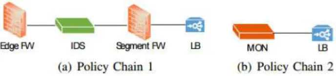
satisfy the diverse demands of the numerous flows travelling through the network. These MBs are physically placed at fixed locations in the network. Every traffic flow in need of a specific service must be routed to a MB offering that service itself. A flow may not necessarily request one network function only. Rather, it may require the traversal of an ordered set of service functions, a phenomenon calledService Function Chaining, also calledPolicy Chain [11]. Figure 2 illustrates two different SFCs. Evidently, the SFCs may differ in the number, and order of functions to be traversed by a flow. The IETF presents several SFCs use cases in data centers [12], and mobile [13].
In defiance of their increased popularity, MBs are also becoming more of a burden than a solution to network operators:
• The processing capacity of a hardware MB is fixed; such inflexibility limits their ability to optimally operate and concurrently being energy efficient. For example, in periods of low traffic, the MB will be running with full power, and therefore under-utilized. On the other hand, in cases of abundant traffic, it is not possible for MBs to serve more than their fixed capacities, causing potential congestion in the network. In order to handle these traffic surges, network operators tend to over-provision in the number and type of hardware NFs procured [14].
• Each function is deployed at a fixed physical location within the network. A request for a certain service chain might force the traffic to travel the network back and forth, thus occupying unnecessary bandwidth from some links.
• Hardware MBs are function-specific. It is not possible for one MB to provide more than one service, nor can it be reconfigured with another function. The lack of dynamic change renders the network vulnerable to excessive use of the resources to accommodate the constant changes in the traffic flowing.
• MBs come with high capital expenditure (CAPEX) and operational expenditure (OPEX). They are expensive to purchase, maintain, and operate. Furthermore, given the short-hardware lifecycle and the fast-pace technological advancements, adding new services and functionalities or replacing exist-ing hardware requires the procurement of more hardware NFs, which is a tedious and cumbersome procedure [15], [14].
Figure 2: Service Function Chains.
Network Function Virtualization (NFV) is a promising new technology that aims to tackle the afore-mentioned limitations of hardware NFs [15]. The tremendous benefits that virtualization has offered to multi-tenant cloud networks [16] has inspired the virtualization of middleboxes by decoupling the NFs from the hardware. NFV consists of virtualizing the middleboxes into software-based functions which can run atop any commerical-off-the-shelf (COTS) hardware [17] (standard servers, or routers/switches [18]). This greatly reduces the CAPEX in terms of hardware provisioning and energy cost, since these Virtualized NFs (VNFs) can be consolidated, deployed/removed, and migrated anywhere in the network. Moreover, VNFs support targeted instantiation, multi-tenancy, and elasticity (scale-up and scale-out) to fit the unpredictable and fluctuating nature of traffic demands; thereby alleviating any network resource wastage due to over-provisioning. These software-based NFs can also be easily upgraded/modified [15], thus, reducing OPEX required to maintain/configure them, and greatly enhancing the time-to-market.
Now, despite the immense benefits that NFV brings, several technical challenges need to be addressed to enable NFV to fulfil these aforementioned promises. Indeed, standardization bodies such as IETF [11] and ETSI [15], as well as recent studies [19, 20] have pin-pointed these challenges; among which we find concerns of management and orchestration, resource allocation, automation, security, etc. Accordingly, NFV has received significant attention from the literature in response to these calls for actions. While some [20–25] aimed at solving the orchestration and management concerns (i.e., the problem of finding the optimal number and placement of VNFs in the network, along with routing the flows through them.), others aimed at facilitating the realization of NFV by developing virtualized software-based NFs platform (e.g. ClickOS [14], NetVM [17], and Stratos [26]). However, these above solutions did not account for the processing delays at the functions. The orchestration and management problem does not consider precedence in the processing of functions in a SFC. For clarity, a flow traversing a policy chain similar to that of (Fig. 2-(a)) may not begin its processing on the second function before it stops using the first one. Therefore,
instead of keeping the second function idle, it may be able to serve another flow while the first one is being processed on the first function. Therefore, tackling the problem of placing VNFs and routing flows through them alone is not enough. Assigning the order of function requests on a typical VNF is a vital problem to be studied. This flow-to-VNF scheduling problem has received only very little attention [27], and [28].
1.2
Problem Definition
1. The Substrate Network:
We represent the substrate network as an undirected graph, denoted byGs= (K, L), whereK is the
set of substrate nodes, and L is the set of substrate links. Each nodek∈K may host one or a set of
VNFs, and each linkl∈L, has a finite capacitybl.
2. Virtual Network Functions:
The VNFs represent the different types of functions in the network. In this work, we assume that the VNFs are already placed on the PSs. Therefore let wk
f denote the type of VNFs placed on server k.
Typically, wk
f = 1 if VNF of type f is placed on server k. We assume that all the VNFs have the
same processing power, and each one is able to serve only one traffic request at a given time; if two traffic flows are scheduled to use a particular VNF, one of them has to wait for the other to finish its processing before being serviced by that VNF.
3. The Virtual Network:
A virtual network is represented as the set of VNFs placed on the physical servers. We assume that each pair of VNFs( ¯f ,f¯0)is directly connected one to another through a virtual linke= ( ¯f ,f¯0). Let
o(e)and d(e) denote respectively the origin and destination of virtual linke. We assume that eache
has a bandwidth requirement to be ensured on the physical link, and a transmission rate re. Similar
4. Traffic Flows:
LetS be a set of traffic flows. A flowsi (i∈S) consists of a sequence of network functionsFi which
need to be processed in a proper order, and without violating a deadline di. fij represents the jth
function of flow si. Similar to the VNFs, for every flow si, each fij belongs to a distinct type m.
Therefore mij denotes the type offij. As mentioned previously, the order of processing through the
chain of a service must be respected. For instance,fij may not begin its processing before its previous
fi(j−1) finishes its processing. Eachsi has a sizeci, and thus processing timespij and cri respectively,
which depend on the size of fij.
Problem Definition 1. Given a substrate Gs = (K, L) and a set of traffic flows S, each with a forwarding policyFi, find the optimal schedule of the flows on the already placed VNFs while respecting the capacity constraints of the substrate network.
1.3
Reasoning
Very little work has been done on the placement and scheduling of flows on VNFs problem. As the problem has been proven to beNP-Hard, most of the work focused on creating heuristic and meta-heuristic approaches to overcome the issue [28]. The main purpose of the existing work is to minimize the makespan (i.e. the minimum schedule to serve all the flows). However, two important factors remain not addressed, and they constitute the main contributions in the thesis:
• Network power consumption: The existing work does not address the issue of energy saving in their placement and scheduling frameworks. Recently, however, studies [29], [30] have shown that an idle server consumes power approximately 70% of that consumed by that same server running at full power. As a result, ETSI stresses on the need of a NFV framework able to optimize energy consumption on demand whether by scheduling and placing VNF instances on specific resources or placing unused resources in energy saving modes [31]. In the first part of the thesis, we present a mathematical model
that places and schedules flows on VNFs in a way to optimize the network power consumption. We then present an algorithmic solution, and test it on large scale test cases.
• Placement, Scheduling, and Routing: There exists no frameworks that considers the bandwidth consumption on the physical links. Therefore, no work addresses the problem routing of the traffic in the network. In the second part of the thesis, we solve the problem of the placement and scheduling of traffic flows on VNFs, and propose to jointly address the problem of policy-aware traffic steering (while considering transmission delays) in the underlying physical network, with the aim of maximizing the number of flows admitted.
1.4
Thesis Organization
The rest of this thesis is organized as follows. In Chapter 2, related background knowledge are introduced; we scan the literature that focused on: NFV Frameworks and Architectures, VNF Orchestration and Man-agement, and the placement and scheduling of flows on VNFs. Chapter 3 presents the network power consumption. In this chapter, we present an ILP model that places and schedules traffic flows on VNFs with the aim to minimize the power consumption of the network. We design a heuristic to overcome the non-scalability of the model, and compare it with the model itself, and two other benchmarks. Chapter 4 takes the placement and scheduling problem one step further, and addressed the problem of routing the traffic on physical links. We present an ILP model, and test its scalability. Finally, conclusion and future work are presented in Chapter 5.
Chapter 2
Related Work
2.1
ETSI NFV-MANO
Network Functions Virtualisation adds changed the behaviour of the control plane in the communication networks. In older networks, the MB implementations are often tightly coupled with the infrastructure they run on. NFV, on the other hand, is based on the decoupling of the VNFs from the hardware infrastructure, such as the computation, storage, and networking resources they use. The virtualisation creates a layer that seperates the hardware platform from the network functions. This decoupling exposes a new relationship between the VNFs, and the infrastructure. The virtualisation principle stimulates a multi-vendor system, which now require an enhanced platform able to cope with the changes, especially in terms of management and orchestration, administration, maintenance and provisioning. In what follows we present a management and orchestration framework required for the provisioning of virtualised network functions defined by ETSI [32], and serves as a core to numerous NFV projects and Implementations. The objectives of that draft are to define the framework, provide requirements for management and orchestration, identify issues and problems that may be further studied in the future, and suggest practices and provide guidance on how to solve the identified problems.
ETSI define three categories of virtualized components:
• Storage spaces on either block or file-system level.
• Network components such as networks, subnets, ports, addresses, links and forwarding rules.
The virtualised resources are leveraged for providing VNFs with the resources they need. Resource allocation may be complex task because of the numerous requirements and constraints that may need to be met in parallel. As such, an efficient management and orchestration framework is needed. The proposed framework should be able to perform the following tasks:
• Instantiate VNF: create a VNF.
• Scale VNF: increase or reduce its capacity.
• Update and/or Upgrade VNF: Support VNF configuration change. • Terminate VNF: Release the allocated physical resources to the VNF. The NFV-MANO architectural framework has three functional blocks:
• Virtualised infrastructure manager (VIM): responsible for controlling and managing the compute, storage and network resources of the network infrastructure.
• NFV Orchestrator (NFVO): responsible for orchestrating the infrastructure resources across all VIMs
and managing the lifecycles of the network resources.
• NFV Orchestrator (NFVO): responsible for managing the lifecycles of the VNFs (e.g., Instantiation, Upgrade, Deletion, Destruction of the VNFs).
2.2
NFV Projects and Implemetations
In this section, we present some VNF Projects and implementations that exist in the literature, some of which are heavily based on the ETSI NFV-MANO:
• Open Platform for NFV (OPNFV) [33]: an open source project founded and hosted by the Linux foundation. It aims to be a platform used for the evolution of the NFV technology, allowing consistent
interaction and ensuring a good performance among multiple components. The project follows the ETSI architecture, and simulations the VNF Infrastructure, and can therefore be used to develop applications, and evaluate their performances on it. OPNFV allows developers to deploy and test third party applications on it as well.
• Mobile Cloud Networking (MCN) [34]: is an association of different network operators, cloud operators, and research institutes interested in the field of NFV, with a clear objective of switching all the components of the mobile networks into the cloud. Examples of such components are the Radio Access Network (RAN), IP Multimedia Subsystem (IMS), Digital Signage (DSS), Operational Support Systems (OSS), and Business Support Systems (BSS)
• T-NOVA: [35] is a management and orchestration platform for the automatic provision, configuarion, and monitorying the VNFs based on the changing demands of the network (based on the traffic flowing in and out).T-NOVA allows operators to deploy VNFs based on their needs and to offer them to their customers as a value added service.
• Zoom: [36] is a project aimed at enabling the delivery and management of VNFs along with security features that will protect them and their infrastructure. To achieve their goals, the project conducts demos with different network operators, and vendors, producing real life simulations. The project runs simulations on different aspects, namely automated management, security, and service modeling.
• OpenMANO: [37] is an open source project that implements the NFV MANO framework designed by ETSI. It applies Enhanced Platform Awareness (EPA) [38] principles to address the performance and portability aspects. The project has an architecture that can be decomposed into three componts: first, a graphical user interface that offers the different services, such as the creation/deletion of VNF templates and instances. Second, an NFV-specific infrastructure manager with an openflow controller that creates network topologies. Third, the engine itself, openmano that runs the functions asked by the user on the created network topology.
• UNIFY: [39] develops and evaluates the different means of orchestrating and observing the service delivery through core home and small enterprise networks, to data centers, through core networks. The
project aims at creating a service abstraction model that enables automatic placement of networking, computing, and storage components of the network, with the help of a orchestrators that monitors the networks and optimizes the placement of the different service components.
• CONTENT: [40] is a project aimed at offering a network and infrastructure architectures to allow the deployment of the mobile network on the cloud. They propose a virtualization solution that allows to create infrastructure subsets of the network and its different physical components, allows dynamic service provisioning across the network, and offers reliable QoS guarantees.
• HP OpenNFV: [41] is a platform upon which services and networks are dynamically built. It provides solutions to the blocks defined by ETSI. The infrastructure and VNFs are based on the HP servers and products. The management and orchestration platform is based on three components: the VNF Director, which orchestrates and manages the service and the VNFS, while also managing the resources of the network based on the network demand. The VNF manager is responsible for the VNFs themselves (i.e., their lifecycles). Finally, the Helion OpenStack platform that run the VNFs.
• Huawei NFV Open Lab: [42] aims at developing an NFV solutions environment and infrastructure. The lab is an open and collaborative place for expanding innovations and developing an NFV system that helps customers achieve business sucess. They also contribute to provide use-cases for multi-vendors interoperability around the infrastructure and services.
• Intel Open Network Platform (Intel ONP): [43] is a system to develop solutions for NFV and SDN. It is focused on Intel products (e.g., Intel Servers), and collaborative participation in open source development efforts with the industry. The Intel ONP managed to develop the Intel ONP Server, an architecture that integrates software and hardware components to optimize SDN and NFV. It allows managing the network by exposing the resource availablity, for workload balancing. Their software advancements is owed to the efforts done in community projects, in addition to the contributions provided by Intel. Examples of Software contributions include OpenStack, OpenDaylight, DPDK, Open vSwitch, and Linux KVM.
• CloudNFV: [44] is a platform that runs NFV, SDN and cloud computing environments. Their pro-posed architecture is made up of three components: active virtualization, NFV orchestrator, and NFV Manager. The active virtualization is a model that reporesents the services, functions and resources. The orchestrator contains a set of policy rules, which determines the locations of the functions as well as the connections between them. The VNF manager uses a data model and is used to manage the VNFs.
• Alcatel-Lucent CloudBand: [45] is a platform that implements NFV. It is made up of two levels. First, it contains the nodes that contain resources, such as storage and VMs. Second, a management system which manages the whole environment. The system behaves as a load balancer, making all the decision based on policy rules. Moreover, VNFs are deployed following also a set of policy rules, that specify the number, position and connections of the deployed VNFs.
• Broadcom Open NFV: [46] is a platform that accelerates the creation of NFV-based aoolication across processors, allowing system vendors to migrate VNFs between platforms regardless of the different vendor solutions. The platform supports open API standars to access the network components and their functionalities.
• Cisco Open Network Strategy: [47] includes an Evolved Services Platform (ESP) and an Evolved
Pro-grammable Network (EPN).The ESP and EPN contain an orchestrator, VNF manager, and SDN controller, which, altogether provide implementations for the blocks defined by ETSI in their frame-work. The orchestrator provides the management at the network service level. The manager provides scalability and VNF lifecycle management (e.g., creation, provisioning, and monitoring VNFs). The manager scales the VNFs (up and down) based on the traffic in the network. The SDN controller connects all the virtual resources (i.e., VNFs, Virtual Links, etc.) to the internet. It is designed around open standards and is capable to function in multi-tenant environments.
• F5 Software Defined Application Services: [48] provides Layer 4-7 capabilities to compute initiatives such as SDN. is is based on three components: The service platform, which has programmable control and data paths, and allows service creation. The services fabric, which provides core services (e.g.,
scalability, service isolation, multi-tenancy, etc). Finally, a wide range of application services.
’
2.3
Virtual Network Function Placement and Scheduling
Only little work focused on the scheduling of VNFs to process service chains. [27] provide a brief overview of the SDN and NFV technologies over optical networks. Moreover, they provide a basic formalisation model for the VNF scheduling problem, with the hopes to be used as starting point to optimally solve the scheduling problem. [28] formulate the online virtual function mapping and scheduling problem and propose a set of algorithms for solving it. they develop three greedy, and one Tabu search algorithms, and compare one with another. They consider three objectives in their work: Minimizing the flowtime, defined as the time needed to fully service a flow minus the time it arrived, the revenue, which is a function of the income generated by total amount of physical network resources that are utilized, and finally the cost, which is calculated to the total of network resources used. While [28] takes the optimization of network resources into consideration, none of these works actually account the power consumption of the network, which nowadays is major factor to be focused on.
2.4
NFV Frameworks and Architectures
ClickOS [14] is a Xen-based software platform optimized for MB processing. NetVM [17] is a virtual server platform optimized for running complex network functionality at line-speed. [25] describe a control plane architecture capable of controlling both internal NF and network forwarding states allowing an efficient reallocation of flows across NF instances. Stratos [26] is a framework that addresses the issues of scaling and composition required by the application and middleboxes. The framework comprises a network-aware placement algorithm to place and scale NFs according to the changing demands. Gember et al. [49] realized a software-defined MB networking framework that supports NFs scaling and live migration. The authors concentrate on the manipulation and controllability of the MB state and the appropriate abstractions to address the issue. [50] proposes a distributed paradigm for NFV through the integration of software defined
network. Flowtags [51] is an extended SDN architecture that organizes the traffic in the network through adding Tags to outgoing packets.
2.5
VNF Orchestration and Management
Several works present mathematical models and heuristics to solve the problem of placing VNFs and routing flows through them. Lukovszki and Shmid [52] present a deterministic algorithm for Online Service Chain Embedding Problem. Bari et al. [53] deploy and orchestrate VNFs with the aim to minimize the deployment, energy and traffic forwarding costs. They used a heuristic to model the problem as a multi-stage graph, and find the optimal placement by running the Viterbi algorithm. Mehraghdam et al. [54] develop a MIQCP model for finding the best placements for the chained VNFs based on resource constraints, and tenants and operators demands. The authors in [55] model the VNF placement and routing problem as a MILP function with the aim to minimize the use of network resources and minimize the flow’s end to end delay. They also develop heuristics to embed a large number of flows on large networks. [56] provide a mathematical model to determine the placement of VNFs while minimizing bandwidth consumption in the network. [57] formulate the problem as an ILP model and propose a heuristic based approach for initial NFs placement and chaining problem with the goal of minimizing number of NFs instances used in the cloud. [58] propose a heuristic that performs sequential embedding of VNFs. Their approach is straight forward with no optimality guarantees. Moens and De Turck [59] assume a hybrid network comprising both physical MBs and VNFs. [60] address the placement and routing disjointly rather in only one.
Chapter 3
Energy-Aware Placement And
Scheduling of Traffic Flows on VNFs
Today, 40% of the world population is connected to the Internet as opposed to less than 1% in 1995 [61]. This exponential growth in data traffic, and the need to accommodate this pervasive access, calls for the need of network infrastructures expansion, leading to a fast escalation in power consumption [62]. Indeed, [63] presents a proof of the alarming growth in the yearly power consumption for some of the major telecom operators worldwide. Since MBs have fixed processing capacities, are deployed at specific physical locations, are function specific and come with high capital expenditure (CAPEX) and operational expenditure (OPEX), such limitations reduce the MBs’ ability to efficiently serve the increasing volume of traffic flowing into the network, without an immense power consumption. NFV promises to overcome the problems caused by their hardware counterparts, by virtualizing them. This technology allows the network operators to provision VNFs dynamically, with the change of the traffic in the network, and with minimal overhead. Indeed, the number and places of the VNFs may be upgraded/degraded almost instantly, in order to avoid any over-provisioning or bottlenecks as the shape of the traffic varies in the network.
One of the important challenges brought by NFV is the placement and scheduling of the traffic flows on these VNFs. This flow-to-VNF scheduling problem has received only very little attention [27], and [28]. The main purpose of the existing work is to minimize the makespan (i.e. the minimum schedule to serve all the
without any load on it), an energy proportion factorep, and finally a CPU load uδk on that server. uδk is a
function of the total CPU capacity taken by the Virtual Machines (VMs) that are hosted on a PSk. Finally,
we divide the timeslotT into timeslotsδof equal length. The total power consumption of a serverkcan be
estimated by the following:
ek=
X
δ
eb+ (ep∗uδk) ∀ k∈K. (1)
Due to the variation of the workload, the total power consumption of a PS can be defined as an integral of the power consumption over a period of time [29]. Therefore, the total power consumption of a PS is the summation of its total power consumption at each time slot:
ek=
X
δ
eδk ∀ k∈K. (2) Denote byFkthe set of VNFs, hosted on PSk. Each of the VNFs on PSkprovides a distinct functionality
(i.e., IDS, NAT, etc). We assume that a PS may host at most one VNF of each type. Thus, letwk f denote
the type of a VNF hosted on PSk. Typically,wfk= 1if a VNF of typef is hosted onk, and 0 otherwise.
Let S be a set of traffic flows. A flow si(i∈S) must be processed by a sequence of VNFs Fi in proper
order, and without violating a deadlinedi. fij represents thejthfunction in the sequenceFiof network flow
si. Similar to the VNFs, for every flowsi, eachfij belongs to a distinct typetij. As mentioned previously,
the order of processing through the chain of a flow must be respected. For instance,fij may not begin its
processing before its previous fi(j−1)finishes its processing. Each fij is characterized by a processing time
pij. A VNF hosted onkmay only service one traffic flow at a time. Therefore, a VNF is considered to be in
an active state if and only if it is servicing at least one servicesi. Similar to [53], a PS is in an active state
if and only if at least it is hosting a VNF in the active state. Otherwise, it is assumed to be in an idle state. A PS, which does not have (or no longer has) any flow scheduled to be serviced on it may be switched to a sleep mode (i.e. a low power state that can quickly return into the active state [65]). we assume that a PS
in sleep mode does not consume power at all.
In this work, we focus our attention on the problem of mapping and scheduling a set of network flows on VNFs, with the aim of minimizing the power consumption in the network. Similar to [28], and owing to the complexity of the problem, we do not solve the routing sub-problem. We rather assume that the underlying network has enough capacity to route the traffic of the corresponding network services.
3.1.2
Motivation
Consider the network represented in Figure (3). Out of all the PSs in the Figure, this example is concerned in two PSs P S1, and P S2, each hosting the following set of VNFs: <f1, f2, f3> (Each number in the set represents the type of the VNF). For the sake of illustration, assume that each PS has a baseline power
eb = 7 Units of power (U) per timeslot, and an energy proportion factor ep = 1 U per timeslot per VM.
For simplicity reasons, the values of eb and ep are not realistic. However, considering that a PS can host
at most three functions, the values respect the fact that an idle servers consumes power 70% of its power consumption running at full power [29].
Consider two traffic flowss1, ands2 arriving at the same time and need to be placed and scheduled on the available servers. As mentioned previously, each flowsi(i∈S) has a sequence of network functionsFi,
and a deadline di. Each function fij has a type tij, a processing time pij. The flows are characterized as
follows:
• s1:F1 = <f11, f12, f13>,t1j = <1,2,3>,p1j = <1,1,1>,d1 =8. • s2:F2 = <f21, f22, f23>,t2j = <1,2,3>,p2j = <2,2,2>,d2 =6.
There exists two direct approaches to place and schedule these flows in the network; the first one aims at minimizing the makespan1 of each PS. Indeed, splitting the flows on all the available resources in the
network permits the processing of the maximum number at the same time, thus reducing both, the time spent by a service in the network, and the time a server is turned on. Figure 4(a) presents the schedule resulting from such a placement. s1 alone is processed on P S1, s2 is processed on P S2. As a result, the
makespan ofP S1 is 3 timeslots, and that ofP S2 is only 6 timeslots. The overall power consumption of this network is calculated (using Equation (1)) to be72 U.
Alternatively, another approach would be to consolidate the flows as much as possible on the minimum number of servers. This permits fewer servers to be turned on, and thus save energy. However, the flows might suffer from a longer waiting time, before being admitted into service. Figure 4(b) depicts the resulting schedule. Indeed, both flows are placed on P S1 and P S2 is switched to sleep mode. Moreover, the total power consumption of the network is reduced from72U to only58U, a reduction of19.4%. However, one
can notice that the makespan ofP S2in this case is one timeslot larger than that in the first scenario. More importantly, since both functions of type 1 were scheduled on the same VNF, and as mentioned previously, a VNF can only service one request at a time,s1had to wait two timeslots before being serviced. This waiting time for s1 resulted in extending the makespan. While in this example, the deadline of s1 is met, such a waiting time may not always be tolerated, especially in larger networks with a larger number of flows, some of which may have stricter deadlines.
In summary, consolidation seems to be a great method to minimize the total energy consumption, by activating the minimum number of server needed. However, this reduction in the number of used servers may not be able to accommodate all the flows, and thus violate the Service Level Agreement (SLA) [66], resulting in penalties for the network operator. Nonetheless, allocating the services on all available resources will reduce the chances of SLA violations, as well as the waiting time of the services, but at the expense of increased power consumption. In light of the above, we argue that a tradeoff between these two extremes exist.
Figure 4(c) illustrates that, while consolidation is a great approach to save energy, there exists better alternatives. Observe that by placing f11 on P S2, and alternating the schedule of the remaining functions onP S1, the original schedule shown in Figure 4(b) is reduced by one timeslot, and the power consumption remained58U (The same power consumed in scenario 2). More importantly,s1was admitted and processed immediately, and did not suffer from a waiting time that could have violated any SLA. Evidently, this tradeoff combined the advantages of the two aforementioned approaches, and reduced their disadvantages.
(a)
(b)
(c)
Figure 4: Schedules of Different Placement and Scheduling Scenarios
hundreds or thousands of VNFs, and serving numerous flows, highlights further the need of such an energy aware traffic placement and scheduling framework. As a conclusion, a placement and scheduling of flows in the network, without taking into consideration the power consumption of the servers may lead to an excessive power consumption, which can dramatically increase the cost for the network operator. Therefore, a framework capable of providing an efficient placement and scheduling of the flows, while ensuring minimal power consumption at the same time is a necessity.
3.1.3
Problem Statement
Assume a set of PS, each of which is hosting several VMs, and has a power consumption computed in Equation (2). Every VM runs a single VNF functionality. Given, a set of network traffic flows, where each one possesses a series/sequence of functions to be processed on (in order), find the most power efficient schedule to service all these flows, without exceeding their deadlines, while respecting the network resource constraints (i.e., VM capacity, processing speed, etc.). Indeed, scheduling the requests on the servers, while minimizing the power consumption in the network, and shutting the unused servers will significantly decrease
the total cost of the network, and thus generate a higher revenue for the operator.
3.1.4
Problem Formulation
The schedule in this paper is defined as a series of decisions, placing and scheduling flows on the already placed VNFs, in order to process them, while minimizing the power consumption. Let xδij and vδij be
two variables representing the timeslots at which thejth function of traffic flow s
i began, and finished its
processing respectively. Finally, denote byykδ
ij be a binary variable describing the placement of functionfij
on PS k at timeslot δ. The main objective is to minimize the power consumption of the PSs. The power
consumption of each PS k depends on its makespanCk, that is the total number of timeslots the server is
on. The objective function can be mathematically formulated as follows:
• Parameters:
δ : Timeslot.
S : Set of traffic flows. di : Deadline of flowsi.
Fi : Set of functions of flowsi.
pij : Processing time of the jthfunction of flowsi.
K : Set of Physical Servers.
eb : Baseline power.
ep : Energy proportion factor.
Fk : Set of VNFs placed on PSk.
tij : Type of thejth function of flowsi.
wk f = 1, if PSk hosts a VNF of typef , 0, otherwise. • Decision Variables:
vij : The processing ending time of the jthfunction of flowsi.
uδ
k: The load on serverk at timeslotδ.
xδ ij =
1, if functionfij began processing at timeslotδ, 0, otherwise. rkδ ij =
1, if functionfij began processing on serverkat timeslotδ, 0, otherwise. ykδ ij =
1, if PSkis servicing functionfij at timeslotδ, 0, otherwise. zijk = 1, if PSk is servicing functionfij, 0, otherwise. • Mathematical Model: M in X k Ck∗eb+ X δ ep∗uδk ! (3) subject to Ck≥ X δ∈T rkδij ∗(pij−1 +δ) ∀ i∈S, j∈Fi, k∈K (4)
Constraint (4) calculates the makespan of each server.
rkδij =xδij∗zijk ∀i∈S, j∈Fi, k∈K, δ∈T (5)
Constraint (5) is the product of two binary variables. Clearly, it is nonlinear. In order to translate it into an ILP format, we replace it with the following three constraints:
rijkδ≤zkij ∀i∈S, j∈Fi, k∈K, δ∈T (7)
rkδij ≥xδij+zijk −1 ∀i∈S, j∈Fi, k∈K, δ∈T (8)
Indeed, Constraints (6), (7), and (8) altogether represent the linearized version of constraint (5), confining the ILP format.
ykδij ≤zkij ∀i∈S, j∈Fi, k∈K, δ∈T (9) X k zijk = 1 ∀i∈S, j∈Fi (10) zijk ≤wktij ∀ i∈S, j∈Fi, k∈K (11) ykδij +yikδ0j0 ≤1 if tij =ti0j0 ∀(i, i0 )∈S, j∈Fi, j0∈Fi0, k∈K, δ∈T (12) X k∈K ykδij0 ≥xδij∀i∈S, j∈Fi, k∈K, δ0 ∈T |δ≤δ0 ≤δ+pij−1 (13)
The constraints above deal with the placement of the flows in the network. Constraint (9), and (10) ensure that a functionfij is only placed on one PS and one PS only. Further, Constraint (11) dictates that
a functionfij may be placed on a PS if and only if that PS has a VNF that is able to process the function
on a VNF. That is, no two functions of the same type may be placed on the same VNF during the same timeslot. Constraint (13) guarantees that a function is placed on a VNF during its whole processing time.
vij = X δ∈T (δ+pij)∗xijδ ∀i∈S, j∈Fi, (14) viJ ≤di where J =|Fi| ∀ i∈S (15) vij > vi(j−1)+pij ∀ i∈S, j∈Fi (16) X δ∈T xδij = 1 ∀i∈S, j∈Fi (17)
The constraints above handle the scheduling part of the problem. Indeed, Constraint (14) determines the timeslot at which a function has finished its processing. Constraint (15) ensures that the placement and scheduling of the functions does not exceed the deadline of the service. Constraint (16) denies a function to begin its processing before its preceding function in the chain finishes its own processing. Constraint (17) guarantees that each function is placed and started its processing.
uδk=X i∈S
X
j∈Fi
ykδij ∀ k∈K, δ∈T (18)
Finally, Constraint (18) calculates the load on the server at each timeslot (i.e., the number of active VNFs).
3.1.5
Model Scalability
In this section, we test the scalability of the ILP model. We first run it on small scale networks, and with a small number of services. Table 1 shows that the model generates optimal solutions, without consuming too much time. However, as we increase the scale of the network, and the number of the services, the model’s ability to find optimal solutions in polynomial time decreases dramatically. Therefore, we can conclude that
Input 2 PS, 3 Flows 4 PS, 5 Flows 4 PS, 8 Flows 6 PS, 12 Flows 8 PS, 16 Flows runtime u0s 4.87 seconds 9.78 seconds 16.47 minutes >23 hours
Solution optimal optimal optimal optimal 34.12% Gap Table 1: Scalability Results of the ILP Model.
the ILP model is not scalable, and therefore, we need to come up with algorithmic solutions to bypass this issue.
3.2
Algorithmic Solution
In Section 1, we show that the ILP Model is non-scalable. Therefore, we resort to an algorithm to overcome this problem. The algorithm aims at placing and scheduling as many services as possible, while minimizing the power consumption of the network. In this regard, the algorithm (presented in Algorithm 1) is a tradeoff between two extremes: minimizing the makespan, and consolidation. The former ensures the smallest schedule, at the expense of a considerable power consumption. The latter, on the other hand, uses the least amount of servers at the expense of not meeting the services’ deadlines. Both approaches have great advantages, yet more serious disadvantages. The algorithm combines their advantages, and avoids their disadvantages.
Algorithm 1Energy Aware Consolidation(K, S).
1: Sort flows according to the deadline
2: forsi∈S do
3: forfij ∈Fi do
4: initialize candidate node setK0=
φ
5: K0 =getCandidateNodes();
6: if (K0 ==null)then
7: Rejectsi
8: else
9: Select the best PSkfrom K0
10: Placefij onk
11: end if 12: end for
13: checkDeadline();
14: if (solution exceeds deadline)then 15: reduceGap(si,K);
16: end if
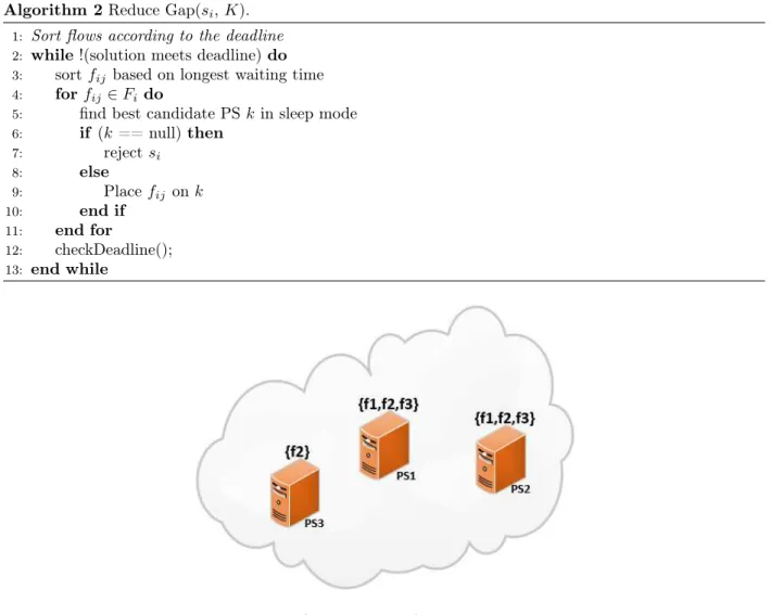
Algorithm 2Reduce Gap(si, K).
1: Sort flows according to the deadline
2: while !(solution meets deadline)do
3: sortfij based on longest waiting time
4: forfij ∈Fi do
5: find best candidate PS kin sleep mode
6: if (k== null)then 7: rejectsi 8: else 9: Placefij onk 10: end if 11: end for 12: checkDeadline(); 13: end while
Figure 5: Small Network State Illustration.
3.2.1
Algorithm Explanation
In this section, we explain the functionality of our algorithm (also presented in Algorithm 1), which is given the name ofEnergy Aware Consolidation.
For each functionj of flow si (denoted byfij), the algorithm searches for all the PSs, that are in active
mode, and that can serve this function (i.e., the PS is hosting a VNF of the same type as that of fij). The
PSs found are sorted in an increasing order, based on the availability timeak of this function of the PS (e.g.,
the time at which this VNF becomes available). If no PSs are found, the algorithm selects a PS that is in sleeping mode, provided it is hosting a VNF of this type. A preference is given to the PS capable of hosting more functions; that is, if two PSs in sleep mode, are found to be able to serve a particular function, the one who has the largest number of VNFs hosted on it is picked first. if no PS in sleep mode, that is hosting
a VNF of this type, is found, the flow is rejected. Once the last function of a service is successfully placed and scheduled, the algorithm checks if the deadline is met or not. If it was not, an alternative placement should be made. In order to do so, the algorithm calculates the delay between each pair of functions (i.e., the finishing time offij and the starting time offi(j+1)). Indeed, a delay, if present, is a result of a busy PS. Therefore, a new PS must be found for this function. The algorithm picks the function with the largest delay, finds a new PS, from the pool of PSs in sleep mode and that have the appropriate VNF, and schedules the function on it. Moreover, the functions following that with the largest delay are also replaced and scheduled. The algorithm keeps on re-checking the deadline, until either the deadline is met, or no new server is found for a function that needs to be re-placed. In the former case, the flow is admitted, and rejected in the latter.
3.2.2
Benchmarks
In order to properly evaluate the efficiency of our proposed solution, we compare it two greedy, energy oblivious algorithms for the placement of the service functions.
Minimize Flowtime
Algorithm 3Minimize Flowtime(K, S).
1: forsi∈S do
2: forfij ∈Fi do
3: initialize candidate node setK0=
φ
4: K0 =getCandidateNodes();
5: if (K0 ==null)then
6: Rejectsi
7: else
8: Select the best PSkfrom K0
9: Placefij onk
10: end if
11: end for
12: checkDeadline();
13: if (solution exceeds deadline)then 14: rejectsi
15: end if
16: end for
Algorithm 3 aims at minimizing the makespan of the PSs. In order to do so, for each service si, we try
to place everyfij on the PS whose function has the best availability timeak. We do not distinguish between
Evidently, with this method, the number of flows admitted will be maximized, and the makespan of each PS will be minimized. However, this method will generate a high power consumption, due to the utilization of the biggest number of PSs possible.
Consolidation
Our algorithm is effectively the same as consolidation. The only difference is that our algorithm, when searching for a PS in sleeping mode, gives priority to PSs with the largest number of VNFs placed on them. The regular consolidation method doesn’t perform this step.
Indeed, our algorithm mainly relies on consolidation. However, consolidation alone proves that it can have disastrous results, especially in networks where the servers do not have a large number of VNFs placed on them. In fact, the only difference between our algorithm and the consolidation method, is that, when searching for a PS in a sleeping mode, preference is given to that with the biggest number of VNFs placed on them. This step alone reduces, as can be seen in Section 3.3, both the average number of servers used, and the average power consumption of the network. Indeed, this small, yet important step will allow to take advantage of the PSs with the highest numbers of VNFs placed on them, thus accommodating more service functions on a less number of servers.
3.2.3
Algorithms in Action
In order to better understand how the algorithm and the benchmarks work, we provide, an example of a small network (Figure 5), in which we will use these algorithm to place and schedule a flow. In this example, we assume a number of PSs, each of which has a set of VNFs placed on them, some of which are in active mode, with flows already scheduled on them, and others in sleeping mode.
Consider a network with the following PSs:
• P S1: hosts functionsF1 = <f1, f2, f3>, with availability timesak = <2,4,1>.
• P S2: hosts functionsF2 = <f1, f2, f3>, with availability timesak = <0,5,2>.
Assume a new flows1 with the following characteristics:
• s1: F1 = <f11, f12, f13>,t1j = <1,2,3>,p1j = <1,1,1>,d1 =4.
We begin by explaining how our algorithm works. As explained in Section 3.2.1, we iterate on every function of the flow. We begin by searching for the set of PSs (in active mode) that can service each function, sort them based on their availability times, and place and schedule the function on it. By doing so, we placef11onP S2, and bothf12 andf13onP S1. While this placement is legitimate, one can notice, in Figure 6(a), that the deadline is not met. With this placement, it takes 6 timeslots to fully processs1. This delay is caused by functionf2 ofP S1. In fact,f12 has to wait 3 timeslots, after the finish time off11, before being processed. In order to overcome this problem, we switch P S3 into active mode, and place f12 on it. The new schedule, shown in Figure 6(b), surely meets the deadline, since now the total processing time ofs1 decreased to 3 timeslots, which is less thand1. Note that if the network did not contain another PS able to servicef12, for exampleP S3, the service would have been rejected.
Next, we describe the functionality of theMinimize Flowtimealgorithm (Alg. 3). For each function, the algorithm finds the PS with the corresponding VNF, and that has the best availability time. The algorithm does not care, nor does it give any priority between PSs in active or sleep mode. Figure 6(b) presents the schedule resulted from this algorithm. note that the schedule is the same as that of our algorithm in this example. However, this is not always the case, since our algorithm is a tradeoff between Consolidation, and minimizing the makespan.
Finally, we present the consolidation algorithm. For each function, the algorithm searches for any server in active mode, and that can host the function. Beginning by P S1, the algorithm notices that the PS can host all three functions ofs1. In this scenario, the deadline is not met (Figure 6(c)). Therefore, the flow is directly rejected. Even though there are other PSs that can accommodate the functions ofs1, the algorithm, with its greedy nature tries to find the first PS that can host each function. If at the end, the deadline of the flow is not met, it is directly rejected.
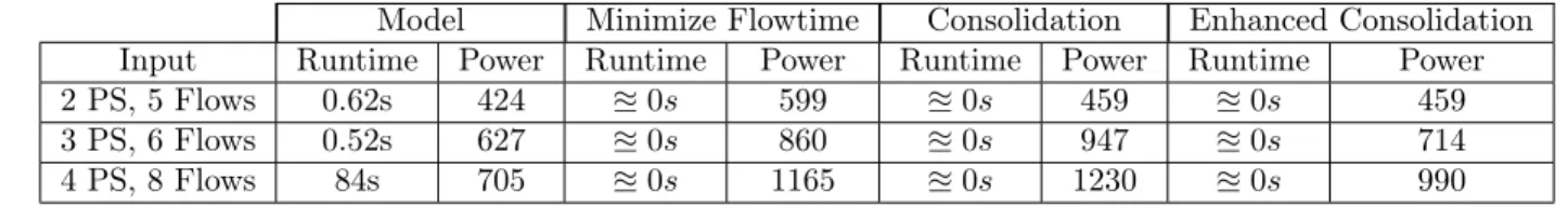
Model Minimize Flowtime Consolidation Enhanced Consolidation Input Runtime Power Runtime Power Runtime Power Runtime Power 2 PS, 5 Flows 0.62s 424 u0s 599 u0s 459 u0s 459
3 PS, 6 Flows 0.52s 627 u0s 860 u0s 947 u0s 714
4 PS, 8 Flows 84s 705 u0s 1165 u0s 1230 u0s 990
Table 2: Comparison Between the Model and the Algorithms
3.3
Numerical Results
3.3.1
Model vs algorithms
Table 2 evaluates the results of the mathematical model, our proposed solution, and the two benchmarks, on small scale networks. The comparison consists of the runtime, and the average power consumption. Clearly, none of the three algorithms provide the optimal solution, that is generated by the mathematical model. However, several important observations can be extracted from the table:
• Minimizing the makespan leads to an excessive power consumption of the network. Indeed, as explained previously, the algorithm tends to use as many resources available as possible, in order to minimize the service time of the flows. the advantage of such algorithm is that it accelerates the servicing of the flows, and thus decreasing the chance of any SLA violation.
• Energy Oblivious Consolidation is not enough. Indeed, the results show that the power consumed by the consolidation is higher than that produced by the algorithm that minimizes the makespan. The only case where regular consolidation saves energy is when all the PSs host all the VNFs. However, in the other case, regular consolidation performs poorly. A logical explanation to these results exists. As explained, consolidation involves using the smallest number of servers needed. this means that even though a smaller number of servers is used, the makespan of each server is increased, and this also increases the power consumption.
• Energy Aware Consolidation is needed. This method also tries to minimize the number of PSs needed. It does so, by consolidating the functions on the smallest number of PSs. However, this method prioritizes the PSs with the largest number of functions on them. This reduces the number of PSs needed even more than the energy oblivious consolidation. Therefore, even though the makespans of
the PSs here are also long, the reduced number of PSs used compensates for these long makespans. The results in Table 2 support these observations. Indeed, the power consumption generated by the energy aware consolidation algorithm is the closest to that of the mathematical model, and it is much less than that generated by both the energy oblivious consolidation and makespan minimization algorithms.
Next, we test our proposed solution on large scale networks:
3.3.2
Compared Algorithms
Simulation Environment
In order to test our proposed solution, we have implemented a discrete event simulator using JAVA. The simulation was ran on a Windows 7 64-bit operating system machine with an 2.67GHz Intel Xeon CPU and 4GB Installed RAM.
The results prove that a framework that places and schedules services with the sole purpose of minimizing the makespan may induce a higher cost on the network operators. In fact, our solution, as will be seen, is very efficient in saving energy. In our simulations, we analyse the power consumption, admission rate, average server utilization, and runtime. We test these metrics by varying the number of services to be admitted, the average number of VNFs on a PS,the network size, and the average deadline of a fixed number of services.
Simulation Parameters
We define a total of 10 different network functions. Each flow may hold between 5 to 10 functions. Each function has a processing time between 1 and 5 timeslots. The deadline of each service is set to be between 25 and 35 units of time, in addition to the total processing times of the service functions. The aforementioned parameters are generated using a uniform distribution. Each point on the graph is the average of 10 runs. Table 3 summarizes the different values considered for each parameter. Similar to [29], we choose the maximum power of a PS to be 250W per timeslot. Therefore, the baseline power, which represents 70% of the PS running at maximum load, has a value 175W per timeslot. Considering the fact that a PS may hold at most 10 functions, we then assume that the energy consumed of each function running at a particular
Parameter Values
Nodes 100
Number of Flows 10-1500
Functions 10
Number of VNFs on a PS 2-9 Functions per service 5-10 Function processing time 1-5
Service deadline 25-35 Baseline power 250 Energy proportion power 7.5 Table 3: Parameters and Values.
timeslot to be 7.5W. Since we are solving the offline problem, we assume that all of the services that need to be placed and scheduled arrive together at the same time.
Performance Metrics
We evaluate our proposed solution (EACons) and compare it with the one that minimizes the makespan
(mintime) and the regular consolidation algorithm (EOCons) based on four performance metrics: The average power consumption, the average server utilization, the admission rate, and the runtime.
• Average Power Consumption: The goal of this paper is to minimize the network’s power con-sumption. Evidently, neither minimizing the makespan, nor minimizing the number of servers used contributes alone in minimizing the power consumption. The power consumption is affected by several factors, namely, the number of PSs turned on, the amount of time each is turned on, the placement and schedule of service functions on PSs, etc. The average power consumption is the total power consumption divided by the total number of admitted flows.
• Average Server Utilization: We evaluate the average number of servers used to admit a certain batch of flows. typically, mintime is expected to be using the largest number of servers. However, this metric serves to test the difference in the number of servers used by EOCons and EACons, since only one of them accounts for the number of VNFs on each PS. The average server utilization is the total number of used server divided by the total number of admitted flows.
• Admission Rate: Maximizing the number of services admitted into the network is an important factor in determining the effectiveness of the solution. It is important to maximize the number of flows
accepted. Moreover, a maximized admission rate reflects the ability of the solution in optimize the network resource consumption. The admission rate is the total number of admitted flows divided by the total number of flows.
• Runtime: Placing and scheduling service flows in a datacenter comprising a large number of PSs, each of which has a different set of VNFs, while optimizing network resources, and respecting the service flows deadlines, is not an easy task to do. However, an efficient framework must be able to cope with completing such a task, for a large number of flows in a matter of seconds.
Simulation Results
We test the algorithms in two different scenarios: varying the number of flows, and varying the average deadline for the network flows. Each of these scenarios will highlight the advantages of our proposed solution. Varying the number of services allows us to monitor the network’s behaviour and performance in managing different loads of services. In fact, varying the load on the network tests the ability of each algorithm to place and schedule the flows, in a way to optimize the server utilization, network power consumption, and admission rate.
Figure (7) depicts the results of the three algorithms while varying the workload. Our proposed solution outperforms the other benchmarks in every aspect except for the runtime. Indeed, mintime handles 1500 flows in less than a second, whileEOCons does it in 1.5 seconds. On the other hand, our solution,EACons
requires around 13 seconds to perform the same task (Figure (7(a))). This extra time is due to the fact thatEACons is not as greedy as the other two algorithms. In fact, not only does it search for the PSs with the best availability, but it also searches for the PSs with the most VNFs on them, in order to optimize the network resources. Moreover, handling 1500 flows in 13 seconds is considered rapid in such a large datacenter and large amount of flows. All three algorithms have the same admission rate Figure (7(b)), proving that all three admit as many flows as possible. The rate begins to drop as the number of flows increases, leaving no place to schedule any other functions on servers and meet the deadlines of the flows. Figures (7(c)) and (7(d)) show the results of the average power consumption and average server utilization respectively. The results highlight the importance of our proposed solution. Indeed, the results of all three algorithms
(a) (b)
(c) (d)
Figure 7: Network Performance in Function of a Variable Workload.
come closer to one another when the network becomes congested. This is essentially logical since when the network is congested, all the network resources are used. However, one can notice the importance of our solution when the network is not congested. Logically,mintime, which aims to minimize the makespan, uses the largest number of servers and consumes energy the most. More importantly, however, is the comparison betweenEACons andEOCons. The former, by prioritizing servers with the largest number of VNFs proved its effectiveness by reducing the number of servers used and the average power consumption in the network. Indeed, consolidation alone may reduce the energy consumption, and definitely reduces the number of servers used, by stacking as many functions on PSs as possible, however, distinguishing the functions on the PSs allowed to greatly reduce the number of PSs used, and therefore, the average power consumption of the network.
To further test our solution, we fix the number of flows to 1500, and vary the minimum deadline of a flow. This allows us to analyze the advantages of our solution on flows with loose or no deadlines, and test its effects on the network.
(a) (b)
(c) (d)
Figure 8: Network Performance in Function of a Variable Deadline.
Figure (8) shows the performance of the network as the deadline of the services changes. As explained above, the acceptance rate is the same for all three algorithms, and the EACons still requires more time to admit the flows. Moreover, the results of the average power consumption and average server utilization shown in Figures (8(c)) and (8(d)) respectively further strengthen the importance of our solution. When the deadline is strict, both the average server utilization and the average power consumption is almost similar for all three algorithms. This is essentially due to the congestion of the network and the unavailability of better placements to schedule the numerous functions on. However, as the deadline becomes more loose, one can notice that the average power consumption remains almost steady and only drops a bit with theEACons, and the average server utilization drops down. On the other hand even though the average server utilization with theEACons also drops, with the increase of the deadline, it is still higher than that ofEOCons. This
3.4
Conclusion
Network Function Virtualization is regarded as a promising technology to overcome the problems imposed by the hardware MiddleBoxes. Despite their numerous advantages, the virtual network functions come with quite a few challenges that need to be addressed, in order to better benefit from them. One important issue is finding the optimal placement and scheduling of the network services on these functions.
In this chapter, we solve this problem, by formulating an ILP model that tries to optimally place and schedule network services on virtual network functions, while also optimizing the total network power con-sumption. Due to the non-scalability of the ILP model, we design an algorithm to solve the problem on large scale networks.