APPLICATION AND DESIGN OF
AIR-TO-AIR VARIABLE REFRIGERANT FLOW SYSTEMS by
PAUL WICOFF
B.S., Kansas State University, 2010
A REPORT
submitted in partial fulfillment of the requirements for the degree
MASTER OF SCIENCE
Department of Architectural Engineering and Construction Science College of Engineering
KANSAS STATE UNIVERSITY Manhattan, Kansas
2010
Approved by: Major Professor Julia Keen
Abstract
This report addresses the operation, use, and design of air-to-air variable refrigerant flow systems, also known as VRF. Relatively new to the United States, these HVAC systems have potential to reduce energy consumption and utility costs in the correct applications. Although useful in many applications, the best building types for VRF are those requiring a large number of zones and with low ventilation air requirements. The report explains design and system selection considerations and accordingly presents two flowcharts to help designers implement this system. To show how the system compares to traditional technologies in terms of efficiency and cost, the report presents results from several studies comparing VRF to other systems. In addition, an energy modeling study is conducted to clarify the effect of climate on the system; this study established air-to-air VRF as having highest energy consumption in dry, southern climates, based on energy use and operating costs. With this report, HVAC designers can learn when air-to-air VRF is an acceptable method for providing heating and cooling in a building.
iii
Table of Contents
List of Figures ... v
List of Tables ... vii
Acknowledgements ... viii
Chapter 1 - Introduction ... 1
1.1 What is Variable Refrigerant Flow ... 1
1.2 Reasons for Slow Adoption in the United States ... 4
1.3 Advantages ... 6
1.4 Disadvantages ... 9
1.5 Useful VRF Applications ... 11
Chapter 2 - Operation... 13
2.1 Major Equipment and Components ... 15
2.1.1 Outdoor Components ... 15
2.1.2 Indoor Components ... 18
Chapter 3 - Design ... 24
3.1 Heat Pump or Heat Recovery System ... 24
3.2 Sustainability ... 25
3.3 Code Compliance ... 28
3.4 Latent Heat ... 30
3.5 Building Load Profile and Unit Selection ... 31
3.6 Piping ... 32
3.7 Power and Maintenance Accessibility ... 33
3.8 Controls ... 33
3.9 Specifications ... 34
3.10 System Completion and Commissioning ... 35
Chapter 4 - System Selection ... 37
4.1 Zoning ... 37
4.2 Refrigerant ... 38
iv
4.4 Ventilation ... 39
4.5 Costs ... 42
4.6 Building Space Allocation ... 43
Chapter 5 - Comparison of VRF to Conventional Systems ... 45
5.1 VRF vs. Chiller/Boiler Hydronic Systems ... 45
5.2 VRF vs. Conventional DX Systems ... 46
5.3 VRF vs. Heat Pump Systems ... 48
5.4 VRF vs. VAV Systems ... 49
Chapter 6 - Climate Study... 51
Chapter 7 - Recommendations and Conclusion ... 58
Bibliography ... 61
Appendix A - Design Flowchart ... 64
Appendix B - Latent Heat ... 66
Appendix C - Example Specification ... 69
Appendix D - System Selection Flowchart ... 87
Appendix E - Climate Study Building Floorplans ... 89
Appendix F - Climate Study TRACE 700 Values ... 93
v
List of Figures
Figure 1.1 VRF Systems ... 2
Figure 1.2 Self-balancing Heat Recovery System. ... 4
Figure 2.1 The Refrigeration Cycle. ... 14
Figure 2.2 The Heat Pump Cycle. ... 15
Figure 2.3 Outdoor Units. ... 16
Figure 2.4 Indoor Units. ... 19
Figure 2.5 Three-pipe Heat Recovery System. ... 22
Figure 2.6 BC Controller. ... 22
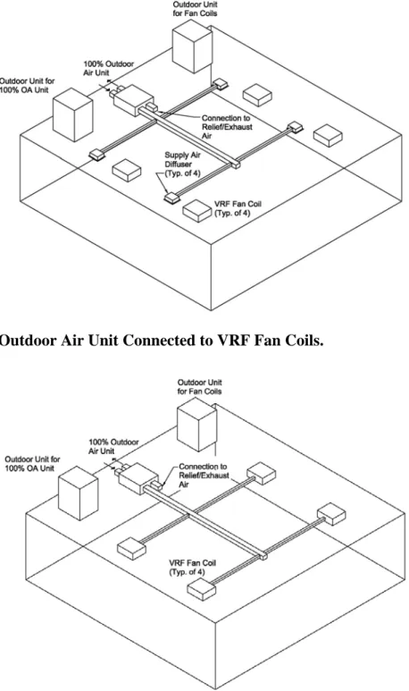
Figure 4.1 100% Outdoor Air Unit Independent of VRF Fan Coils ... 41
Figure 4.2 100% Outdoor Air Unit Connected to VRF Fan Coils. ... 41
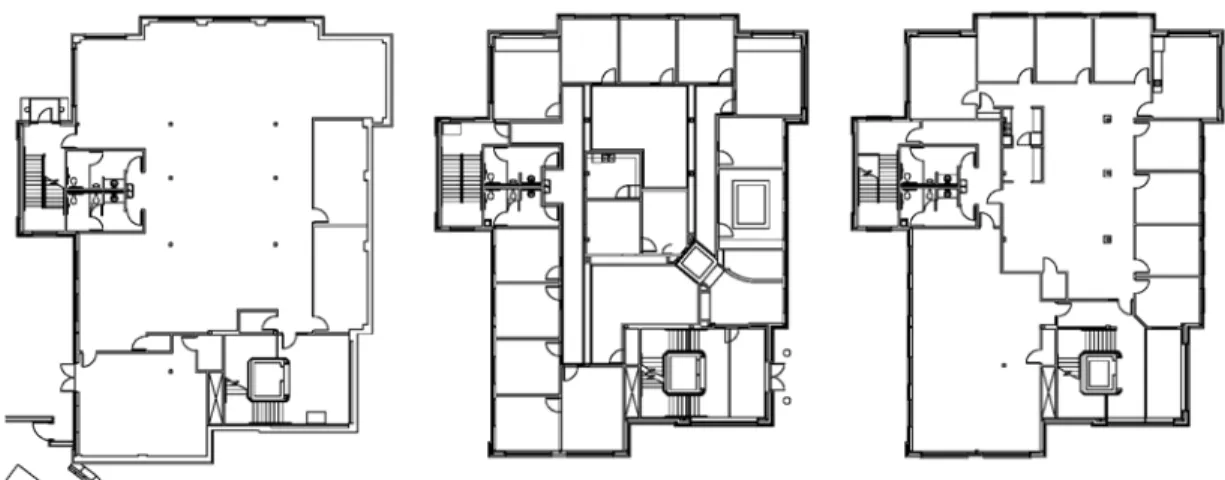
Figure 6.1 Building Floorplan... 52
Figure 6.2 Building Peak Cooling and Heating Loads. ... 54
Figure 6.3 Total Yearly Building Electric Consumption. ... 54
Figure 6.4 Total Cooling Equipment Electric Consumption. ... 55
Figure 6.5 Total Heating Equipment Electric Consumption. ... 55
Figure 6.6 Total Yearly Operating Costs. ... 56
Figure A.1 Design Flowchart ... 65
Figure B.1 The Cooling Curve... 67
Figure B.2 The Supercooling and Reheat Process. ... 68
Figure D.1 System Selection Flowchart. ... 88
Figure E.1 First Floor Plan ... 91
Figure E.2 Second Floor Plan ... 92
Figure F.1 Floor Construction... 95
Figure F.2 Partition Construction ... 96
Figure F.3 Roof Construction ... 97
Figure F.4 Wall Construction and Glass Type ... 98
Figure F.5 Lights, Miscellaneous Loads, People, and Ventilation ... 99
vi
Figure F.7 Miscellaneous Load Schedule ... 101
Figure F.8 Lighting Schedule ... 102
Figure F.9 Availability Schedule ... 103
Figure F.10 Lighting and Utility Rate Schedule ... 104
Figure F.11 Cooling and Heating Equipment ... 105
Figure F.12 Heat Rejection ... 106
Figure F.13 Plant Values... 107
Figure F.14 System Checksums ... 109
Figure F.15 Monthly Utility Costs ... 110
Figure F.16 Energy Consumption Summary ... 111
Figure F.17 Equipment Energy Consumption ... 112
vii
List of Tables
Table 1.1 VRF Advantages and Disadvantages. ... 11
Table 3.1 VRF Minimum Efficiency Requirements. ... 27
Table 6.1 Climates and Corresponding Locations ... 51
Table 6.2 Design Temperatures for Studied Locations ... 52
viii
Acknowledgements
The author wishes to express sincere appreciation to Dr. Keen for her assistance in the preparation of this manuscript. In addition, the author would like to thank Professors Hasler and Kramer for their comments and insight on ideas in this paper.
1
Chapter 1 - Introduction
As of 2008, the commercial building sector was responsible for 19% of energy consumption in the United States; of which 32% is dedicated to space heating, space cooling, and ventilation loads (Center for Sustainable Systems, 2009). As reducing energy consumption becomes a higher priority, heating, ventilation, and air conditioning (HVAC) designers in the United States’ building and construction industry are specifying systems in which sustainable design lowers energy use in commercial buildings. Variable refrigerant flow systems (VRF) are HVAC systems that have great potential to reduce energy consumption when applied correctly. This research addresses the most common type of this technology, air-to-air VRF. Water-to-air VRF systems exist, but little published research exists on them, making accurate discussion about the use and efficiencies beyond the scope of this report. However, research has shown that these systems can expand the use of VRF into areas where air-to-air systems are generally less efficient than water-to-air systems, particularly dry, southern climates. This report defines air-to-air VRF, describes how it works, details how to properly design and select the system, compares the system to more traditional systems, and investigates the effect of climate on the overall performance and operating costs of the system.
1.1 What is Variable Refrigerant Flow
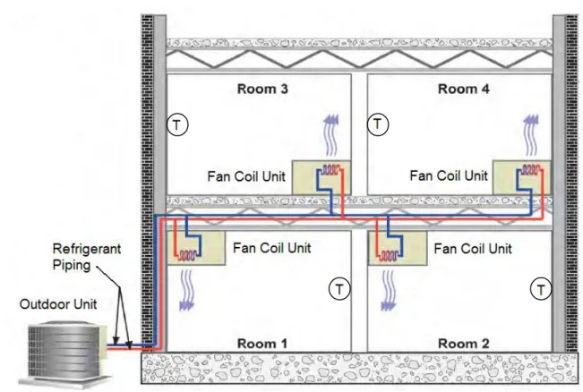
The term VRF stems from ability of the system to modulate the amount of refrigerant flowing to each indoor unit, called a fan coil unit. The system runs constantly at loads between 10% and 100%, but cycles on and off only at loads below 10% (Nye, 2002). To provide heating and cooling, this HVAC system utilizes refrigerant piped via one set of pipes from a single outdoor condensing unit, referred to simply as an outdoor unit, to terminal fan coil units indoors; these will be referred to as fan coil units throughout this report and should not to be confused with traditional fan coil units commonly used in hydronic systems. Instead of using hot water for heating and chilled water for cooling, these fan coils utilize refrigerant delivered via a single pipe for either heating or cooling; in some climates, electric backup heat is required in addition to the basic VRF system. Regardless, each VRF fan coil unit receives only the volume of refrigerant needed to condition the space so that each unit meets the specific needs of each zone
when individual temperature controls are provided (Goetzler, 2007). One outdoor unit can accommodate up to 60 indoor units and loads up to 25 tons, rendering the system useful in almost any size structure and extremely versatile in the commercial building industry (Amarnath & Blatt, 2008). Figure 1.1 illustrates how these fan coil units are connected to the outdoor unit.
Figure 1.1 VRF Systems. (Modified with permission by Ammi Amarnath and the Electric
Power Research Institute)
This system can be utilized in a wide variety of commercial buildings, including offices, hotels, historical renovations, additions, hospitals, and schools (Roth, Westphalen, Dickmann, Hamilton, & Goetzler, 2002). In the past, such buildings have been conditioned primarily by conventional HVAC systems, including hydronic systems, variable air volume systems, conventional direct expansion split systems, and heat pump systems. However, designed and implemented properly, VRF can match the zoning and flexibility of these systems much more efficiently and comfortably, making VRF a viable option for an HVAC system.
Two types of VRF systems exist: heat pump systems and heat recovery systems. Heat pump systems require a refrigerant liquid line and suction line be connected to the outdoor unit. This type of system provides either all heating or all cooling because it cannot perform both
3
functions simultaneously, limiting this type of systems implementaion (Amarnath & Blatt, 2008). With heat pump VRF systems, buildings that have zones requiring cooling during the heating season will need two separate heat pump VRF systems; one system can serve the zones requiring year-round cooling, and one can serve the remainder of the zones. However, the non-year-round cooling zones will still have variable cooling and heating loads; if some of these zones require cooling while others require heating, the heat pump system can only provide conditioning to match the load requirements of the majority of the zones.
In contrast, heat recovery VRF systems allow simultaneous heating and cooling
operation. These systems have a secondary advantage in that heat is transferred between zones, maximizing system efficiency. Specifically, refrigerant is circulated between zones in either a two- or three-pipe system configuration (Goetzler, 2007). This can greatly reduce the use of the central outdoor unit when the system is heating and cooling simultaneously in different zones and can transfer heat between the zones. Moreover, self-balancing takes place when the
demands for heating and cooling are equal. In three pipe systems, heating units absorb heat from a central refrigerant line while cooling units reject heat to the central line; meanwhile, two pipe systems utilize a device called a branch controller, or BC controller, to transfer heat between zones. Figure 1.2 illustrates how the heating and cooling loads of different fan coil units can yield a net load of 0 BTUh in either two- or three-pipe systems. In this case, the compressor will only operate to circulate refrigerant throughout the piping loop, and when one load is greater than the other, the compressor must make up the difference in demand (Inman, 2007).
Figure 1.2 Self-balancing Heat Recovery System.
1.2 Reasons for Slow Adoption in the United States
VRF has been designed and installed for several decades in Europe and Japan but has seen limited use in the United States. This is not because of any particular problem with the system, but rather a result of several external factors: designer and client unfamiliarity with the system, the different construction process, a lack of regulations encouraging the use of
alternative systems, limited publicity and advertising, and historically low energy costs. The first external affecting the use of VRF is unfamiliarity with the system. Most designers in the United States are familiar with ducted direct expansion (DX) systems and hydronic systems and are confident these systems will function properly in specified
applications. However, lack of knowledge and experience with VRF has influenced designers to be hesitant to recommend installations. Because VRF are strongly marketed for applications commonly served by traditional hydronic systems, designers typically have not chosen VRF systems over these more familiar, conventional systems. In addition, building owners are not
5
likely to request a VRF system to be considered for their properties because they have not heard of the system and its energy savings potential (Goetzler, 2007). Unfamiliarity by designers and building owners is echoed in the construction sector as well.
The slightly different construction process required by VRF is the second factor hampering the use of this system. Installing a VRF system is different from installing other technologies, and each VRF manufacturer has specific requirements with which a contractor must be familiar. For example, one manufacturer may specify a maximum refrigerant piping length of 100 feet while another might have an allowable length of 175 feet; exceeding these lengths can reduce the ability of the system to meet the space load. Another difference arises as a result of manufacturers developing their own VRF system layouts; pipe fittings and unit configurations can differ among manufacturers. These variations can make the competitive bidding process complicated, since finding comparable products for substitution is difficult. Because of variable construction requirements, contractors first must invest time to learn the specific requirements of a manufacturer’s system. Also, most contractors have limited
installation experience with VRF and as a result and will charge more for installation, making owners less likely to invest in the system (Goetzler, 2007).
The third factor contributing to the slow adoption of VRF technology is lack of
regulations that would encourage its use. In Japan, where the technology was developed, system use was increased by Japanese regulations. To alleviate strain on the electric grid, Japanese authorities prohibit electric chiller installations in large commercial buildings, which consume a significant amount of electricity for cooling (Ryan, 2008). Because of this legislation, designers were forced to seek other options, and as a result, VRF was installed in more projects. If similar regulations were implemented in the United States, American designers would likewise have to explore alternative sources of heating and cooling. As the focus on reducing energy
consumption in the United States intensifies and as the popularity of the energy rating system LEED grows, VRF will likely be considered more often, particularly in areas prone to brownouts and blackouts.
Limited publicity and advertising has also contributed to VRF systems not being widely used in the United States. VRF was first introduced by companies based in Asia, which had limited representation in United States markets until recently. This rendered advertising and exposure to the product minimal (Goetzler, 2007). Clearly, designers willing to explore
6
alternative technologies will lead the industry toward VRF systems. Also, as these foreign companies and their products become more widely-known by U.S. designers and building owners, the demand for their VRF systems should increase.
Finally, historically low energy costs have significantly slowed adoption of VRF into the United States. When VRF was introduced into the country during the 1980s, the United States had very low energy costs (Amarnath & Blath, 2008), and low operating expenses associated with running an HVAC system was not the priority it is today. Fortunately, recent increases in energy rates and a push to minimize energy dependence have made systems that are energy efficient and low-cost to run and maintain more desirable. This change in mindset will likely allow VRF to gain in popularity.
1.3 Advantages
VRF systems have several characteristics that make the technology promising: potential for submetering, efficiency, comfort, design benefits, ease of installation. Additionally, some aspects of maintenance also favor this type of system. Each of these benefits will be discussed further in the following paragraphs.
One attractive aspect of the system is the potential for submetering within the system. The cost of energy consumed by the outdoor unit must still be divided between tenants; but each VRF indoor fan coil unit could be submetered, allowing building owners to bill occupants individually for their electric consumption (Goetzler, 2007). This cannot be done with systems utilizing a central unit serving different tenant spaces; for example, a central air-handling unit with variable-air-volume reheat could serve multiple spaces but could not be submetered. From a building owner standpoint, submetering allows more accurate billing capability for buildings leased to multiple occupants. In addition, this could encourage patrons in multi-tenant buildings to reduce their energy use since they would have to pay directly for consumption. This factor, in addition to the high efficiency of the system, can serve to curtail energy waste.
Next, for several reasons, VRF technology is highly efficient. The Department of Energy has listed it as one of the top 15 technologies with potential for a significant impact on energy savings (Dickens, 2003). In particular, VRF has higher part load and seasonal energy
efficiencies, because the outdoor unit compressor motor speed can be modulated. In buildings with zones requiring simultaneous cooling and heating demand, heat recovery VRF systems can
7
transfer heat from one space to another, further reducing energy consumption. In addition, VRF eradicates or minimizes air leakage and temperature changes through ductwork since little or no duct work is necessary depending on the fan coil unit configuration selected. Non-ducted units completely eliminate all duct losses; this is significant because duct losses can range from 10% to 20% of the airflow in a ducted system (Goetzler, 2007). Also, the VRF system can be used in the United States Green Building Council, or USGBC, LEED building certification system. Although LEED is a rating system often requested by owners and not necessarily a direct measure of energy efficiency, HVAC designs that meet the requirements of this certification are likely candidates to reduce energy consumption.
Third, comfort levels are very good with VRF technology. The indoor fan coil units can each have individual control, allowing for zoning and individual selection of temperatures for each zone (Amarnath, 2008). Also, VRF systems reduce temperature drift in the space by keeping the compressor and indoor unit fans running constantly during most part load situations instead of cycling on and off, resulting in temperature drifts as low as ±1⁰F. For a disabled fan coil unit in a space with multiple units, that room can likely be comfortably occupied while repairs are being made; meanwhile, load normally handled by the disabled fan coil can be handled by the operational fan coil units. Moreover, if failure occurs in the sole unit conditioning a room, only that room will be negatively affected. Finally, if one of the two compressors in the outdoor unit fails, the other will be available to provide some cooling until the other is repaired (Goetzler, 2007).
In addition to the high degree of thermal comfort, the system also has good acoustic properties, with noise as low as 24 dBA for fan coil units and 56 dBA for outdoor units (Siddens, 2007). However, this is the low end for the system; most indoor units operate around 30 dBA and most outdoor units operate around 60-65 dBA. These ranges are competitive with those of other systems; most diffusers are selected with a maximum noise criterion of 30 dBA, and outdoor equipment can range from as low as 50 to over 75 dBA. The noise level of VRF, combined with the constant operation of the indoor fan, helps create an environment where occupants will not be disturbed by mechanical equipment. Noise can be further minimized by locating ducted fan coils outside the occupied space such as above the corridor or in an adjacent storage space.
8
Finally, indoor air quality is increased by minimizing ductwork compared to split systems and even some hydronic fan coil layouts; many indoor units supply air directly to the space. Thus, mold, fungi, and bacteria have fewer places to colonize within the VRF system (Nye, 2002). This can provide significant advantages for people with chronic health issues such as allergies and asthma. All of the factors combine to maximize occupant comfort.
Implementation of a VRF system can offer general design benefits. Because the system requires minimal airflow through ductwork, duct sizes are minimized. In turn, this could reduce the height of each floor of a building or minimize the coordination needed to avoid potential conflicts between the structure and other equipment located in the plenum. With each floor requiring less height, a structure can conceivably hold more floors, or the total building height can be reduced, resulting in construction cost savings and less volume of space to heat and cool. Furthermore, the fan coil units of a VRF system do not need to be installed in a separate
mechanical room (Goetzler, 2007). This creates more useable floor area for an owner (Cendon, 2009). VRF systems are also expandable; unfinished spaces can be fitted later with fan coil units without significant changes to the system, and space use changes can be accommodated with minimal rework to the system (Goetzler, 2007).
Installation of the VRF system can be straightforward once contractors have familiarized themselves with the installation of the specified VRF equipment. Because the system is all electric, no gas connections are needed (Amarnath, 2008). These systems require limited installation of ductwork for ventilation air and for any ducted fan coil units. Furthermore, the system components are all lightweight and relatively small, meaning lifting equipment is not necessary for moving the components into their final locations.
Finally, maintenance can be an advantage for VRF because the units are small and relatively lightweight. Should an indoor unit fail, it can be removed and replaced without major impact to other parts of the building interior; interior walls do not need to be removed, for example. If units are ducted from unoccupied spaces, maintenance is possible without
interrupting building occupants; however, such units should be installed above lay-in ceilings or above an access panel in hard ceilings. Naturally, direct-to-space units are inherently accessible because of their locations within the space. Additionally, some studies indicate that VRF systems have lower overall maintenance costs than hydronic systems in similar applications (Goetzler, 2007); however, these studies could be comparing new VRF systems to old hydronic systems.
9
1.4 Disadvantages
Although the VRF system has many significant advantages, the disadvantages must also be considered to determine if the technology is appropriate for a specific application. Potential obstacles include refrigerant charge, all-electric heating operation, initial cost, and outdoor air limitations. Additionally, some view maintenance for VRF as a drawback. These potential inadequacies can inhibit the use of this system in certain types of buildings.
The large amount of refrigerant required is perhaps the biggest concern related about VRF. Many designers are hesitant to install systems that route such large amounts of refrigerant within the occupied space. If a leak occurs, the entire system refrigerant charge can escape into the space where the leak is located. A VRF system can contain a significant amount of
refrigerant; such high volumes can quickly compromise occupant health. While this does illustrate the need to develop safer refrigerants, VRF can still be safely installed according to ASHRAE 15 - Safety Standard for Refrigeration Systems. As discussed further in Chapter 6 Section 3, designers can achieve compliance by routing refrigerant piping to avoid small rooms, installing mechanical ventilation in rooms with potential for unsafe levels of refrigerant or a refrigerant level monitoring system, utilizing ducted units, and making architectural changes to increase room volumes.
Another drawback to VRF is its all electric heating operation. In northern climates, gas heating is a more cost-effective means to condition than electric resistance (Goetzler, 2007). This is because natural gas is a less expensive utility than electricity in these regions.
Nonetheless, VRF can save on electricity costs and consumption in northern climates when used to replace older, inefficient equipment. In a study by Minnesota Power, a VRF system installed in a building located in Minnesota is projected to reduce the electrical demand of the facility by up to 98,483 KWh per year; the facility had been previously conditioned by a steam boiler, several chillers, split systems, and window mounted units (Variable refrigerant flow zoning research profile, 2009). Such significant savings will not be possible with all buildings; however, the system should be considered to determine if the operating costs are competitive with those of gas-heating based systems. In climates where gas heating predominates, a life cycle cost analysis should be performed to determine if a payback exists. Any disadvantage could be offset because the all-electric technology of the system allows on-site generated energy from photovoltaics, wind, or other means to power the system, further reducing energy costs.
10
The electric operation of the system eliminates any need for a flue for proper gas combustion; also, some utility companies offer rate discounts when the building operates solely on electricity.
The initial cost of the VRF system can be a hindrance to selecting the system for a building. In new construction, VRF system installed costs can be anywhere from 5-20% higher than for conventional systems (Roth, et. al., 2002). This cost difference will likely decrease as contractors become more familiar with the product since they charge higher rates to install a system with which they are not familiar. Also, VRF may be more difficult to justify from a cost standpoint when renovating an existing HVAC system. For example, to replace a traditional hydronic fan coil system in an existing application, all terminal units and piping would require replacement (Goetzler, 2007), but if those components of this system were in good condition, the cost of replacing them would result in unnecessary expense. For such reasons, VRF is much more likely to be installed in new construction.
Next, VRF systems have limited capacity to heat or cool ventilation air (Afify, 2008). This drawback can be addressed by installing a designated outdoor air system, or DOAS
(Goetzler, 2007). Because this may reduce the energy efficiency of the system, a designer must carefully consider whether a DOAS is really a viable option. Because of this limitation, VRF may not be useful in high ventilation applications.
Maintenance for VRF systems has two main drawbacks, including shorter equipment life than some conventional system components and multiple pieces of mechanical equipment. The first, short equipment life span, requires that VRF outdoor units be replaced more often than chillers and boilers in hydronic HVAC systems, which can last up to 30 years (Goetzler, 2007). DX systems are inherently short lived, lasting 10-15 years (Roth, et. al., 2002). However, the cost of replacing a large chiller or boiler may be so high that this drawback is negated; also, access for unit replacement is better for VRF systems. Because filters must be replaced at a room level, and maintenance must be performed on each indoor VRF fan coil unit, variable air volume (VAV) and central air-handling unit systems do have an advantage as far as ease of maintenance is concerned. Although these are noteworthy drawbacks, any HVAC system will have maintenance issues that could be equally costly or problematic. Table 1.1 provides a simplified view of VRF advantages and disadvantages.
11
Table 1.1 VRF Advantages and Disadvantages.
VRF Advantages & Disadvantages
ADVANTAGES DISADVANTAGES Submetering potential High refrigerant charge High efficiency All‐electric technology Good comfort levels Low ventilation air capacity Minimal ductwork High initial cost Easily expandable Equipment life‐span Ease of installation Maintenance at each fan coil Equipment easily replaced Accessibility of fan coils Maintenance costs
1.5 Useful VRF Applications
VRF is useful for a variety of building occupancy types, particularly those with multiple zones. The flexibility and potential for low plenum space required by the system make it a viable choice for additions and historical renovations. Since it is best suited for applications with lower ventilation requirements, VRF is most practical in offices, hotels, and condominiums. Although hospitals and schools require large amounts of outdoor air, the system can still be used if the ventilation air is handled by a separate system (Goetzler, 2007). In fact, VRF provides an excellent method to prevent the mixing of air between zones, becoming a good candidate in spaces where this is a major concern, for instance in healthcare design; however, care must be taken to avoid routing refrigerant piping over patient rooms as Chapter 3.3 discusses (Cendon, 2009). Also, the designer must consider if the owner is going to be occupying the space; building owners who plan to sell or rent out the space may not be interested in the high up-front cost of the system.
VRF should not be considered in applications that are single zone or only have a few zones. For example “big box retail” applications or large warehouses would be best served by traditional DX rooftop units (Goetzler, 2007). The large open space and few zones associated with this type of building make the expense of VRF unjustifiable. Heat recovery systems are particularly useless in this application because no opportunity for self balancing exists.
12
VRF systems are better suited to some climates than others, especially climates with modest heating loads (Roth, et. al., 2002). In extremely cold climates, the heating capacity of the system is reduced, creating a need for electric resistance heating. Next, limitations on wet and dry bulb temperatures can cause trouble in hot humid climates by exceeding the capacity of the fan coils (Afify, 2008). Specifically, per the anaylsis performed in Chapter 6, areas with high cooling design temperatures and low wet bulb temperatures are less favorable for VRF
application than other systems; in short, the system will use more energy than in other climates. These problems can be mitigated with energy recovery ventilators; however, energy use can still increase for VRF in such climates as the analysis in Chapter 6 demonstrates. the energy use of VRF in such climates. If guidance is needed as to what areas of the country are prone to these climatic conditions, Appendix B of ASHARE 90.1 can be referenced.
13
Chapter 2 - Operation
The VRF system consists of several components combined to heat or cool a conditioned space. For every system, at least one outdoor unit containing compressors, fans, condensers, and several valves must serve multiple indoor fan coil units; in some climates, electric heating coils must also be installed. The fan coil units contain a fan, a heat exchanger, and an expansion valve. Refrigerant piping connects the outdoor unit to the fan coil units, allowing refrigerant to transfer heat between units for space conditioning. With this system, heat can be transferred from indoors to outdoors or outdoors to indoors, similarly to how air-to-air heat pumps work. Because of the heat recovery capability, heat can also be transferred from one space to another as further explained in Section 2.1.2, Indoor Components.
The basic refrigeration cycle cools the space, and the heat pump cycle (the reverse refrigeration cycle), is used for heats it. In any system using refrigerant, the compression and expansion of the refrigerant is the basis of space conditioning; refrigerant must be allowed to expand to cool or must be compressed to heat, all while indoor and outdoor devices in the system serve a critical role in either cycle.
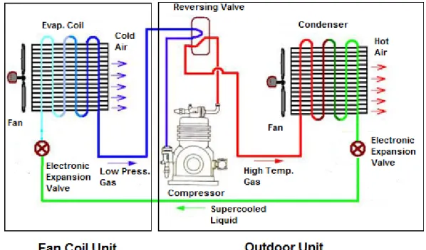
As illustrated in Figure 2.1, the VRF refrigeration cycle process begins with the compressor located in the outdoor unit converting low pressure refrigerant vapor into a high temperature refrigerant gas and delivering it at the vapor saturation point to the condenser in the outdoor unit. The condenser converts this refrigerant gas into liquid refrigerant by rejecting heat to the surrounding atmosphere with the aid of a fan; an electronic expansion valve allows the liquid refrigerant to expand, causing the refrigerant to reach a super cooled stage. The super cooled liquid is delivered from the outdoor unit to each indoor fan coil unit, where it passes through an evaporator coil and absorbs heat from the airstream. The refrigerant then becomes a low pressure gas and returns to the compressor in its initial low-pressure, gaseous state.
Notably, this graphic shows only a single fan, condenser, and compressor in the outdoor unit for the sake of clarity; a unit actually contains two of these in parallel, as Section 2.1.1 explains.
Figure 2.1 The Refrigeration Cycle. (Modified with permission by the Singapore National
Environment Agency).
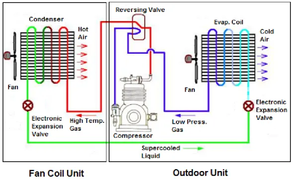
In heating mode, the refrigeration cycle is reversed; the flow of refrigerant is reversed by a reversing valve within the outdoor unit, causing the outdoor condenser to become an
evaporator and the evaporator within the fan coil unit to become a condenser. The refrigerant is delivered to each fan coil as hot gas; the coil in the unit acts as the condenser by rejecting heat to the conditioned space and causing the refrigerant phase to change from gas to liquid. The liquid refrigerant passes through the outdoor condensing unit, which acts as an evaporator by absorbing heat from the atmosphere. The refrigerant is then sent through the compressor and converted to a hot, high pressure gas. Figure 2.2 illustrates this process. As discussed in Section 2.1.1, Outdoor Components shows, the outdoor unit has two fans, two condensers, and two compressors, but these have not been shown for the sake of clarity.
Figure 2.2 The Heat Pump Cycle. (Modified with permission from the Singapore National
Environment Agency).
2.1 Major Equipment and Components
The air-to-air variable refrigerant flow system needs several different components. Also, fan coil units must be selected for every thermal zone being conditioned, while an outdoor unit must be selected to handle the load of the multiple indoor fan coil units (Amarnath & Blatt, 2008). Thus, connected by one set of refrigerant pipes, both the outdoor unit and fan coil units are composed of components essential for proper heating and cooling.
15
2.1.1 Outdoor Components
An air-to-air VRF system consists of an outdoor unit serving up to 60 indoor fan coil units via one set of refrigerant pipes (Amarnath & Blatt, 2008). For heat pump systems, each outdoor unit can have a heating and cooling capacity anywhere between 12,000 and 300,000 BTUh. Heat recovery systems have a larger minimum capacity; 72,000 BTUh is currently the smallest unit available (Variable Refrigerant Flow, n.d.). These outdoor units contain two
compressors, two condensers, two fans, and an accumulator (Xia, Winandy, Georges, & Lebrun, 2004). The outdoor unit is comparable to a traditional air cooled condensing unit, or ACCU, used in typical direct expansion cooling systems such as split systems. However, the big difference is
that the outdoor VRF unit can act as an air-to-air heat pump by drawing heat from the atmosphere during heating mode because of the integral reversing valve.
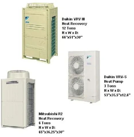
The actual appearance and size of an outdoor unit varies depending on the manufacturer, the expected load, and whether it is serving a heat pump or a heat recovery VRF system. Figure 2.3 below provides an example of this variation. The manufacturer, model, type of system, unit capacity, and unit dimensions are given for each unit.
Figure 2.3 Outdoor Units. (Images printed courtesy of Daikin AC and Mitsubishi Electric).
Two hermetic scroll compressors are contained in the outdoor unit to compress the refrigerant, turning it into a high temperature gas; they both operate using the processes
illustrated in Figures 2.1 and 2.2. One is variable speed and one is constant speed; each is sized for half the total capacity of the outdoor unit. The variable speed compressor is used most of the time and its motor modulates anywhere from the full capacity of the compressor to a minimum speed of 10% (Nye, 2002). If the load becomes higher than what the variable speed compressor can handle alone, the constant speed compressor turns on, and the frequency of the variable speed compressor is reduced to handle any excess load above 50%. Once loads are reduced to
17
below 50%, the constant speed shuts off, and the variable speed compressor operates exclusively. If the load requires the variable speed compressor to operate below its minimum frequency, the compressor will shut off and cycle on if needed to avoid the inefficiency related to hot-gas bypass (R. Froebe, personal communication, September 16, 2010).
The variable speed compressor is the key to energy savings with the VRF system in that it utilizes an electronically commutated motor (ECM), also known as a brushless DC motor, and a variable speed inverter drive to gain an edge in efficiency over conventional compressors. The ECM, fitted with a magnetic rotor to prevent loss of efficiency at low speeds, boosts the overall efficiency of the condenser dramatically; some estimate that the motors are up to 30% more efficient than traditional induction motors (Amarnath, 2008). Meanwhile, the variable speed inverter drive is responsible for controlling the speed of the compressor ECM by allowing the motor to operate at a high speed initially to reach the conditioned space temperature set points; once these set points are reached, the variable speed drive will reduce the rpm of the ECM, keeping it running continuously to maintain the desired temperatures in served zones (Amarnath, 2008). These two technologies combine to create a variable speed compressor motor system that is generally 82-90% efficient; however, below 30% loading, this compressor system efficiency starts to drop dramatically (Amarnath, 2008). This is why the motor turns on and off completely below a predefined minimum capacity; occupant comfort will not be compromised because the system will still operate despite not running constantly.
Most manufacturers use two parallel condensers in the outdoor unit to handle the load of the building, one for each compressor, and each condenser is coupled with one variable speed fan. These condensers are really heat exchangers capable of serving also as evaporators. They serve as condensers when rejecting heat to the air during cooling mode and as evaporators when absorbing heat from the atmosphere during heating mode, depending on the direction of
refrigerant flow. The two variable speed fans facilitate this heat transfer by forcing air to pass over each condenser; having a variable speed motor on these fans allows power consumption to be reduced at part load (Xia et. al., 2004).
An accumulator is needed in the outdoor unit because compressors can only handle vapor refrigerant; in fact, this device is needed for any DX system. Not shown in Figures 2.1 and 2.2 , the accumulator is located between the compressor and the reversing valve and captures liquid refrigerant and oil, preventing it from entering and damaging the compressor. The accumulator
18
contains a metering device that converts the liquid refrigerant into a vapor and sends this refrigerant and oil to the compressor (The Role of the Suction Line Accumulator, 2001).
The outdoor unit needs several valves as well, including a reversing valve and expansion valves. A reversing valve is needed to control the direction of refrigerant flow for heating or cooling mode; this is controlled by the HVAC control system. The controls system will switch the direction of the valve depending on the load borne by the fan coil units. In heat pump systems, a majority of zones calling for cooling will send a signal to the valve, causing it to facilitate the refrigerant cycle; the opposite is true when a majority of zones call for heating. In heat pump systems, the controls system will reverse the direction of the valve depending on the total net load on the building. Also, the system has two expansion valves (Xia et. al., 2004); these are located downstream of each condenser to allow refrigerant to expand and reach a super-cooled temperature after passing through either condenser.
2.1.2 Indoor Components
After the refrigerant has passed through the outdoor unit, it goes into the building to provide conditioning. With the VRF system, several components must be located indoors including fan coil units, expansion valves, piping, and controls. These are all components essential for the efficient, local control associated with this system.
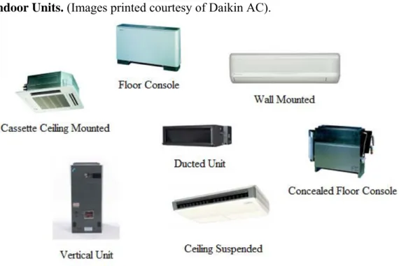
VRF fan coil units provide air distribution in each space being conditioned. Each unit can be paired with a thermostat to create a zone, or multiple units may be grouped together with one thermostat either to create fewer zones or to handle zones with loads exceeding the capacity of a single fan coil unit. Each unit is capable of providing anywhere from 5,000 to 120,000 BTUh of cooling or heating (Variable Refrigerant Flow, n.d.). The units can be in the space to directly supply conditioned air or can be ducted to provide air to rooms where a visible unit is not desired. Examples of both ducted and non-ducted units are in Figure 2.4. Direct-to-space units can be cassette ceiling mounted, ceiling suspended, wall mounted, floor consoles, or concealed floor consoles; however, with noise levels around 30 dBA, these could be excessively noisy in some applications. Designers should reference manufacturer data for exact noise levels of direct-to-space units. Ducted units, which would reduce the amount of mechanical noise in a space, can be horizontal or vertical units.
Figure 2.4 Indoor Units. (Images printed courtesy of Daikin AC).
The styles of units seen in Figure 2.4 are not the only styles available from manufacturers. Many variations in appearance exist; one manufacturer even offers a wall mounted unit that is disguised as artwork. In addition to different aesthetic options, many manufacturers offer both low profile units for shallow plenum depth applications and standard size units for situations with more generous plenum space. Capacities vary based on the style of unit selected; therefore, designers should reference manufacturer performance data to select fan coils.
Direct-to-space units are generally at or below the finished ceiling height; therefore, many manufacturers specify integral condensate drain pumps to avoid any drainage problems. Condensate will occur during cooling mode when the temperature of the coil is lower than the dew point of the air, with the amount dependent on the latent load treated by the coil.
Accordingly, condensate piping must be designed and sized for the specific conditions of the building.
Electronic expansion valves are essential to the VRF system to modulate delivery of the correct volume of refrigerant to each unit (Xia et. al., 2004). The valve is usually installed by the manufacturer inside each indoor fan coil unit. However, some manufacturers locate the valves outdoors in a distribution box (Obella, 2009). An outdoor distribution box means the system requires more piping and a separate piping circuit for each indoor unit; this is not a common
20
configuration. In both cooling and heating mode, the expansion valves modulate to deliver refrigerant at a manufacturer-specified temperature and pressure; to maximize efficiency. If an indoor unit is turned off, its expansion valve will remain slightly open to prevent refrigerant from becoming trapped in front of the unit. Because the expansion valves are located at each fan coil, balancing problems such as pressure drop and short circuiting are eliminated. As with any DX system, VRF must use oil return, the process by which oil used for internal lubrication of the compressor is returned to the compressor after escaping into refrigerant lines. During this process, the expansion valves open, and the compressor runs at high speeds set by the manufacturer; therefore, any oil resting in refrigerant lines is swept back to the compressor (Variable Refrigerant Flow, n.d.).
Refrigerant piping connects the outdoor unit and each indoor fan coil unit in the VRF system. Because the expansion valves will balance the system properly, the quantity of pipe can be minimized because the system can be laid out as a direct return system. As with any
refrigerant piping, VRF piping must be insulated to prevent condensation from forming on the pipe surface and to minimize heat gain or loss from the refrigerant as it travels between the fan coil unit and the outdoor unit. Although heat pump and heat recovery piping systems differ slightly, one set of pipes connects the outdoor unit to the indoor units in both cases; however, the number of pipes in each set of pipes can vary.
For heat pump systems, the refrigerant can be delivered to the indoor units as either a cool liquid for cooling or a hot gas for heating, limiting the system to providing either heating or cooling. Alternatively, heat recovery VRF outdoor units, which allow for simultaneous heating and cooling, deliver refrigerant to the indoor units as a mixture of gas and liquid. The
manufacturer determines the means by which this multi-phase mixture is delivered to the indoor units.
In a heat pump VRF system, the outdoor unit is connected to the indoor units by two pipes, a liquid line and a suction line. The liquid line acts as the refrigerant supply line. When selected with a small diameter, the pressure drop in this line will increase; conversely, pressure drop will decrease with a larger diameter. Because of the expansion valves located at each fan coil unit, pressure drop from the piping diameter off this line is not a major concern. Meanwhile, the second pipe, or the suction pipe, serves as the return piping from the fan coils to the outdoor unit. Here, pressure drop can have significant impact, as excessive drop can cause a 20% loss of
21
cooling capacity in the compressor; to maintain a high coefficient of performance (COP) for the compressor, manufacturers must also try to keep the pressure constant. In addition, the diameter of the suction piping must be sized correctly or oil return will be compromised (Variable
Refrigerant Flow, n.d.). Correct sizing can be accomplished with manufacturer design programs, which will provide pipe sizes after the system layout has been input.
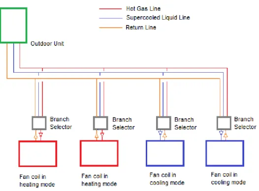
For heat recovery systems, most manufacturers offer a three pipe system consisting of a liquid line, a suction line, and a discharge line; however, a two pipe system is available from one manufacturer. In three pipe systems, all three pipes are connected to the outdoor unit. The discharge line supplies hot gas, and the liquid line supplies liquid refrigerant to a device often referred to as a branch selector; a suction line is also connected to this device. A solenoid valve on each line and a heat exchanger are located at the branch selector. Each fan coil unit has a specified branch selector; the heat exchangers within the selector allow heat to be transferred from the return line to the hot gas line. When a zone requires cooling, the solenoid valves on the liquid line and the suction line open. When heating is required, the hot gas and suction line valves open (Goetzler, 2007). The refrigerant flows through the suction line back to the
outdoor unit, which works to make up any difference between the net heating and cooling loads; when the net load is zero, the compressor will run at the minimum speed to keep refrigerant moving through the system. Figure 2.5 illustrates how this system is laid out. Although this three pipe system may seem inefficient on first inspection, this is what allows heating and cooling loads to cancel out, reducing the energy consumption of the outdoor unit.
Figure 2.5 Three-pipe Heat Recovery System.
For the two pipe heat recovery system, gas and liquid are mixed and travel over the same supply line; a branch controller, or BC controller, separates this gas-liquid mixture and sends the necessary refrigerant phase to each fan coil unit (Air Conditioning & Heat Pump Institute, 2010). A suction line and a liquid/gas line from the outdoor unit connect to one side of the controller. Multiple refrigerant supply and return connections are located on another face of the device; one of each is needed for every fan coil unit, requiring significant branch piping. Figure 2.6
illustrates a BC controller.
Figure 2.6 BC Controller. (Used with permission by Mitsubishi Electric).
Thus, refrigerant is delivered via the piping to each fan coil unit. Older VRF systems utilize R-22, which provides little to no savings in efficiency over traditional chillers (Goetzler, 2007). However, with the push for more environmentally friendly refrigerants, R-410a has become the more prevalent in VRF systems, with a 5% higher refrigeration efficiency than R-22
23
(Inman, 2007). Because of this higher refrigerant efficiency and the higher part-load efficiencies of the new systems that use R-410a, research by one VRF manufacturer has found that R-410a VRF systems can gain 30-40% energy savings over chiller systems (Goetzler, 2007); however, the refrigerant utilized by the chillers in this study is unknown. These savings may be inflated if the chillers in these studies utilized R-22. Additionally, these values may be skewed if the chillers and pumps in the comparison were single speed.
Controls must be provided for each zone served by a fan coil unit; these controls are then connected to a central control system. To create maximum levels of individual control and realize the full advantages of the VRF system, a thermostat is paired with each individual fan coil. If, however, the zone is large enough that multiple fan coils are needed to condition the space, it is possible to link one thermostat with multiple units. While no maximum number of fan coils can serve a single zone, each zone must have a minimum of one fan coil unit
(Technology Spotlight: Heating and Cooling with VRF Systems, 2008). The temperature set point for each unit is monitored and set using direct digital control (DDC) technology; however, manual overrides could be provided at the space level to allow the occupants to modify the temperature as well. DDC allows for centralized control of these potentially complex, sprawling systems and permits for remote control of the system via the Internet (Variable Refrigerant Flow, n.d.). This function is useful for building owners and managers who want to be able to easily monitor and control temperatures in their buildings. BACnet or other traditional control systems can be paired with VRF, but some manufacturers have developed control systems to handle their specific systems. Using a manufacturer’s HVAC control system ensures that the specific
requirements are addressed for the complex VRF system, so if one is offered, it should be selected. If temperature setbacks are wanted when the space is unoccupied, the DDC software can be programmed with setback schedule. If this is not desired, a programmable thermostat linked to the control system can set temperature schedules in a space (Afify, 2008). Because the DDC control system could monitor occupancy allowing energy use to be minimized better than programmable thermostats could, this would be the preferred method for controlling the space temperature. In addition, with a ventilation air unit, the same DDC control system used for the fan coil units would need to control the ventilation system and any fans or dampers.
24
Chapter 3 - Design
Once a designer has determined that VRF is the best choice for a building, the design phase can begin; Appendix D contains a design flowchart to assist a designer at this stage. Ideally, a designer should select a VRF manufacturer before carrying out the design process; this could be based on quality of manufacturer regional support, company reputation, and designer familiarity with manufacturer products. Basing a design on a specific product is necessary because each manufacturer will have different system requirements. In the design process, the designer must make several design decisions based on the following questions addressed in this chapter:
• Will a heat pump or heat recovery system be used? • What sustainable goals apply to the project? • How will code compliance be achieved? • Can the building latent load be met? • How will piping be sized and routed?
• How will the building equipment be located for access? • What controls will be provided for the system?
• What must be provided in the specifications, especially if a competitive bid is needed? • What final steps should be taken to ensure correct system operation?
These considerations are laid out in the flowchart illustrated in Appendix A. A designer can reference this flowchart for the order of the design steps. Each step references a section of this chapter that explains further the considerations the designer must make. Although this reference can provide a designer with some insight into VRF, reading the paper in its entirety will make a designer most familiar with any potential limitations, advantages, or design requirements this system has.
3.1 Heat Pump or Heat Recovery System
When designing an air-to-air VRF system, designers should consider the number of zones needing cooling or heating at one time. When a building can be conditioned using all cooling or
25
all heating, heat pump VRF systems are best; however, this situation is not often encountered in the commercial sector because most buildings have some sort of data or server room that
requires year round cooling. However, heat pump systems require less piping, less equipment, and lower initial costs than heat recovery systems, which may make it a desirable option regardless of this need for year-round cooling. When some zones require year-round cooling, inline duct fans or exhaust fans could be installed in these areas to remove warm air and pull in conditioned air from surrounding space; of course, this applies only to rooms that do not contain highly sensitive electronic equipment. Alternatively, two separate heat pump systems could be installed; one could serve the year-round cooling areas, and one could provide conditioning for the other zones.
If the building being designed is expected to have some zones in cooling and some in heating simultaneously, the designer may want to consider a heat recovery VRF system. This type of system has higher initial costs than a heat pump system because VRF outdoor units are more expensive than the heating or cooling only units (Afify, 2008), in part because of the need for branch selectors and a third pipe. Even though this initial cost may be higher, heat recovery systems do use less energy than heat pump systems; therefore, long term costs will be lower. When deciding which option of VRF to choose, designers should remember that heat recovery VRF outdoor units are not available below 6 tons (Variable Refrigerant Flow, n.d.). Thus, buildings with block loads smaller than this may be better served by heat pump systems.
3.2 Sustainability
With more focus on sustainable design, a designer may need to create a VRF system that complies with one of several sustainable design guidelines, energy codes, or building rating systems. Meeting such requirements is possible with VRF. Because of the capability of the motors to operate at reduced speed, the VRF system reduces energy consumption when handling part loads. Heat recovery systems further reduce energy consumption by transferring heat from spaces needing cooling to spaces needing heating.
For sustainable design, a designer could reference one of the following codes: ASHRAE 90.1 - Energy Standard for Building Except Low-Rise Residential Buildings; ASHRAE 189.1 – Standard for the Design of High-Performance Green Buildings Except Low-Rise Residential Buildings; California Title 24; or local energy codes to achieve a rating with LEED or Energy
26
Star. ASHRAE 90.1 is quite commonly used, so learning its requirements for VRF is important for a designer who expects to use this technology. Although ASHRAE 189.1 has not been adopted as code yet, it is being considered by some jurisdictions and can provide a valuable sustainable design reference for any designer. California Title 24 requirements must be considered by designers who plan on working on VRF projects in that state. Finally, with the increasing popularity of LEED with building owners, likely, a designer will need to consider this certification.
In the summer of 2010, ASHRAE adopted the new AHRI Standard 1230 to provide minimum efficiency ratings for VRF under ASHRAE Standard 90.1-2007. These values are the minimum ratings for VRF equipment and are not difficult to attain. Indeed, the minimum efficiencies required are very low for what is achievable with VRF because ASHRAE did not want to provide an overly challenging requirement for such a new system (Ivanovich, 2010). Nonetheless, these efficiencies are higher than those required for other DX systems in ASHRAE 90.1-2007. The AHRI 1230 efficiency values required for air-to-air VRF systems per ASHRAE Standard 90.1, obtained from Mitsubishi Electric, are in Table 3.1. Currently, this is the only part of ASHRAE 90.1 that specifically addresses VRF systems; however, the requirements listed in Chapter 6 - Heating, Ventilating, and Air Conditioning, of ASHRAE 90.1 still apply to the system.
27
Table 3.1 VRF Minimum Efficiency Requirements.
Electrically Operated Variable Refrigerant Flow Air‐to‐Air Minimum Efficiency Requirements
Size Category Heating Section Type Sub‐Category or
Rating Condition Minimum Efficiency
<65,000 BTUh All VRF Multi‐split System 13.0 SEER
≥65,000 BTUh and <135,000 BTUh Electric Resistance (or none) VRF Multi‐split System 11.0 EER 12.3 IEER 12.9 IEER (as of 7/1/2012) ≥65,000 BTUh and <135,000 BTUh Electric Resistance (or none) VRF Multi‐split System with Heat Recovery 10.8 EER 12.1 IEER 12.7 IEER (as of 7/1/2012) ≥135,000 BTUh and <240,000 BTUh Electric Resistance (or none) VRF Multi‐split System 10.6 EER 11.8 IEER 12.3 IEER (as of 7/1/2012) ≥135,000 BTUh and <240,000 BTUh Electric Resistance (or none) VRF Multi‐split System with Heat Recovery 10.4 EER 11.6 IEER 12.1 IEER (as of 7/1/2012) ≥240,000 BTUh Electric Resistance (or none) VRF Multi‐split System 9.5 EER 10.6 IEER 11.0 IEER (as of 7/1/2012) ≥240,000 BTUh Electric Resistance (or none) VRF Multi‐split System with Heat Recovery 9.3 EER 10.4 IEER 10.8 IEER (as of 7/1/2012) ASHRAE 189.1 puts several constraints on a VRF system. VRF is not specifically addressed but applicable items that influence the system design are addressed. For example, Section 6.3.2.3 - HVAC Systems and Equipment, requires condensate to be recovered for reuse from units with capacities greater than 65,000 BTUh, and VRF fan coil units have capacities as high as 120,000 BTUh. If designing to 189.1, an appropriate recovery system will need to be designed for fan coil units that have capacities within this 65,000-120,000 BTUh range.
28
for any system applying zone level cooling. To address the reuse aspect of this section, condensate piping can be routed to grey water retention vessels for recycling. Section 9.3.3 - Refrigerants, states that CFC-based refrigerants cannot be used; R-410a is not a CFC-based refrigerant, so specifying a VRF system using this refrigerant would meet the requirements of the standard. Because R-22 is a CFC-based refrigerant, VRF systems using this refrigerant cannot be specified to comply with ASHRAE 189.1. This does not pose a significant problem since most new VRF systems utilize R-410a in lieu of R-22.
The 2008 California Title 24 does not specifically address VRF. However, meeting the code requirements is possible by modeling the energy usage of the building according to the performance compliance path described in Chapter 9 - Performance Approach of this standard. Having lower consumption than the base energy usage defined by Title 24 can result in
compliance; this should not be overly difficult to attain. Currently, EnergyPro and TRACE 700 are the only modeling programs that have options for modeling VRF and could be used to achieve compliance for Title 24 using the performance approach (Ivanovich, 2010).
VRF can be designed successfully to meet minimum requirements of the most popular building rating system, LEED 3.0 (administered by USGBC), and even generate up to 22 points toward the certification in the following categories:
• Energy and Atmosphere (EA) Credit 1, Optimize Energy Performance • EA Credit 3, Enhanced Commissioning
• EA Credit 4, Enhanced Refrigerant Management
• Indoor Environmental Quality (IEQ) Credit 6.2, Controllability of Systems-Thermal Comfort
• IEQ Credit 7.1, Thermal Comfort-Design • IEQ Credit 7.2, Thermal Comfort-Verification.
Each of these credits has aspects directly related to the design of a VRF system. Earning these credits is not guaranteed, however; a designer must be careful to comply with the
requirements of each credit throughout system layout and design.
3.3 Code Compliance
As with any system, an extremely important step in the design of a VRF system is to consider its compliance with building health and safety codes, such as the International
29
Mechanical Code. Meeting these code requirements is relatively easy with this system; however, concerns can occur with the requirements of several standards referenced by the code, including ASHRAE 15 - Safety Standard for Refrigeration Systems, ASHRAE 34 - Designation and Safety Classification of Refrigerants, and ASHRAE 62.1 - Ventilation for Acceptable Indoor Quality. Although keeping refrigerant concentrations low and providing outdoor air may seem
challenging, VRF systems installed in Europe have met requirements of similar European codes (Goetzler, 2007).
Designers can assure compliance with ASHRAE 15 - 2004 and ASHRAE 34 - 2004 simply by following the guidelines set forth in these standards. Since these standards deal with the concentration of leaked refrigerant in occupied space, it is important for designers to realize that the entire refrigerant charge can escape through one leak because one set of pipes serves all units. The following discussion shows how a VRF system utilizing R-410a determines
compliance with these standards.
The first step in reaching compliance is to determine the maximum concentration allowed in a space. Table 1 in ASHRAE 15 lists common refrigerant blends and their respective
allowable concentrations; a designer should be aware that for institutional occupancies, buildings in which occupants cannot leave because of health or security reasons, the values in this table are reduced by 50% per Section 7.2.1. These concentration values are all based on ASHRAE 34. In the case of a discrepancy between the two standards, ASHRAE 34 governs. Because R-410a has not been included on Table 1, ASHRAE 34 must be consulted for maximum allowable
concentrations of this refrigerant. Per ASHRAE 34, Table 2, R-410a has a Refrigerant Concentration Limit (RCL) of 25 lb/1000 ft3.
The second step is to determine the minimum allowable room volume for the VRF system being considered. The refrigerant charge of the system, often given in pounds, must be divided by the RCL. The resulting volume will be the minimum volume any room containing refrigerant piping or equipment can have without additional of mechanical ventilation. This example assumes a refrigerant charge of 40 lbs; a designer could find this value for a VRF system in the manufacturer’s outdoor unit data. Dividing 40 lbs by 25 lb/Mcf renders a minimum room volume of 1600 ft3.
Once the minimum allowable room volume has been determined, the designer must calculate volumes for all rooms that piping is routed within to ensure that none fall below this
30
value, referring to ASHRAE 15, section 7.3. This section provides guidelines explaining what determines the boundaries of a completely enclosed room. If any completely enclosed room volumes are less than the minimum allowable volume, mechanical ventilation must be installed per Section 7.3.1. For example, a room with a volume of 1500 ft3 would not meet the minimum room volume requirement of 1600 ft3; thus, mechanical ventilation would be required.
Whenever the maximum allowable concentration of refrigerant of either code is exceeded for a space, mechanical ventilation can remove the refrigerant in the case of a leak. To minimize the need for mechanical ventilation, the piping could be strategically routed only through spaces exceeding the minimum volume; for instance, a ducted VRF unit could be located outside the space to prevent refrigerant piping from being routed in these small rooms. Also, the room volume could be increased to dilute the refrigerant by raising the ceiling, providing an undercut door to another space, or connecting the space to another room via a transfer grill (Variable Refrigerant Flow, n.d.). However, this solution may not always be possible for several reasons. First, architectural or construction limitations may exist preventing the implementation of this method. Second, additional expense can be incurred by undercutting a door or by supplying a transfer boot; in the case of a fire wall penetration, this cost would increase even more due to the need for a fire/smoke damper. Finally, creating openings between rooms can create an open path for noise; this could be a major concern with adjacent counseling or patient rooms.
ASHRAE 62.1 compliance can also be achieved using VRF. Some manufacturers will offer outdoor air kits to at least precondition ventilation air being sent via ducts to the fan coils. However, if the external static pressure capabilities of the outdoor units are exceeded, a separate DOAS can condition ventilation air (Afify, 2008). With a separate system, ductwork will need to be routed throughout the building to each space requiring ventilation air as described in Section 4.4. Designers should always check manufacturer data to ensure that an outdoor air ductwork connection can be made to the fan coil unit. If not, the outdoor air ductwork could be connected to return air ductwork on ducted units or supplied directly to the space via a diffuser.
3.4 Latent Heat
As Section 4.4 mentions, VRF, like many cooling systems, has limited capacity to neutralize latent heat, which can be introduced to a system externally via ventilation air or generated internally by people, equipment, or infiltration. When selecting VRF equipment, the
31
designer must remember that latent heat removal only occurs in the cooling process when enough sensible cooling has occurred to allow latent cooling. This process is illustrated by the psychrometric chart in Appendix B. In most VRF applications, this is not a problem. If latent loads are found too high according to psychrometric analysis, the problem can be solved by selecting a ducted unit and setting it to cool the air low enough to remove moisture from the air stream. Because this air will be too cold to deliver to the space, an electric heating coil can be placed in the supply ductwork to reheat the air to an acceptable delivery temperature. This solution, illustrated on a psychrometric chart in Appendix B, should only be applied when absolutely necessary since the process is inefficient and may lead to problems with static pressure drop for the ducted fan coil unit. To reduce the negative effect reheating has on efficiency, a sequence could be programmed into the building controls system to reduce the amount of cooling done by the DX coil when relative humidity is low enough. As Section 4.4 states, energy recovery ventilators can quite effectively remove latent heat from ventilation air, although they may be initially more expensive.
3.5 Building Load Profile and Unit Selection
Selecting equipment that can handle the load is essential to proper building conditioning and system performance. Ventilation loads, envelope loads, and internal loads must be
determined in order to size indoor and outdoor equipment. Designers should first select the indoor fan coils followed by selecting an outdoor unit to accommodate those indoor units.
Each individual fan coil is sized based on the peak load, or worst case load, of the zone being served. Over-sizing the units must be avoided to avoid problems with humidity control, to permit the electronic expansion valve to modulate, and to avoid problems with pressure drop and fan coils receiving the wrong amount of refrigerant (Variable Refrigerant Flow, n.d.). For this reason, the engineers should calculate accurate loads for the space, including both sensible and latent loads.
The total capacity of all the fan coils can be greater than, equal to, or less than the capacity of the outdoor unit, which must be able to handle 70-130% of the total fan coil cooling or heating capacity. Manufacturers have various limitations on sizing outdoor units any higher than this range; among manufacturers, the most a unit can be over-sized is 200% of the total indoor unit capacity. Because outdoor units only need to handle the block load, or overall peak